EP0052983B1 - Wire transfer mechanism - Google Patents
Wire transfer mechanism Download PDFInfo
- Publication number
- EP0052983B1 EP0052983B1 EP81305370A EP81305370A EP0052983B1 EP 0052983 B1 EP0052983 B1 EP 0052983B1 EP 81305370 A EP81305370 A EP 81305370A EP 81305370 A EP81305370 A EP 81305370A EP 0052983 B1 EP0052983 B1 EP 0052983B1
- Authority
- EP
- European Patent Office
- Prior art keywords
- wire
- transfer
- arm
- gripper means
- transfer arm
- Prior art date
- Legal status (The legal status is an assumption and is not a legal conclusion. Google has not performed a legal analysis and makes no representation as to the accuracy of the status listed.)
- Expired
Links
Images


Classifications
-
- H—ELECTRICITY
- H01—ELECTRIC ELEMENTS
- H01R—ELECTRICALLY-CONDUCTIVE CONNECTIONS; STRUCTURAL ASSOCIATIONS OF A PLURALITY OF MUTUALLY-INSULATED ELECTRICAL CONNECTING ELEMENTS; COUPLING DEVICES; CURRENT COLLECTORS
- H01R43/00—Apparatus or processes specially adapted for manufacturing, assembling, maintaining, or repairing of line connectors or current collectors or for joining electric conductors
- H01R43/28—Apparatus or processes specially adapted for manufacturing, assembling, maintaining, or repairing of line connectors or current collectors or for joining electric conductors for wire processing before connecting to contact members, not provided for in groups H01R43/02 - H01R43/26
Landscapes
- Engineering & Computer Science (AREA)
- Manufacturing & Machinery (AREA)
- Manufacturing Of Electrical Connectors (AREA)
- Forwarding And Storing Of Filamentary Material (AREA)
- Specific Conveyance Elements (AREA)
Description
- The present invention relates to a wire transfer mechanism for transporting a length of wire conductor from a feed location to a terminating location and then depositing the length of wire at a collection location, said mechanism comprising a base positionable relative to wire feed assemblies and wire terminating assemblies; a transfer arm movable back and forth between a pick-up position and a termination position; means for moving said transfer arm back and forth at selected intervals coinciding with the operation of a crimping machine and a wire feed machine; releasable gripper means on the transfer arm for gripping a length of wire; and actuator means for releasing said releasable gripper means. Such a mechanism, in accordance with the prior art portion of
claim 1, is known from GB-A-2030898. - When wire leads are processed in a typical apparatus of the type which includes systems for cutting, stripping and/or crimping wire leads, there is a tendency for the wire to bend when it is being transferred from one working location to another by a wire transfer mechanism. It is therefore usual for the apparatus to include a device for straightening the wire as the bending of the wire leads during processing is very undesirable. However, the provision of a wire straightening device in a system for processing electrical wire leads is also undesirable as the efficiency of the overall system is decreased while its cost is increased. United States Patent No. 707 756 illustrates a wire positioner for a terminal attaching machine and is an example of the kind of attempt taught by the prior art in order to avoid the use of a wire straightening device.
- It is an object of the present invention to overcome some basic disadvantages of the prior art wire transferring systems, and to provide a wire transfer mechanism that is adapted to be operated in conjunction with a wire cutting apparatus, a stripping machine and a crimping press in a manner which minimises the possibility of bending the length of wire which is being processed by the system.
- In accordance with the invention, the transfer arm is pivoted proximate one end thereof to the base, and the gripper means is located proximate the other end of the transfer arm, and the actuator means operates to release the gripper means while the transfer arm is moving pivotally from the termination position to the pick-up position at a finite velocity and for decelerating the transfer arm, whereby the momentum of a wire gripped in the gripper means will carry it away from the transfer arm in a direction normal to the axis of the wire.
- In the drawings:
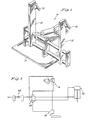
- Figure 1 is a perspective view of a preferred embodiment of an automatic wire transfer mechanism in accordance with the present invention,
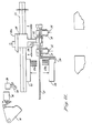
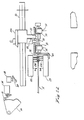
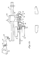
- Figure 2a to 2h are schematic top plan views of parts of a wire lead making system showing the wire transfer mechanism of Figure 1 and illustrating various operational positions, and
- Figure 3 shows a pneumatic system for operating the wire transfer mechanism.
- Referring now to the drawings, and in particular to Figure 1 thereof, a preferred embodiment of automatic wire transfer mechanism in accordance with the present invention is shown at 10. As will be described below, the
mechanism 10 may be used to link a conventional wire cutting and stripping machine to a crimping press to thereby provide a complete electrical wire lead making unit. When incorporated in such a system, the wire transfer mechanism in accordance with the present invention can transfer a measured, cut and stripped wire to the crimping area of a press for the subsequent application of a strip fed terminal to the wire. Once terminated at one end thereof, the wire leads are then delivered to a stacking tray. - The
mechanism 10 includes a base portion 11, and transferarms 12 pivoted at one end thereof to the base portion and, at a position spaced from the pivot axis, articulated to a double-acting pneumatic piston and cylinder unit 41 (Figure 3) for swinging the arms back and forth between several positions. A respective gripper means, preferably in the form of areleasable gripper jaw 13, is located at the other end of each of thetransfer arms 12, the set of gripper jaws cooperating to grip a length of wire in a manner which prevents relative motion of the wire in a direction normal to the wire axis, but permits axial motion thereof. During operation, thegripper jaws 13 open while thearms 12 rotate at a predetermined finite velocity so that the forward motion of the jaws carries a completed lead wire out of the jaws, which are then ready for the next cycle of operation. To receive the next length of wire, thejaws 13 are opened by the engagement of a stop mechanism which advances to meet thetransfer arms 13 early in their return stroke and to open the jaws while the return stroke continues, and then retreats with the transfer arms so that the jaws close after the new wire is engaged. All of these steps occur in a continuously repeatable sequence. Although the particular preferred embodiment of the automatic wire transfer mechanism illustrated in the drawings has twotransfer arms 12, it is to be understood that it is within the scope of the present invention to employ a single arm or three ormore transfer arms 12 each having releasable gripper means, in the automatic wire transfer mechanism described herein. - Figures 2a to 2h show the mechanical components of a wire lead making unit in which the
transfer mechanism 10 may be incorporated. Awire pulling head 18 is movable back and forth along aguide track 21. Thehead 18 carries a wire pullinghead gripper 22 capable of closing on a continuous length ofwire 17 in order to entrain it with the wire pulling head, and then of opening to release the wire during a return stroke of the head. A cutting andstripping guide 23 hasblades 23a and is associated with anactuator bar 24 for the transfer mechanism. The double-acting piston and cylinder unit 41 used to operate the transfer mechanism is controlled by a five-ported fourway valve 40 supplied with air through a filter, lubricator and regulator unit, as shown in Figure 3. Thevalve 40 has a neutral position in which neither of the lines to the cylinder are pressurised, and from which thevalve 40 may be moved into either of two operating positions in order to supply operating air to one or other of the piston chambers. Thevalve 40 is under the control of a three-way diverter valve 16 and a three-way normally closedvalve 19.Valve 40 occupies its neutral position whenvalve 16 is set as shown andvalve 19 is closed. Thevalve 40 is moved to its first operating position whenvalve 19 is opened to thereby move the piston in one direction, and into its other operating position whenvalve 16 is reset to reverse the application of control air, thereby to move the piston in the other direction. - The
valve 16 has acam follower 15 which engages acam 14 secured to a release linkage onwire pulling head 18 so that the valve is actuated by the release ofwire 17 from thewire pulling head 18. Thevalve 19 engages thewire pulling head 18 by way of acam follower 20 engageable with alateral cam 20a so that the valve is activated by the return of the wire pulling head to the start of the pull cycle. - The
valve 16 controls the downward or forward motion of the transfer arms, i.e. provides for their movement to the crimp position. Thevalve 19 controls the upward or backward motion of thearms 12, i.e. controls their movement to the wire pick-up position. - Figure 2a shows the transfer mechanism in its static position. Valve 16 is set so as to supply control air to the inlet of
valve 19 which is closed becausecam follower 20 is out of contact with thecam 20a. Valve 40 is in its neutral position and the cylinder 41 is isolated from operating air. From this position, thewire pulling head 18 advances in the direction shown by arrow 26 in Figure 2b to cause thewire 17 secured bygrippers 22 to be stripped. Thecam 20a on the pulling head now engages thecam follower 20 which trips and opens thevalve 19, settingvalve 40 in its first operating position to feed operating air to the piston and cylinder unit 41 in order to retract its piston rod and begin moving thetransfer arms 12 in the upward direction shown by arrow 28. Also during the stage of movement in which thewire pulling head 18 advances in the direction of arrow 26, the wire cutting and strippingdie set 23 moves to an open position which in turn moves theactuator bar 24 into the position shown in Figure 2c. Thewire pulling head 18 now moves along itsguide track 21 in the direction ofarrow 29 until the required length ofwire 17 has been pulled into position. Concurrently therewith, thetransfer arms 12 have been swung into the intermediate position as shown, and their movement decelerated by positioning of theactuator bar 24 which causes thegrippers 13 to open and the wire lead terminated in the preceding cycle to be released. The momentum of the previously terminated wire causes it to be carried away from the transfer arms in the direction normal to the wire axis, as can be seen happening in Figure 2c. The ejected wire falls into a suitably positioned collection tray. - As shown in Figure 2d, the
wire pulling head 18 stops at the point where the required length ofwire 17 has been pulled. When the pulling head has stopped moving, the cutting and stripping die 23 withblades 23a closes in the direction of arrows 30 allowing theactuator bar 24 to move in and thetransfer arms 12 to move towards the wire pick-up position. - The cutting and stripping die closes fully which in turn moves the actuator bar in fully, thereby allowing the
gripper jaws 13 to grip the length ofwire 31 such as to prevent movement of thewire 31 normal to its axis but to permit it to move parallel to the axis. Thewire pulling head 18 now moves to the far right position in the direction ofarrow 33 to strip theother end 32 of thewire 31. After reaching its extreme position, the wire pullinghead gripper 22 releases thewire 31 and the wire pulling head starts moving back in the direction of thearrow 36 in Figure 2e. As thewire 31 is released, thequadrant cam 14 is rotated in the direction ofarrow 34. by the linkage which controls thewire pulling head 18 and to which the cam is connected. Thevalve 16 is now tripped and diverts control air from the inlet of thevalve 19 to thevalve 40 to reset the latter and cause operating air to be fed to the other side of the piston of the piston and cylinder unit 41 and bring about downward motion of thetransfer arms 12 in the direction ofarrows 35 in order to carry thewire 31 to the crimp position. The wire pulling head continues to move in the direction ofarrow 36 in Figure 2f to the point where its gripper can again pick up the wire. Thetransfer arms 12 swing completely down to the crimp position, during which movement a microswitch is tripped which starts a cam (not shown) tripping an air valve which actuates a small air cylinder to eject thewire 31 for crimping. Thereafter, and as illustrated in Figure 2g, thewire pulling head 18 stops moving and itsgripper 22 closes on thewire 37. Figure 2h illustrates how the pullinghead gripper 22 closes on the wire. As this occurs, thecam 14 is rotated in the direction ofarrow 38, resettingvalve 16 to divert control air from thevalve 40 back to the inlet of the closedvalve 19. Valve 40 returns to its neutral position and the system returns to the static position illustrated in Figure 2A. The entire operation as described above repeats itself in the sequence as described. The wire cut and stripped during the sequence of operations just described is crimped at the crimping position and during the next movement of the transfer arms towards the pick-up position is ejected as the arms reach the position shown in Figure 2c.
Claims (5)
Applications Claiming Priority (2)
| Application Number | Priority Date | Filing Date | Title |
|---|---|---|---|
| US209247 | 1980-11-21 | ||
| US06/209,247 US4490084A (en) | 1980-11-21 | 1980-11-21 | Wire transfer mechanism |
Publications (3)
| Publication Number | Publication Date |
|---|---|
| EP0052983A2 EP0052983A2 (en) | 1982-06-02 |
| EP0052983A3 EP0052983A3 (en) | 1983-01-19 |
| EP0052983B1 true EP0052983B1 (en) | 1985-09-25 |
Family
ID=22777983
Family Applications (1)
| Application Number | Title | Priority Date | Filing Date |
|---|---|---|---|
| EP81305370A Expired EP0052983B1 (en) | 1980-11-21 | 1981-11-12 | Wire transfer mechanism |
Country Status (9)
| Country | Link |
|---|---|
| US (1) | US4490084A (en) |
| EP (1) | EP0052983B1 (en) |
| JP (1) | JPS57170350A (en) |
| AU (1) | AU552542B2 (en) |
| BR (1) | BR8107519A (en) |
| CA (1) | CA1175215A (en) |
| DE (1) | DE3172451D1 (en) |
| ES (1) | ES8302960A1 (en) |
| MX (1) | MX153574A (en) |
Families Citing this family (5)
| Publication number | Priority date | Publication date | Assignee | Title |
|---|---|---|---|---|
| US6468475B1 (en) * | 1999-03-05 | 2002-10-22 | Perkinelmer Instruments Llc | Autosampler |
| US9484722B2 (en) | 2009-03-23 | 2016-11-01 | Southwire Company, Llc | Pulling head assembly workstation |
| WO2011046998A1 (en) * | 2009-10-14 | 2011-04-21 | Southwire Company | Pulling head assembly workstation |
| US9142942B2 (en) * | 2012-12-07 | 2015-09-22 | Reel Power Licensing Corp. | Method for in situ multiple cable terminations |
| EP3599681A1 (en) * | 2018-07-24 | 2020-01-29 | Komax Holding Ag | Cable processing machine device and method for removing cables from a removal trough of a cable processing machine |
Family Cites Families (12)
| Publication number | Priority date | Publication date | Assignee | Title |
|---|---|---|---|---|
| US3104765A (en) * | 1963-09-24 | Article transfer apparatus | ||
| US1626410A (en) * | 1925-11-13 | 1927-04-26 | Int Cigar Mach Co | Transferring device for cigar machines |
| FR61080E (en) * | 1950-10-26 | 1955-03-23 | Houilleres Du Bassin Du Dauphi | Equipment and devices for material handling |
| US3157911A (en) * | 1961-12-08 | 1964-11-24 | Western Electric Co | Apparatus for removing articles from cavities of molds |
| US3245135A (en) * | 1963-06-14 | 1966-04-12 | Kent Mfg Corp | Automatic wire handling device |
| US3537702A (en) * | 1968-04-16 | 1970-11-03 | Union Special Machine Co | Work handling apparatus for use with sewing machines |
| US3707756A (en) * | 1971-02-12 | 1973-01-02 | Thomas & Betts Corp | Wire positioner for terminal attaching machine |
| US3893358A (en) * | 1974-08-02 | 1975-07-08 | Dixon Automatic Tool | Mechanism for unloading parts from a machine |
| US3913751A (en) * | 1974-12-06 | 1975-10-21 | Robert Friedman | Apparatus for automatically feeding and removing cylindrical bodies to and from a working head |
| US4148161A (en) * | 1977-05-02 | 1979-04-10 | Dentsply Research & Development Corp. | Loading unit for an automatic bur grinding machine |
| GB2030898B (en) * | 1978-07-04 | 1982-06-16 | Burndy Corp | Electrical lead transfer unit |
| JPS5566459A (en) * | 1978-11-09 | 1980-05-19 | Matsushita Electric Ind Co Ltd | Conveyor for wire rod |
-
1980
- 1980-11-21 US US06/209,247 patent/US4490084A/en not_active Expired - Lifetime
-
1981
- 1981-11-12 EP EP81305370A patent/EP0052983B1/en not_active Expired
- 1981-11-12 DE DE8181305370T patent/DE3172451D1/en not_active Expired
- 1981-11-13 CA CA000390089A patent/CA1175215A/en not_active Expired
- 1981-11-17 AU AU77569/81A patent/AU552542B2/en not_active Ceased
- 1981-11-19 MX MX190192A patent/MX153574A/en unknown
- 1981-11-19 BR BR8107519A patent/BR8107519A/en unknown
- 1981-11-20 JP JP56186744A patent/JPS57170350A/en active Granted
- 1981-11-20 ES ES507874A patent/ES8302960A1/en not_active Expired
Also Published As
| Publication number | Publication date |
|---|---|
| BR8107519A (en) | 1982-08-17 |
| MX153574A (en) | 1986-11-24 |
| DE3172451D1 (en) | 1985-10-31 |
| AU7756981A (en) | 1982-05-27 |
| US4490084A (en) | 1984-12-25 |
| ES507874A0 (en) | 1983-01-16 |
| EP0052983A2 (en) | 1982-06-02 |
| JPH0138746B2 (en) | 1989-08-16 |
| JPS57170350A (en) | 1982-10-20 |
| CA1175215A (en) | 1984-10-02 |
| AU552542B2 (en) | 1986-06-05 |
| EP0052983A3 (en) | 1983-01-19 |
| ES8302960A1 (en) | 1983-01-16 |
Similar Documents
| Publication | Publication Date | Title |
|---|---|---|
| US3570100A (en) | Insulation stripping attachment for electrical connector crimping press and connector crimping press having insulation stripping means | |
| US5385434A (en) | Electrical connector delivery system | |
| US6135164A (en) | Apparatus and method for preparing wires in a harness making machine | |
| US4403383A (en) | Electrical lead transfer unit | |
| US4860427A (en) | Wire stripping apparatus and an automatic wiring device which incorporates it | |
| CN109217073B (en) | Automatic equipment for assembling wires and wiring terminals | |
| JPH0272576A (en) | Wire processing device | |
| EP0052983B1 (en) | Wire transfer mechanism | |
| US5797299A (en) | Wire cutting and stripping mechanism | |
| GB2092029A (en) | Apparatus and method for connecting the ends of stator windings to their terminals | |
| US3967356A (en) | Insertion tool operable in accordance with a predetermined program to insert a plurality of conductors in insulation-piercing contacts disposed on opposite sides of an electrical connector | |
| US5713249A (en) | Wire stripper | |
| EP0001891B1 (en) | Apparatus for inserting wires into electrical terminals | |
| EP0356504B1 (en) | Apparatus for inserting terminals on the ends of wires into cavities in an electrical connector | |
| US4703543A (en) | Wire insertion apparatus for insulation displacement terminal | |
| EP0041332A2 (en) | Apparatus for, and a method of, inserting electrical terminals into an electrical connector housing | |
| US3062390A (en) | Wire handling apparatus | |
| JPH0666148B2 (en) | 2-step clamp method for electric wire | |
| JPH07211427A (en) | Electric wire straightener in electric wire processor | |
| US5138909A (en) | Hand-held, pneumatic wire stripping tool | |
| US3115695A (en) | Ladder strip crimper | |
| US6357575B1 (en) | Equipment for the feeding of cable ends to finishing treatment units | |
| US4040167A (en) | Method of and a machine for separating and fitting insulated conductors of multi-conductor ribbon cables to connectors in housings | |
| JPS5854500B2 (en) | wire bonding equipment | |
| JPH06290848A (en) | Terminal supplying mechanism |
Legal Events
| Date | Code | Title | Description |
|---|---|---|---|
| PUAI | Public reference made under article 153(3) epc to a published international application that has entered the european phase |
Free format text: ORIGINAL CODE: 0009012 |
|
| AK | Designated contracting states |
Designated state(s): BE CH DE FR GB IT NL SE |
|
| PUAL | Search report despatched |
Free format text: ORIGINAL CODE: 0009013 |
|
| AK | Designated contracting states |
Designated state(s): BE CH DE FR GB IT LI NL SE |
|
| 17P | Request for examination filed |
Effective date: 19830506 |
|
| ITF | It: translation for a ep patent filed |
Owner name: STUDIO TORTA SOCIETA' SEMPLICE |
|
| GRAA | (expected) grant |
Free format text: ORIGINAL CODE: 0009210 |
|
| AK | Designated contracting states |
Designated state(s): BE CH DE FR GB IT LI NL SE |
|
| REF | Corresponds to: |
Ref document number: 3172451 Country of ref document: DE Date of ref document: 19851031 |
|
| PGFP | Annual fee paid to national office [announced via postgrant information from national office to epo] |
Ref country code: NL Payment date: 19851130 Year of fee payment: 5 |
|
| ET | Fr: translation filed | ||
| PLBE | No opposition filed within time limit |
Free format text: ORIGINAL CODE: 0009261 |
|
| STAA | Information on the status of an ep patent application or granted ep patent |
Free format text: STATUS: NO OPPOSITION FILED WITHIN TIME LIMIT |
|
| 26N | No opposition filed | ||
| PG25 | Lapsed in a contracting state [announced via postgrant information from national office to epo] |
Ref country code: NL Effective date: 19870601 |
|
| NLV4 | Nl: lapsed or anulled due to non-payment of the annual fee | ||
| GBPC | Gb: european patent ceased through non-payment of renewal fee | ||
| PG25 | Lapsed in a contracting state [announced via postgrant information from national office to epo] |
Ref country code: FR Free format text: LAPSE BECAUSE OF NON-PAYMENT OF DUE FEES Effective date: 19870731 |
|
| PG25 | Lapsed in a contracting state [announced via postgrant information from national office to epo] |
Ref country code: DE Effective date: 19870801 |
|
| REG | Reference to a national code |
Ref country code: FR Ref legal event code: ST |
|
| PG25 | Lapsed in a contracting state [announced via postgrant information from national office to epo] |
Ref country code: SE Effective date: 19881113 |
|
| PG25 | Lapsed in a contracting state [announced via postgrant information from national office to epo] |
Ref country code: GB Effective date: 19881118 |
|
| PG25 | Lapsed in a contracting state [announced via postgrant information from national office to epo] |
Ref country code: LI Effective date: 19881130 Ref country code: CH Effective date: 19881130 Ref country code: BE Effective date: 19881130 |
|
| BERE | Be: lapsed |
Owner name: BURNDY CORP. Effective date: 19881130 |
|
| REG | Reference to a national code |
Ref country code: CH Ref legal event code: PL |
|
| EUG | Se: european patent has lapsed |
Ref document number: 81305370.9 Effective date: 19890726 |