EP0052684A1 - Testverfahren für eine Anzeigseinrichtung - Google Patents
Testverfahren für eine Anzeigseinrichtung Download PDFInfo
- Publication number
- EP0052684A1 EP0052684A1 EP80304231A EP80304231A EP0052684A1 EP 0052684 A1 EP0052684 A1 EP 0052684A1 EP 80304231 A EP80304231 A EP 80304231A EP 80304231 A EP80304231 A EP 80304231A EP 0052684 A1 EP0052684 A1 EP 0052684A1
- Authority
- EP
- European Patent Office
- Prior art keywords
- testcase
- data
- displayed
- statement
- statements
- Prior art date
- Legal status (The legal status is an assumption and is not a legal conclusion. Google has not performed a legal analysis and makes no representation as to the accuracy of the status listed.)
- Granted
Links
Images


Classifications
-
- G—PHYSICS
- G09—EDUCATION; CRYPTOGRAPHY; DISPLAY; ADVERTISING; SEALS
- G09G—ARRANGEMENTS OR CIRCUITS FOR CONTROL OF INDICATING DEVICES USING STATIC MEANS TO PRESENT VARIABLE INFORMATION
- G09G3/00—Control arrangements or circuits, of interest only in connection with visual indicators other than cathode-ray tubes
- G09G3/006—Electronic inspection or testing of displays and display drivers, e.g. of LED or LCD displays
-
- G—PHYSICS
- G01—MEASURING; TESTING
- G01R—MEASURING ELECTRIC VARIABLES; MEASURING MAGNETIC VARIABLES
- G01R31/00—Arrangements for testing electric properties; Arrangements for locating electric faults; Arrangements for electrical testing characterised by what is being tested not provided for elsewhere
- G01R31/28—Testing of electronic circuits, e.g. by signal tracer
- G01R31/317—Testing of digital circuits
- G01R31/3181—Functional testing
- G01R31/3183—Generation of test inputs, e.g. test vectors, patterns or sequences
- G01R31/318371—Methodologies therefor, e.g. algorithms, procedures
-
- G—PHYSICS
- G01—MEASURING; TESTING
- G01R—MEASURING ELECTRIC VARIABLES; MEASURING MAGNETIC VARIABLES
- G01R31/00—Arrangements for testing electric properties; Arrangements for locating electric faults; Arrangements for electrical testing characterised by what is being tested not provided for elsewhere
- G01R31/28—Testing of electronic circuits, e.g. by signal tracer
- G01R31/317—Testing of digital circuits
- G01R31/3181—Functional testing
- G01R31/319—Tester hardware, i.e. output processing circuits
- G01R31/31903—Tester hardware, i.e. output processing circuits tester configuration
- G01R31/31912—Tester/user interface
-
- G—PHYSICS
- G06—COMPUTING OR CALCULATING; COUNTING
- G06F—ELECTRIC DIGITAL DATA PROCESSING
- G06F11/00—Error detection; Error correction; Monitoring
- G06F11/07—Responding to the occurrence of a fault, e.g. fault tolerance
- G06F11/08—Error detection or correction by redundancy in data representation, e.g. by using checking codes
-
- G—PHYSICS
- G06—COMPUTING OR CALCULATING; COUNTING
- G06F—ELECTRIC DIGITAL DATA PROCESSING
- G06F11/00—Error detection; Error correction; Monitoring
- G06F11/22—Detection or location of defective computer hardware by testing during standby operation or during idle time, e.g. start-up testing
- G06F11/26—Functional testing
- G06F11/263—Generation of test inputs, e.g. test vectors, patterns or sequences ; with adaptation of the tested hardware for testability with external testers
-
- G—PHYSICS
- G06—COMPUTING OR CALCULATING; COUNTING
- G06F—ELECTRIC DIGITAL DATA PROCESSING
- G06F11/00—Error detection; Error correction; Monitoring
- G06F11/30—Monitoring
- G06F11/32—Monitoring with visual or acoustical indication of the functioning of the machine
Definitions
- This invention relates to a digital data display system capable of displaying both alphanumeric and graphic data.
- the invention finds particular use in a system such as described in European Patent Application No 80103734.2 in which the control signals for graphic and alphanumeric displays are generated at a central processing device and then transmitted to visual display units (v.d.u.'s) which may be at remote locations.
- testcase programs which test particular aspects of the system. To write a testcase program by hand will require two to four weeks and as the number of testcase programs to test a system will be in the order of a thousand it can be seen that to manually produce testcase programs suitable for checking a large scale system requires a very large amount of effort.
- United Kingdom Patent Specifications 1,479,122 and 1,510,240 describe methods of operating a computer to produce testcase programs.
- Specification 1,479,122 describes a method of producing testcase programs in which statements are generated on a weighted random basis and a prediction is made to the value of variables changed during the operation of each statement.
- the programs produced by the method are suitable for testing the data calculating and manipulating aspects of a compiler program.
- Specification 1,510,240 describes a method of producing testcase programs suitable for testing the input- output instruction handling capabilities of a compiler.
- a generated testcase contains three different types of statements:-
- This third objective is most difficult to achieve in the area of graphics testing, since most errors display themselves in the form of incorrect output to the device at testcase execution time.
- a digital data display system in which alphanumeric and graphic data displays are constructed in a data processing device and displayed at a display terminal including a testcase generator for generating and storing testcase programs characterised in that the testcase generator includes means to generate testcase programs which includes primary data to be displayed and secondary data including marker symbols arranged to appear in a predetermined position relative to the primary data on display terminal whereby when the primary data is displayed if the marker symbol is not in its predetermined position an error condition is indicated.
- GDDM Graphical Data Display Manager
- PGF Presentation Graphics Feature
- testcase programs are generated automatically using the principles set out in the aforementioned UK Patent Specification with the addition of statements for output secondary information.
- This secondary information is of two types.
- a testcase program When a testcase program is generated to test the alphanumeric capabilities of a digital data display system then certain parts of the terminal output from the testcase are 'echoed' back and automatically checked by the testcase itself.
- a generated character field may include a series of identical alphanumeric check characters with a special echo-prompt character '?' in a particular position.
- the testcase program then issues a READ command and all modified contents of the terminal display screen are read back to the main processor.
- the testcase program checks that the predicted number of fields arrive back and that all the special characters have been overwritten correctly. If not an error condition is signalled.
- the second type of secondary information is for use when the graphic capabilities of the digital display system are being tested.
- the testcase generator produces statements that define the generation of a primitive (line or arc) then it remembers the predicted endpoints of each primitive.
- the completed display is transmitted to the terminal special marker symbols are sent to the predicted primitive endpoints and displayed on the screen.
- special marker symbols are sent to the predicted primitive endpoints and displayed on the screen.
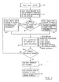
- Figure 1 shows the main steps involved in generating a testcase program, these steps are executed in the main processing device of the digital data display system.
- the process involved in this generation is referred to as the testcase generator.
- Figure 1 box 10 shows that the initial step for the user is to enter, into the digital display system control information for the particular run. This will include the weighting factors for the types of instruction to appear in the testcase program, an indication of the total number of instructions of the testcase program, and the number of alphanumeric and graphic display blocks to be produced.
- the information is entered into the system at a terminal display device such as the IBM 3279 colour display. (IBM is a Registered Trade Mark.) As soon as the information is entered then the next process 12 is begun.
- Process 12 is to generate the statements of the testcase program, predict their operation and values of variables and store the text of the statements on a direct access file for later re-ordering. Details of the generation will be described with reference to Figure 2 below.
- Process 14 is the production of an output summary which includes as a comment in the testcase program details of the contents of the generated testcase program including the number of statements and blocks generated and the frequency of various types of statement or block.
- This summary can be accumulative and can give a picture of the contents of a suite of testcase programs.
- the final process 16 is the output of the generated testcase program as a program stored in a disc file attached to the system where it is ready to be used to test the system.
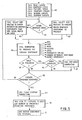
- FIG 2 is a flow chart which shows the steps of the 'generate test program' process 12 of Figure 1 in more detail.
- the first Step 20 is to generate an external procedure statement for the testcase program. This will be standard for the particular programming language employed. For PL/ I this will be of the form:- Program name followed by:- PROCEDURE OPTIONS (MAIN).
- the next Step 22 is to determine whether the next block of statements to be generated will be for a graphic or an alphanumeric display. The decision will be taken on a random basis with a weighting determined by the input control information entered at Step 10 ( Figure 1). If the decision is to generate an alphanumeric block then process Step 24 is entered. If the decision is for a graphic block then process Step 26 is entered. Step 24 is described in more detail below with reference to Figures 3 and 4. Step 26 is described below in more detail with reference to Figures 5 and 6.
- Step 28 is to determine whether or not enough blocks for the particular testcase have been generated. The information for this decision is input as part of Step 10 ( Figure 1). If the required number of blocks has not been generated then Step 22 is re-entered. If there are enough then Step 30 is entered.
- Step 30 is to generate the standard routines for error handling, providing a frame for a displayed picture and a backing grid for a graphic display. Although these routines are not necessarily generated for each testcase, the routines themselves are not random.
- the final Step 32 is to generate an external end statement.
- Figure 3 shows the main steps in the Execute Main Alphanumeric Logic process Step 24 ( Figure 2).
- the main purpose of this process is to generate statements that will result in alphanumeric data being displayed at a terminal with certain characters that will be identified by a user and either overwritten by typing into a keyboard or designated by using a light pen directed at the screen. All modified fields are sent back to the testcase and checked. If they are incorrect an error condition is signalled.
- the first Step 40 is to call a Page Create subroutine.
- This routine provides the text of a page create statement.
- the statement defines how many rows and columns are to be used in the page and internal control blocks in the generator, which are used to ensure that generated statements are executable, are set to reflect these parameters.
- Step 41 is to call a subroutine to add a random number of field declarations to the testcase.
- the subroutine is given the title FIELD DECLARE and is called at this point in the process to ensure that when statements are generated randomly later on there will always be at least one valid field declaration.
- Step 42 is to determine whether or not the page type created at Step 40 permits character attribute statements. If not Step 43 is entered; if yes Step 44 is entered.
- Step 43 is to call a subroutine called SELECT to choose between all alphanumeric statements except those involving character attributes.
- Step 44 calls the SELECT subroutine to choose one statement from all the alphanumeric statements.
- Step 45 calls the specific statement generation subroutine to generate the chosen statement.
- the generation of different statements involves similar processes.
- Figure 4 shows an example of the generation of the alphanumeric PUT statement and will be described below.
- Step 46 is entered to determine whether or not enough statements have been generated. If not then Step 42 is re-entered. If yes then Step 47 is entered. Step 47 is to add a READ statement to the testcase and Step 48 is to add checking code to the testcase to check that all echoed fields arrive correctly.
- FIG 4 is a flow chart of the process involved in generating an alphanumeric PUT statement.
- the first Step 50 in the process is to randomly choose one of the already defined alphanumeric fields (Step 41, Figure 3).
- Step 52 is to choose a numeric check character, that will eventually appear in the display screen for the user to overwrite and be 'echoed' back when the Read statement (Step 47, Figure 3) is executed.
- Step 53 the decision is taken to enter Step 54 which sets the check character to the 1 # 1 symbol.
- Step 55 If the field is a 'deferred light pen' type then the decision at Step 55 is to enter Step 56 and set the check character to the symbol '!'.
- Step 57 is entered. Step 57 is to choose a random check character then choose the length of data and position in the field of the echo prompt character.
- Step 58 is entered.
- Step 58 is to construct the text of the PUT statement and add it to the testcase.
- Step 59 which updates the testcase generator's internal dictionary so that the checking of the echoed data can be monitored efficiently.
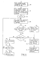
- Figure 5 shows the main steps in the execute main graphics logic step (26, Figure 2).
- the first step 60 in the process is to create the various parameters that are needed to define a graphics display. These are created by calling a series of subroutines which generate first of all the page create parameters which are similar to the page create routine of the alphanumeric process. Other routines define the graphics field, the picture space, the viewport and window to be used and the segment in which the graphic picture is to be drawn.
- Step 61 in the process is to decide whether or not a graphics area is in the process of being constructed. For the first statement generated the answer to this question will always be no and Step 62 will then be entered.
- Step 62 is a process to determine which graphic statement should be produced. This is done on a weighted random generator basis. If in Step 61 it had been determined that a graphics area was in the process of being constructed, Step 63 is entered to choose between graphic statements that are valid inside a graphics area.
- Step 64 calls the routine to generate the chosen statement.
- the generation of the arc statement which is typical of generation of other primitive lines is described below with reference to Figure 6.
- Step 65 is entered to determine whether or not an area is still being constructed. If the answer is yes then Step 66 is to determine whether or not the area is completed. If the area is complete then Step 67 is entered which is a routine to add the end area statement to the testcase. If the decision made in Step 65 or 66 is no then Step 68 is entered. Step 68 is also entered at the conclusion of Step 67.
- Step 68 is to determine whether or not enough statements have already been generated. If there have not been enough then Step 61 is re-entered. If there have been enough then Step 69 is entered. Step 69 is a process to close the segment which was created in Step 60. This is followed at Step 70 which adds the statements to the testcase to send out markers at predicted primitive endpoints. Step 71 follows which adds an output statement to the testcase.
- Figure 6 is a flowchart of the process involved in generating an ARC statement.
- an arc is defined as a sweep of X degrees starting at one endpoint with a defined centre point.
- the first Step 80 in the process is therefore to choose a centre of the arc, by using a random number generator to provide valid co-ordinate points.
- the second Step 81 is to use the random number generator to choose how many degrees of sweep the arc should contain.
- Steps 82-89 are concerned with this checking.
- Step 82 is to initially set X (the number of degrees of sweep) to 10.
- Step 83 is to calculate the endpoint of the arc with a sweep of X degrees.
- Step 84 is to calculate whether the endpoint is inside the window. If the answer is no then Step 85 is to reduce the value of X to a valid value. This is achieved by subtracting a number from 10 to 19 randomly chosen from the current value of X. If the endpoint is within the window then Step 86 is to determine whether or not X equals the proposed sweep chosen at Step 81.
- Steps 90 and 91 are entered. If not then Step 87 adds 10 degrees to the value of X. Step 88 determines whether or not X is greater than the proposed sweep, if no then Step 83 is re-entered; if yes then Step 89 sets X equal to the number chosen at Step 81 before Step 83 is re-entered.
- Step 90 is to create the text of the ARC statement and add it to the testcase.
- Step 91 is concerned with adding the predicted endpoint to an array of endpoints held in the testcase generator.
- testcase generator When a primitive (line or arc) is generated the testcase generator adds the co-ordinates of the primitive's predicted endpoint to an array. These co-ordinates are then used to generate endpoint marker symbols which are transmitted to the display device by a statement in the testcase immediately prior to the READ. The marker symbols should all occur at the endpoints of lines on the display. A visual check will indicate whether or not this is the case. Obviously a marker symbol unattached to a line or a line without a marker symbol indicates an error in the system.
- Figure 7 illustrates a typical graphical testcase output as it appears on a display screen.
- the area 100 is the window defined at Step 60 ( Figure 5).
- the subroutine chosen initially at Step 62 ( Figure 5) is assumed to be an AREA, consequently the succeeding primitives will then define an area.
- 101 is the starting point and the first primitive drawn is an arc which ends at point 102. Marker symbols shown on the drawing as asterisks are generated for the points 101 and 102.
- the second primitive is an arc which ends at point 103. From the position of 103 adjacent to the edge of the window 100 it is likely that the definition of the arc required the adjustment of the degree of sweep.
- Two solid lines then join points 103, 104 and 105 and a dashed line joins 105 to 106. After the generation of the dashed line the area-end routine closes the area by joining 106 and 101 and the enclosed areas are shaded in the appropriate colour.
- a visual inspection will show whether the marker symbols appear at the correct place and also whether any primitive extends beyond the window area. A further check can be made on the area shading to ensure there is no over or underspill of colour.
- testcase generator adds the X, Y co-ordinates of the endpoints to an array.
- graphic block is sent out to the display terminal composite marker symbols are also sent to each of the predicted endpoints.
- Each marker symbol has a yellow and black portion to ensure that it will be visible whatever the background colour.
- the testcase generator maintains a dictionary for the block.
- Each declared field in the block has an entry in the dictionary.
- the entry will include the field attributes such as starting row and column, width, depth etc.
- the dictionary entry will include this number and also which data character is the echo-prompt character.
- the entry will reflect this information. It will also indicate whether the echo-prompt is to be overwritten or modified with a light pen.
- testcase generator dictionary When the alpha block is put out to the display the testcase generator dictionary will have an entry for all fields in that block. When the modified fields are then read back to the processor from the display the generated testcase checks that all fields that were sent out with echo-prompt characters have been correctly modified and returned to the testcase. The tests to check the modification use the data held in the dictionary to determine the position of the prompt character.
Landscapes
- Engineering & Computer Science (AREA)
- Theoretical Computer Science (AREA)
- Physics & Mathematics (AREA)
- General Engineering & Computer Science (AREA)
- General Physics & Mathematics (AREA)
- Quality & Reliability (AREA)
- Computer Hardware Design (AREA)
- Human Computer Interaction (AREA)
- Input From Keyboards Or The Like (AREA)
- Debugging And Monitoring (AREA)
- Digital Computer Display Output (AREA)
Priority Applications (3)
| Application Number | Priority Date | Filing Date | Title |
|---|---|---|---|
| EP80304231A EP0052684B1 (de) | 1980-11-26 | 1980-11-26 | Testverfahren für eine Anzeigseinrichtung |
| DE8080304231T DE3071062D1 (en) | 1980-11-26 | 1980-11-26 | A method of testing a display apparatus |
| US06/318,296 US4464655A (en) | 1980-11-26 | 1981-11-05 | Testcase generator with marker symbols displayed with primary data |
Applications Claiming Priority (1)
| Application Number | Priority Date | Filing Date | Title |
|---|---|---|---|
| EP80304231A EP0052684B1 (de) | 1980-11-26 | 1980-11-26 | Testverfahren für eine Anzeigseinrichtung |
Publications (2)
| Publication Number | Publication Date |
|---|---|
| EP0052684A1 true EP0052684A1 (de) | 1982-06-02 |
| EP0052684B1 EP0052684B1 (de) | 1985-09-04 |
Family
ID=8187314
Family Applications (1)
| Application Number | Title | Priority Date | Filing Date |
|---|---|---|---|
| EP80304231A Expired EP0052684B1 (de) | 1980-11-26 | 1980-11-26 | Testverfahren für eine Anzeigseinrichtung |
Country Status (3)
| Country | Link |
|---|---|
| US (1) | US4464655A (de) |
| EP (1) | EP0052684B1 (de) |
| DE (1) | DE3071062D1 (de) |
Cited By (2)
| Publication number | Priority date | Publication date | Assignee | Title |
|---|---|---|---|---|
| EP0413133A3 (en) * | 1989-08-16 | 1992-02-26 | International Business Machines Corporation | Service processor tester |
| EP0645711A1 (de) * | 1993-09-17 | 1995-03-29 | Siemens Aktiengesellschaft | Verfahren zum Betrieb eines Datensichtgerätes und Einrichtungen zur Durchführung des Verfahrens |
Families Citing this family (9)
| Publication number | Priority date | Publication date | Assignee | Title |
|---|---|---|---|---|
| JPS6074003A (ja) * | 1983-09-30 | 1985-04-26 | Ryozo Setoguchi | 形状創成装置 |
| US4775857A (en) * | 1985-05-17 | 1988-10-04 | Honeywell Inc. | On-line verification of video display generator |
| US4903012A (en) * | 1987-01-20 | 1990-02-20 | Alps Electric Co., Ltd. | Coordinate system input device providing registration calibration and a mouse function |
| US5309174A (en) * | 1987-10-13 | 1994-05-03 | Motorola, Inc. | Electronic display system |
| CA1331811C (en) * | 1987-10-13 | 1994-08-30 | Loren Stuart Minkus | Electronic display system |
| JP3679422B2 (ja) * | 1992-10-21 | 2005-08-03 | キヤノン株式会社 | 定着装置 |
| US6063132A (en) * | 1998-06-26 | 2000-05-16 | International Business Machines Corporation | Method for verifying design rule checking software |
| US7057630B2 (en) * | 2003-01-24 | 2006-06-06 | Microsoft Corporation | System and method for determining display subsystem compliance |
| CN104978245A (zh) * | 2015-06-24 | 2015-10-14 | 福州瑞芯微电子有限公司 | 一种显示屏在线诊断的方法及其系统 |
Citations (3)
| Publication number | Priority date | Publication date | Assignee | Title |
|---|---|---|---|---|
| GB1441418A (en) * | 1972-09-23 | 1976-06-30 | Ibm | Indicating addressing errors on output devices in data processing systems |
| GB1510240A (en) * | 1976-11-25 | 1978-05-10 | Ibm | Method of operating a computer to produce test case programmes |
| EP0009828A2 (de) * | 1978-10-11 | 1980-04-16 | Westinghouse Electric Corporation | Digital-Sichtanzeigeübungsanordnung |
Family Cites Families (4)
| Publication number | Priority date | Publication date | Assignee | Title |
|---|---|---|---|---|
| US3286083A (en) * | 1962-04-16 | 1966-11-15 | Ibm | Information storage system |
| US3753032A (en) * | 1971-07-27 | 1973-08-14 | United Aircraft Corp | Crt with built-in display registration test |
| US3742288A (en) * | 1971-09-08 | 1973-06-26 | Bunker Ramo | Raster control device for controlling the positioning of the raster at the beginning of each new line |
| US4295135A (en) * | 1978-12-18 | 1981-10-13 | Josef Sukonick | Alignable electronic background grid generation system |
-
1980
- 1980-11-26 EP EP80304231A patent/EP0052684B1/de not_active Expired
- 1980-11-26 DE DE8080304231T patent/DE3071062D1/de not_active Expired
-
1981
- 1981-11-05 US US06/318,296 patent/US4464655A/en not_active Expired - Fee Related
Patent Citations (3)
| Publication number | Priority date | Publication date | Assignee | Title |
|---|---|---|---|---|
| GB1441418A (en) * | 1972-09-23 | 1976-06-30 | Ibm | Indicating addressing errors on output devices in data processing systems |
| GB1510240A (en) * | 1976-11-25 | 1978-05-10 | Ibm | Method of operating a computer to produce test case programmes |
| EP0009828A2 (de) * | 1978-10-11 | 1980-04-16 | Westinghouse Electric Corporation | Digital-Sichtanzeigeübungsanordnung |
Cited By (2)
| Publication number | Priority date | Publication date | Assignee | Title |
|---|---|---|---|---|
| EP0413133A3 (en) * | 1989-08-16 | 1992-02-26 | International Business Machines Corporation | Service processor tester |
| EP0645711A1 (de) * | 1993-09-17 | 1995-03-29 | Siemens Aktiengesellschaft | Verfahren zum Betrieb eines Datensichtgerätes und Einrichtungen zur Durchführung des Verfahrens |
Also Published As
| Publication number | Publication date |
|---|---|
| US4464655A (en) | 1984-08-07 |
| EP0052684B1 (de) | 1985-09-04 |
| DE3071062D1 (en) | 1985-10-10 |
Similar Documents
| Publication | Publication Date | Title |
|---|---|---|
| Bird et al. | Automatic generation of random self-checking test cases | |
| US5732277A (en) | Graphical system for modelling a process and associated method | |
| US5450545A (en) | Generation of rules-based computer programs using data entry screens | |
| US6421822B1 (en) | Graphical user interface for developing test cases using a test object library | |
| US5852564A (en) | Method and apparatus for interactively displaying signal information during computer simulation of an electrical circuit | |
| US5610828A (en) | Graphical system for modelling a process and associated method | |
| US5161211A (en) | Method and system of specification processing | |
| EP0242131B1 (de) | Grafiksystem zum Modellieren eines Prozesses und dazugehöriges Verfahren | |
| US5926638A (en) | Program debugging system for debugging a program having graphical user interface | |
| JP3195839B2 (ja) | 発電所の施設の運転を監視する方法 | |
| US20020029377A1 (en) | System and method for developing test cases using a test object library | |
| US5438526A (en) | Program generation method for particles simulation | |
| EP0213347A2 (de) | Simulation von externen Rechnerprogrammschnittstellen | |
| US4464655A (en) | Testcase generator with marker symbols displayed with primary data | |
| US4617643A (en) | Syntax error correction method and apparatus | |
| US11023359B2 (en) | Automated API generation | |
| Allen et al. | Input/output software capability for a man-machine comunication and image processing system | |
| US5319579A (en) | Simulation of human performance of a process operation procedure | |
| JPH0756768A (ja) | データ型対応の自動テスト方法 | |
| JPS646468B2 (de) | ||
| JPH07152550A (ja) | オブジェクト指向システムの作成方法 | |
| Ebrahimi | VPCL: A visual language for teaching and learning programming.(A picture is worth a thousand words) | |
| Goltz | DARE-I, An on-line digital simulation system | |
| Maurer | Full-screen testing of interactive applications | |
| Kahro et al. | A control computer software production system |
Legal Events
| Date | Code | Title | Description |
|---|---|---|---|
| PUAI | Public reference made under article 153(3) epc to a published international application that has entered the european phase |
Free format text: ORIGINAL CODE: 0009012 |
|
| AK | Designated contracting states |
Designated state(s): DE FR GB |
|
| 17P | Request for examination filed |
Effective date: 19820623 |
|
| GRAA | (expected) grant |
Free format text: ORIGINAL CODE: 0009210 |
|
| AK | Designated contracting states |
Designated state(s): DE FR GB |
|
| REF | Corresponds to: |
Ref document number: 3071062 Country of ref document: DE Date of ref document: 19851010 |
|
| ET | Fr: translation filed | ||
| PLBE | No opposition filed within time limit |
Free format text: ORIGINAL CODE: 0009261 |
|
| STAA | Information on the status of an ep patent application or granted ep patent |
Free format text: STATUS: NO OPPOSITION FILED WITHIN TIME LIMIT |
|
| 26N | No opposition filed | ||
| PGFP | Annual fee paid to national office [announced via postgrant information from national office to epo] |
Ref country code: GB Payment date: 19901012 Year of fee payment: 11 |
|
| PGFP | Annual fee paid to national office [announced via postgrant information from national office to epo] |
Ref country code: FR Payment date: 19901020 Year of fee payment: 11 |
|
| PGFP | Annual fee paid to national office [announced via postgrant information from national office to epo] |
Ref country code: DE Payment date: 19901124 Year of fee payment: 11 |
|
| PG25 | Lapsed in a contracting state [announced via postgrant information from national office to epo] |
Ref country code: GB Effective date: 19911126 |
|
| GBPC | Gb: european patent ceased through non-payment of renewal fee | ||
| PG25 | Lapsed in a contracting state [announced via postgrant information from national office to epo] |
Ref country code: FR Effective date: 19920731 |
|
| PG25 | Lapsed in a contracting state [announced via postgrant information from national office to epo] |
Ref country code: DE Effective date: 19920801 |
|
| REG | Reference to a national code |
Ref country code: FR Ref legal event code: ST |