EP0052422A2 - Wärmeaustauscher - Google Patents
Wärmeaustauscher Download PDFInfo
- Publication number
- EP0052422A2 EP0052422A2 EP81304782A EP81304782A EP0052422A2 EP 0052422 A2 EP0052422 A2 EP 0052422A2 EP 81304782 A EP81304782 A EP 81304782A EP 81304782 A EP81304782 A EP 81304782A EP 0052422 A2 EP0052422 A2 EP 0052422A2
- Authority
- EP
- European Patent Office
- Prior art keywords
- pipework
- ducts
- heat exchanger
- sheet
- exchanger according
- Prior art date
- Legal status (The legal status is an assumption and is not a legal conclusion. Google has not performed a legal analysis and makes no representation as to the accuracy of the status listed.)
- Granted
Links
Images
Classifications
-
- F—MECHANICAL ENGINEERING; LIGHTING; HEATING; WEAPONS; BLASTING
- F28—HEAT EXCHANGE IN GENERAL
- F28D—HEAT-EXCHANGE APPARATUS, NOT PROVIDED FOR IN ANOTHER SUBCLASS, IN WHICH THE HEAT-EXCHANGE MEDIA DO NOT COME INTO DIRECT CONTACT
- F28D7/00—Heat-exchange apparatus having stationary tubular conduit assemblies for both heat-exchange media, the media being in contact with different sides of a conduit wall
- F28D7/08—Heat-exchange apparatus having stationary tubular conduit assemblies for both heat-exchange media, the media being in contact with different sides of a conduit wall the conduits being otherwise bent, e.g. in a serpentine or zig-zag
-
- F—MECHANICAL ENGINEERING; LIGHTING; HEATING; WEAPONS; BLASTING
- F28—HEAT EXCHANGE IN GENERAL
- F28D—HEAT-EXCHANGE APPARATUS, NOT PROVIDED FOR IN ANOTHER SUBCLASS, IN WHICH THE HEAT-EXCHANGE MEDIA DO NOT COME INTO DIRECT CONTACT
- F28D20/00—Heat storage plants or apparatus in general; Regenerative heat-exchange apparatus not covered by groups F28D17/00 or F28D19/00
- F28D20/003—Heat storage plants or apparatus in general; Regenerative heat-exchange apparatus not covered by groups F28D17/00 or F28D19/00 using thermochemical reactions
-
- F—MECHANICAL ENGINEERING; LIGHTING; HEATING; WEAPONS; BLASTING
- F28—HEAT EXCHANGE IN GENERAL
- F28D—HEAT-EXCHANGE APPARATUS, NOT PROVIDED FOR IN ANOTHER SUBCLASS, IN WHICH THE HEAT-EXCHANGE MEDIA DO NOT COME INTO DIRECT CONTACT
- F28D7/00—Heat-exchange apparatus having stationary tubular conduit assemblies for both heat-exchange media, the media being in contact with different sides of a conduit wall
- F28D7/08—Heat-exchange apparatus having stationary tubular conduit assemblies for both heat-exchange media, the media being in contact with different sides of a conduit wall the conduits being otherwise bent, e.g. in a serpentine or zig-zag
- F28D7/082—Heat-exchange apparatus having stationary tubular conduit assemblies for both heat-exchange media, the media being in contact with different sides of a conduit wall the conduits being otherwise bent, e.g. in a serpentine or zig-zag with serpentine or zig-zag configuration
- F28D7/085—Heat-exchange apparatus having stationary tubular conduit assemblies for both heat-exchange media, the media being in contact with different sides of a conduit wall the conduits being otherwise bent, e.g. in a serpentine or zig-zag with serpentine or zig-zag configuration in the form of parallel conduits coupled by bent portions
-
- F—MECHANICAL ENGINEERING; LIGHTING; HEATING; WEAPONS; BLASTING
- F28—HEAT EXCHANGE IN GENERAL
- F28D—HEAT-EXCHANGE APPARATUS, NOT PROVIDED FOR IN ANOTHER SUBCLASS, IN WHICH THE HEAT-EXCHANGE MEDIA DO NOT COME INTO DIRECT CONTACT
- F28D9/00—Heat-exchange apparatus having stationary plate-like or laminated conduit assemblies for both heat-exchange media, the media being in contact with different sides of a conduit wall
- F28D9/04—Heat-exchange apparatus having stationary plate-like or laminated conduit assemblies for both heat-exchange media, the media being in contact with different sides of a conduit wall the conduits being formed by spirally-wound plates or laminae
-
- Y—GENERAL TAGGING OF NEW TECHNOLOGICAL DEVELOPMENTS; GENERAL TAGGING OF CROSS-SECTIONAL TECHNOLOGIES SPANNING OVER SEVERAL SECTIONS OF THE IPC; TECHNICAL SUBJECTS COVERED BY FORMER USPC CROSS-REFERENCE ART COLLECTIONS [XRACs] AND DIGESTS
- Y02—TECHNOLOGIES OR APPLICATIONS FOR MITIGATION OR ADAPTATION AGAINST CLIMATE CHANGE
- Y02E—REDUCTION OF GREENHOUSE GAS [GHG] EMISSIONS, RELATED TO ENERGY GENERATION, TRANSMISSION OR DISTRIBUTION
- Y02E60/00—Enabling technologies; Technologies with a potential or indirect contribution to GHG emissions mitigation
- Y02E60/14—Thermal energy storage
Definitions
- This invention related to heat exchangers suitable for use in systems using an adsorber as a source of heat.
- This comprises a continuous pipework through which liquid can pass, the pipework being supported on a structure and provided with ducts with pervious walls spaced from and adjacent to the pipework. There are also means capable of housing solid material adjacent to, but external of these ducts.
- the pipework and structure are made of heat conducting material, e.g. a metal such as copper or aluminium.
- the pipework is supported on a heat conducting structure and this is preferably a sheet, strip or plate. It is convenient for the pipework to be soldered or welded onto this structure e.g. sheet. However if desired this structure e.g. sheet may be made with expanded sections which form liquid-tight conduits therein and hence constitute the pipework. It is essential that the structure itself is also made of heat conducting material, e.g. a metal such as copper or aluminium.
- the configuration of the pipework can vary, but usually it is of a serpentine shape, whereby if a structure, e.g. sheet, is used it is substantially covered with pipework. When installed for use it is preferred that the axes of the bulk of the pipework are substantially vertical.
- ducts with pervious walls Spaced from and adjacent to the pipework are ducts with pervious walls. These ducts can for example be perforated strips or wire mesh. Other examples are porous plastics or metals. Preferably the ducts are made of heat conducting material, e.g. copper or aluminium.
- the ducts need only be attached to one surface of the structure.
- These ducts can conveniently be half-cylinders or be U-shaped or rectangular or square in cross-section. Together with the structure they will form a pervious passageway surrounding the pipework.
- These ducts can be attached to the supporting structure by for example welding, soldering or glue such as epoxy resin adhesive, etc.
- substantially all the pipework has pervious ducts associated therewith.
- pervious ducts associated therewith.
- the means capable of housing solid material adjacent to, but external of the ducts can take various forms.
- One particularly convenient form is provided by the use of a plurality of structures in the form of sheet, strips or plates substantially parallel to each other housed in a container.
- the structures are placed substantially vertically in the container substantially parallel to one another and the solid material is housed between each structure and supported by the bottom of the container.
- Some of the solid material is of course housed between the side walls of the container and the structure immediately adjacent to the side walls of the container. In such cases, the surfaces of the structures having the pipework attached thereto, will usually but not necessarily face in the same direction.
- each sheet, strip or plate could be attached to each sheet, strip or plate so that solid material can be housed adjacent to each duct.
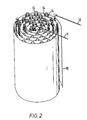
- Another particularly suitable form is provided by the use of a structure in the form of a spiral sheet housed in a container.
- This sheet is a continuous spiral, one face of which is provided with a continuous pipework surrounded by a series of pervious ducts. The space in between is used to house the solid material which is supported by the bottom of the container.
- each structure it is preferred that the pipework associated with each structure be connected in parallel, e.g. by manifolds, connected respectively to the inlet ends and to the outlet ends of each pipework.
- the spacing between adjacent structures or adjacent laps of the spiral sheet should be chosen so as to give adequate heat transfer whilst minimising the amount of heat conducting material, e.g. metal, used for the purpose.
- electrical resistance heaters e.g. in the form of metal tube enclosing electric elements
- the supporting structure e.g. sheet or plate.
- electrical resistance heaters which of course should be electrically insulated from the structure can be spaced at regular intervals throughout the supporting structure or if desired only at certain positions on the supporting structure.
- more than one continuous pipework supported on a structure can be used in any one heat exchanger, thus enabling more than one liquid to be subjected to heat exchange. If two pipeworks are required then one convenient arrangement would be the use of a sheet or plate as the supporting structure with one face supporting one pipework and the other face supporting the other pipework.
- the above described heat exchangers are particularly designed for cases where solid material containing a vapour is housed in the heat exchanger adjacent to, but external of the ducts.
- the vapour is driven off from the solid, passing through the pervious ducts and out through an outlet, by the heat given up by liquid circulating through the pipework.
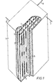
- the outer container houses a number of parallel sheets, one of which is shown at 2. Soldered to each of these sheets is a pipework of serpentine shape, two portions of which are shown at 4. Adjacent to the bulk of the pipework are a series of porous ducts, two of which are shown at 3. These consist of wire gauze shaped substantially as half cylinders and are fixed onto the sheets 2 so as to enclose the parallel portions of the serpentine pipework 4, but leaving a small space between the pipework and the gauze.
- each pipework is connected in parallel by manifolds 6 and 7, one of which is the inlet 6 and the other the outlet 7 for liquid flowing through the pipework 4. There is an outlet for vapour at 8.
- each sheet 2 is filled with a solid material 5 which may for example be an adsorbent such as zeolite.
- a solid material 5 which may for example be an adsorbent such as zeolite.
- the heat exchanger operates by passing heated liquid through the inlet 6 and out of the outlet 7 wherein heat will be transferred to the solid material 5. Any vapour present therein, e.g. water vapour, will be heated and some of it will be vaporised passing through the wire gauze ducts 3 and finally leaving the container 1 through the outlet 8.
- Any vapour present therein e.g. water vapour, will be heated and some of it will be vaporised passing through the wire gauze ducts 3 and finally leaving the container 1 through the outlet 8.
- the continuous serpentine pipework 13 is supported on a coiled sheet 10.
Landscapes
- Engineering & Computer Science (AREA)
- Physics & Mathematics (AREA)
- Thermal Sciences (AREA)
- Mechanical Engineering (AREA)
- General Engineering & Computer Science (AREA)
- Chemical & Material Sciences (AREA)
- Chemical Kinetics & Catalysis (AREA)
- General Chemical & Material Sciences (AREA)
- Sorption Type Refrigeration Machines (AREA)
- Heat-Exchange Devices With Radiators And Conduit Assemblies (AREA)
Applications Claiming Priority (2)
| Application Number | Priority Date | Filing Date | Title |
|---|---|---|---|
| GB8036901A GB2088038B (en) | 1980-11-18 | 1980-11-18 | Heat exchanger |
| GB8036901 | 1980-11-18 |
Publications (3)
| Publication Number | Publication Date |
|---|---|
| EP0052422A2 true EP0052422A2 (de) | 1982-05-26 |
| EP0052422A3 EP0052422A3 (en) | 1982-12-01 |
| EP0052422B1 EP0052422B1 (de) | 1987-11-25 |
Family
ID=10517375
Family Applications (1)
| Application Number | Title | Priority Date | Filing Date |
|---|---|---|---|
| EP81304782A Expired EP0052422B1 (de) | 1980-11-18 | 1981-10-14 | Wärmeaustauscher |
Country Status (4)
| Country | Link |
|---|---|
| EP (1) | EP0052422B1 (de) |
| DE (1) | DE3176545D1 (de) |
| ES (1) | ES507213A0 (de) |
| GB (1) | GB2088038B (de) |
Cited By (3)
| Publication number | Priority date | Publication date | Assignee | Title |
|---|---|---|---|---|
| US6997242B2 (en) * | 2000-03-07 | 2006-02-14 | Kabushiki Kaisha Toyoda Jidoshokki Seisakusho | Reservoir with hydrogen storage material |
| EP2971932A4 (de) * | 2013-03-14 | 2016-09-07 | Res Triangle Inst | Gasspeichermodule sowie vorrichtungen, systeme und verfahren mit adsorptionsmitteln |
| EP3382313A1 (de) * | 2017-03-29 | 2018-10-03 | Ostbayerische Technische Hochschule Regensburg | Wärmetauscher |
Families Citing this family (3)
| Publication number | Priority date | Publication date | Assignee | Title |
|---|---|---|---|---|
| DE3347700C2 (de) * | 1983-12-31 | 1994-07-07 | Zeolith Tech | Zeolithformling mit hoher Wärmeleitung und Verfahren zur Herstellung |
| GB2327751A (en) * | 1997-07-23 | 1999-02-03 | Zafer Muhittin Ure | Thermal storage |
| DE102024105227A1 (de) * | 2024-02-23 | 2025-08-28 | LSF Beteiligungs GmbH | Thermischer Energiespeicher |
Family Cites Families (6)
| Publication number | Priority date | Publication date | Assignee | Title |
|---|---|---|---|---|
| BE379820A (de) * | 1930-05-14 | |||
| US2024083A (en) * | 1931-11-21 | 1935-12-10 | Young Arthur Ephraim | Refrigeration system |
| GB1581639A (en) * | 1976-08-13 | 1980-12-17 | Johnson Matthey Co Ltd | Storage of gas |
| SE411457C (sv) * | 1977-12-14 | 1986-06-23 | Hans Ivar Wallsten | Anvendning i en vermeackumulator av en i fibrost berarmaterial fixerad sorbent |
| DE3016290A1 (de) * | 1979-04-30 | 1980-11-20 | Hans Ivar Wallsten | Stabile formlinge aus sorbens und verfahren zu ihrer herstellung |
| US4309980A (en) * | 1980-03-07 | 1982-01-12 | Thermal Energy Storage, Inc. | Closed vaporization heat transfer system |
-
1980
- 1980-11-18 GB GB8036901A patent/GB2088038B/en not_active Expired
-
1981
- 1981-10-14 DE DE8181304782T patent/DE3176545D1/de not_active Expired
- 1981-10-14 EP EP81304782A patent/EP0052422B1/de not_active Expired
- 1981-11-17 ES ES507213A patent/ES507213A0/es active Granted
Cited By (3)
| Publication number | Priority date | Publication date | Assignee | Title |
|---|---|---|---|---|
| US6997242B2 (en) * | 2000-03-07 | 2006-02-14 | Kabushiki Kaisha Toyoda Jidoshokki Seisakusho | Reservoir with hydrogen storage material |
| EP2971932A4 (de) * | 2013-03-14 | 2016-09-07 | Res Triangle Inst | Gasspeichermodule sowie vorrichtungen, systeme und verfahren mit adsorptionsmitteln |
| EP3382313A1 (de) * | 2017-03-29 | 2018-10-03 | Ostbayerische Technische Hochschule Regensburg | Wärmetauscher |
Also Published As
| Publication number | Publication date |
|---|---|
| EP0052422B1 (de) | 1987-11-25 |
| GB2088038B (en) | 1984-12-05 |
| DE3176545D1 (en) | 1988-01-07 |
| EP0052422A3 (en) | 1982-12-01 |
| ES8305487A1 (es) | 1983-04-01 |
| ES507213A0 (es) | 1983-04-01 |
| GB2088038A (en) | 1982-06-03 |
Similar Documents
| Publication | Publication Date | Title |
|---|---|---|
| US4262653A (en) | Solar energy heat storage and transfer system | |
| US4072142A (en) | Heat absorber for solar energy | |
| US4297990A (en) | Solar collector | |
| US2812165A (en) | Header units for plate type heat exchanger | |
| MY112139A (en) | Heat exchanger element and heat exchanger using same | |
| EP0052422A2 (de) | Wärmeaustauscher | |
| IT1135337B (it) | Tubo per scambiatori di calore a montaggio meccanico e scambiatore a piastra collettrice comportante detto tubo | |
| US5431149A (en) | Solar energy collector | |
| EP0162828A2 (de) | Wärmetauscher | |
| US3269459A (en) | Extensive surface heat exchanger | |
| US2702334A (en) | Plate heater | |
| EP0177660A1 (de) | Heizkörper | |
| US4653580A (en) | Flow tank heat exchanger | |
| SE7713603L (sv) | Vermevexlare | |
| FR2429988A1 (fr) | Echangeur de chaleur a structure poreuse anisotrope | |
| US4676227A (en) | Solar panel | |
| WO1999067584A1 (en) | Heat exchanger tracking | |
| US2510235A (en) | Portable radiator | |
| CN115507692A (zh) | 一种模块化固体电储热装置 | |
| EP0006949B1 (de) | Heisswasserradiator | |
| US4184478A (en) | Heat exchangers and solar heating | |
| DE3360632D1 (en) | High temperature heat exchanger with a metallic pipe bundle | |
| US4289197A (en) | Heat exchanger | |
| GB2125154A (en) | A heat pump unit | |
| CN119406342B (zh) | 含多温度区的连续型微通道反应系统及温控方法 |
Legal Events
| Date | Code | Title | Description |
|---|---|---|---|
| PUAI | Public reference made under article 153(3) epc to a published international application that has entered the european phase |
Free format text: ORIGINAL CODE: 0009012 |
|
| AK | Designated contracting states |
Designated state(s): BE DE FR GB IT NL SE |
|
| PUAL | Search report despatched |
Free format text: ORIGINAL CODE: 0009013 |
|
| AK | Designated contracting states |
Designated state(s): BE DE FR GB IT NL SE |
|
| 17P | Request for examination filed |
Effective date: 19830419 |
|
| GRAA | (expected) grant |
Free format text: ORIGINAL CODE: 0009210 |
|
| AK | Designated contracting states |
Kind code of ref document: B1 Designated state(s): BE DE FR GB IT NL SE |
|
| ITF | It: translation for a ep patent filed | ||
| REF | Corresponds to: |
Ref document number: 3176545 Country of ref document: DE Date of ref document: 19880107 |
|
| ET | Fr: translation filed | ||
| PLBE | No opposition filed within time limit |
Free format text: ORIGINAL CODE: 0009261 |
|
| STAA | Information on the status of an ep patent application or granted ep patent |
Free format text: STATUS: NO OPPOSITION FILED WITHIN TIME LIMIT |
|
| 26N | No opposition filed | ||
| PG25 | Lapsed in a contracting state [announced via postgrant information from national office to epo] |
Ref country code: GB Effective date: 19891014 |
|
| PG25 | Lapsed in a contracting state [announced via postgrant information from national office to epo] |
Ref country code: SE Effective date: 19891015 |
|
| PG25 | Lapsed in a contracting state [announced via postgrant information from national office to epo] |
Ref country code: BE Effective date: 19891031 |
|
| BERE | Be: lapsed |
Owner name: EXXON RESEARCH AND ENGINEERING CY Effective date: 19891031 |
|
| PG25 | Lapsed in a contracting state [announced via postgrant information from national office to epo] |
Ref country code: NL Effective date: 19900501 |
|
| GBPC | Gb: european patent ceased through non-payment of renewal fee | ||
| NLV4 | Nl: lapsed or anulled due to non-payment of the annual fee | ||
| PG25 | Lapsed in a contracting state [announced via postgrant information from national office to epo] |
Ref country code: FR Effective date: 19900629 |
|
| PG25 | Lapsed in a contracting state [announced via postgrant information from national office to epo] |
Ref country code: DE Effective date: 19900703 |
|
| REG | Reference to a national code |
Ref country code: FR Ref legal event code: ST |
|
| EUG | Se: european patent has lapsed |
Ref document number: 81304782.6 Effective date: 19900705 |