EP0052100B1 - Kraftantriebsreihe mit grossem übersetzungsverhältnisbereich - Google Patents
Kraftantriebsreihe mit grossem übersetzungsverhältnisbereich Download PDFInfo
- Publication number
- EP0052100B1 EP0052100B1 EP81900230A EP81900230A EP0052100B1 EP 0052100 B1 EP0052100 B1 EP 0052100B1 EP 81900230 A EP81900230 A EP 81900230A EP 81900230 A EP81900230 A EP 81900230A EP 0052100 B1 EP0052100 B1 EP 0052100B1
- Authority
- EP
- European Patent Office
- Prior art keywords
- drive line
- gear
- power input
- axis
- recited
- Prior art date
- Legal status (The legal status is an assumption and is not a legal conclusion. Google has not performed a legal analysis and makes no representation as to the accuracy of the status listed.)
- Expired
Links
Images

Classifications
-
- F—MECHANICAL ENGINEERING; LIGHTING; HEATING; WEAPONS; BLASTING
- F16—ENGINEERING ELEMENTS AND UNITS; GENERAL MEASURES FOR PRODUCING AND MAINTAINING EFFECTIVE FUNCTIONING OF MACHINES OR INSTALLATIONS; THERMAL INSULATION IN GENERAL
- F16H—GEARING
- F16H15/00—Gearings for conveying rotary motion with variable gear ratio, or for reversing rotary motion, by friction between rotary members
- F16H15/48—Gearings for conveying rotary motion with variable gear ratio, or for reversing rotary motion, by friction between rotary members with members having orbital motion
- F16H15/50—Gearings providing a continuous range of gear ratios
-
- F—MECHANICAL ENGINEERING; LIGHTING; HEATING; WEAPONS; BLASTING
- F16—ENGINEERING ELEMENTS AND UNITS; GENERAL MEASURES FOR PRODUCING AND MAINTAINING EFFECTIVE FUNCTIONING OF MACHINES OR INSTALLATIONS; THERMAL INSULATION IN GENERAL
- F16H—GEARING
- F16H47/00—Combinations of mechanical gearing with fluid clutches or fluid gearing
- F16H47/06—Combinations of mechanical gearing with fluid clutches or fluid gearing the fluid gearing being of the hydrokinetic type
- F16H47/065—Combinations of mechanical gearing with fluid clutches or fluid gearing the fluid gearing being of the hydrokinetic type the mechanical gearing being of the friction or endless flexible member type
Definitions
- This invention relates to mechanical power transmission systems and more particularly, it concerns an improved drive line or train by which power developed by an engine may be transmitted through a wide range of continuously variable speed ranges.
- automotive drive lines have traditionally included multispeed transmissions to provide a range of speed ratio reductions on the order of 2 or 2.5:1 to 1:1 and a final drive gear reduction at the driving axle approximating 4:1 to provide a total speed reduction range in the drive line on the order of 8 or 10:1 to 4:1.
- the three working bodies may be termed respectively, an "alpha body” which is supported by the transmission frame to be concentric with a first axis, a “beta body” which is concentric with a second axis inclined with respect to and intersecting the first axis at a point of axes intersection, and an "omega body” carried by or forming part of the frame to be concentric also with the first axis.
- any one of these three bodies may be rotatable on the respective axes with which they are concentric, one of the three is held against rotation to provide a reaction torque whereas the other two bodies are rotatable and coupled either directly or by gearing to the respective input and output shafting of the transmission.
- a primary object of the present invention is to provide a highly compact drive line having a wide range of continuously variable speed ratios and which may be accommodated by a relatively small number of easily controlled components.
- an extremely compact automotive drive line is provided by which a wide total range of substantially continuous speed ratios are attainable in two stages or modes of drive line operation to yield a single rotational direction of power output.
- a reverse mode of drive line operation is provided with a single or fixed reduction ratio and a kinetic energy storing flywheel may be included in the drive line to enable the use of both regenerative braking and engine restarting after termination of engine operation when adequate kinetic energy has been stored in the flywheel.
- the transmission includes one working body rotatable on a first axis, another working body rotatable on a second axis revolvable about the first axis and variable means for controlling relative movement of the bodies of these two bodies.
- the planet gear of the gear set is rotatable with and carried by the revolvable body.
- a pair of transmission unit input shafts are connected one directly to the working body rotatable on the first axis and the other directly with the sun gear of the planetary set.
- the respective unit input shafts are connected by coupling devices with a power input in a manner to effect a low drive line speed ratio when the power input is coupled with the sun gear, a high drive line speed ratio range when the power input is coupled with the working body rotatable about the first axis.
- a reverse range is effected by holding the second axis against revolution about the first axis so that the planet gear remains stationary as a reversing idler with a sun gear input and a ring gear output.
- Fig. 1 the structural components of a preferred embodiment of a drive line in accordance with the present invention are shown by which a rotatable power input at a hub 10 is transmitted to a power output at a driven pinion gear 12.
- the hub 10 may be connected directly to the crank shaft of an internal combustion engine, for example. It may be assumed further that the connection of the hub 10 to the engine crank shaft preferably, but not necessarily, is without the customary crank shaft flywheel used to maintain continuity of power impulses developed by a piston-type engine.
- a rigid though multipart external housing 14 includes a CVT unit 16 having concentric inner and outer input shafts 18 and 20.
- the inner shaft 18 is keyed or otherwise coupled for direct rotation with the driven disc 22 of a releasable friction clutch 24 having a hydraulically actuated driving plate assembly 26 coupled with the power input hub 10 by a torque transmitting plate or spider 28.
- the plate 28 is coupled directly and permanently with the driving impeller 30 of a conventional hydraulic torque coupler 32, the output or driven component 34 of which is connected to the outer CVT unit input shaft 20 by an overrunning or freewheeling clutch 36.
- the clutch 36 is conventional and for purposes of the present invention, it is necessary to understand only that the clutch 36 will transmit torque from the coupler 32 to the shaft 20 but will not transmit torque in the opposite direction or from the shaft 20 to the coupler 32. In other words, torque will not be transmitted between the driven member 34 of the coupling 32 and the shaft 20 when the rotational speed of the shaft exceeds that of the member 34.
- a flywheel 38 is splined or otherwise coupled for rotation directly with the outer shaft 20 and although located between the hydraulic coupling 32 and the clutch 24 in the illustrated embodiment, may be located anywhere along the length of the shaft 20.
- Other components included in the illustrated drive line between the hub 10 and the CVT unit 16 include an oil pump 40 connected directly to the input impeller 30 of the hydraulic coupling 32 and thus driven at all times with the power input hub 10 and a light-weight starting ring gear 42 coupled to and supported by the torque plate 28.
- an electric starter motor may be used to drive the ring gear 42 during initial starting of an engine having its crank shaft connected to the hub 10.
- the CVT unit is of a general class disclosed in the previously mentioned U.S. patents. Moreover, certain features of the specific CVT unit illustrated in the drawing form the subject matter of two concurrently filed International Applications WO-A-81/03369 (published 26.11.1981) entitled “Continuously Variable Transmission Unit” and WO-A-81/03366 (published 26.11.1981), entitled “Torque Transmitting Body for Traction Drive Transmissions and Normal Friction Force Developing Method", the name of the inventor in both applications being Yves Jean Kemper. While reference may be made to these concurrently filed International Applications for a more complete description of details and for an explanation of operating principles, the unit 16 will be summarily described herein sufficient for one to understand fully the operation of the illustrated drive line.
- the CVT unit 16 is contained within a generally cylindrical frame 44 bolted or otherwise rigidly connected with the casing 14 and like the transmission units of the class previously described, includes three primary working bodies.
- the first of such bodies is an alpha body 46 supported from the frame 44 by bearings 48 and 50 to be rotatable about a first transmission axis 51;
- the second is a biconical beta body 52 supported rotatably by the alpha body 46 by way of bearings 54 and 56 for rotation about a second axis 58;
- the third is an omega body constituted by a pair of omega rings 60 and 62 which are coupled against rotation by the frame 44 but which are slidable axially along the first axis 51.
- the beta body 52 in the illustrated embodiment is an integral component defining a pair of oppositely convergent, frusto-conical, rolling or traction surfaces 62 and 64 of revolution about the second axis 58.
- the omega rings 60 and 62 define interior rolling or traction surfaces 66 and 68 of revolution about the first axis 51.
- the second axis 58 intersects the first axis 51 at a point S of axes intersection and the apical half angle of the conical surfaces 62 and 64 is equal to the angle at which the first and second axes intersect.
- the rolling surfaces 60, 64 and 66, 68 are retained in rolling friction engagement with each other at two diametrically opposite points P1 and P2 in a plane containing the first and second axes 51 and 58.
- the ratio of the radius R w of the surfaces 66 relative to the ratio R b of the conical surfaces 62 and 64 at the points P1 and P2 may be made to vary by moving the omega rings 60 and 62 toward and away from the point S of axes intersection.
- This ratio function or RwlRb is designated herein and in all equations by the Greek letter (p). Movement of the rings 60 and 62 along the axis 51 to vary the radius ratio is effected by an oppositely pitched screw 70 coupled to an appropriate control such as an electric motor.
- the bearings 54 and 56 supporting the beta body 52 from the alpha body 46 are hydrodynamic radial bearings and, as such, are concentric with the second axis 58 at all times. These bearings, however, permit a slight axial freedom of the beta body 52 along the second axis 58 and also allow pivotal freedom in a sphere concentric with each point of bearing support.
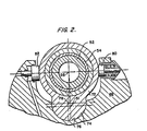
- the bearing 54 at one end of the beta body is carried from the alpha body 46 by an eccentric 72 shown most clearly in Fig. 2.
- the member 72 includes a semicircular lobe 74 which bears against a complementing semicircular recess 76 in the alpha body so that the member 72 is pivotal in relation to the alpha body about an axis 78 which is eccentric to the rotational axis of the alpha body 46 or the first axis 51.
- a semicircular lobe 74 which bears against a complementing semicircular recess 76 in the alpha body so that the member 72 is pivotal in relation to the alpha body about an axis 78 which is eccentric to the rotational axis of the alpha body 46 or the first axis 51.
- a pre-load bias is provided by a spring plunger 80 whereas an unloading plunger 82 actuated by an appropriate hydraulic system (not shown) may be used to hold the beta and omega surfaces out of frictional or torque transmitting engagement with each other.
- the unloading plunger 82 may be used to decouple the traction surfaces 62, 64 and 66, 68 from torque transmitting engagement with each other and thus place the CVT unit 16 in a "neutral" condition.
- Continuously variable speed power transmission in three operating modes is contemplated by the present invention.
- input torque at the outer shaft 20 is transmitted to a sun gear 84 machined integrally on the shaft 20 or otherwise keyed for direct rotation therewith.
- the sun gear 84 meshes with a planet gear 86 rotatable with and carried by the beta body 52 for rotation on the second axis 58 and for orbital movement of the second axis 58 about the first axis 51.
- the planet gear 86 meshes with a bevelled internal ring gear 88 supported by a bearing 90 from the frame 44 for rotation about the first axis 51.
- the ring gear 88 carries a driving pinion 92 which is in mesh at all times with the output pinion 12. The characteristics of this mode of operation are described fully in the aforementioned WO-A-81/03369.
- a second mode of operation torque at the inner shaft 18 is transmitted directly to the alpha body 46 as a result of the inner shaft 18 being splined for rotation with the alpha body 46.
- power is transmitted by movement of the planet gear 86 to the ring gear 88 as a result of movement of the planet gear which is a combination of orbital movement at the speed (a) of the alpha body 46 and rotational movement of the beta body or (A) about the second axis 58.
- the unit 16 operates as a speed reducer in separate but substantially contiguous ranges of continuously variable speed ratios and in which the output pinion 12 is rotated in the same direction.
- a third mode of operating the unit 16 is possible as a result of the organization of the planet gear set including the sun gear 84, planet gear 86 and ring gear 88 together with the capability of the unit 16 for achieving a neutral condition in which the traction surfaces 62, 64 and 66, 68 are retained out of torque transmitting engagement.
- a friction clutch 94 is provided to releasably couple the alpha body 46 with the frame 44.
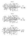
- Figs. 3 and 4 of the drawings The relative directions of component rotation in the three modes described are shown in Figs. 3 and 4 of the drawings.
- Fig. 3 where the input is supplied either by direct rotation of the alpha body 46 at a speed (a) or by the outer shaft 20 driving the sun gear 84 at a speed ⁇ 1, the ring gear 88 will be rotated at a speed lJ2 and in the direction of the arrows shown in Fig. 3.
- the function p may be made to vary between a numerical value of 1.08 and 2.31; that k1 is equal to a -1.6; and k2 is equal to a +.32; and that k3 is equal to -.52.
- a "high" range of forward output speed is achieved by engaging the friction clutch 24 to drive the inner shaft 18 and the alpha body at a speed ( ⁇ ). During this time, the outer shaft 20 will be rotated at speeds faster than the speed of the alpha body to store energy in the flywheel 38. This will have no effect, however, on the hydraulic coupling 32 because of the freewheeling clutch 36 which prevents transmission of torque from the shaft 20 back to the coupling 32.
- Speed ratios in the high range may be varied in accordance with the equation given in Fig. 6. Specifically, by adjusting the rings 60 and 62 in a direction toward the center of the unit 10, the input/output speed ratios may be varied from approximately 3.8:1 to 1.5:1. Quite obviously, by selection of an appropriate final reduction gearing the speed ratio of 1.5:1 may be converted to an overdrive in the context of an automotive drive line.
- the friction clutch 24 is disengaged, the alpha body grounding clutch 94 is engaged and the direction of the output will be reversed as aforementioned in a speed ratio range equal to k3. Which because the sun gear is of smaller diameter than the ring gear 88 will be less than 1 or a speed reduction.
- Energy stored in the flywheel 38 may be transmitted back to the engine crank shaft by engaging the friction clutch 24 or may be transmitted to the power output 12 through the transmission unit in the mode of operation illustrated in Fig. 5. Also, it will be noted that the wide range of continuously variable speed ratios provided by this mode of operation will acommodate relatively high speed rotation of the flywheel. Because the sun gear is in engagement at all times with the planet gear and thus included at all times in the drive line to the output gear 12 transmission of kinetic energy from the flywheel to the output is a function solely of the position of the rings 60 and 62.
Landscapes
- Engineering & Computer Science (AREA)
- General Engineering & Computer Science (AREA)
- Mechanical Engineering (AREA)
- Transmission Devices (AREA)
Claims (10)
Applications Claiming Priority (1)
| Application Number | Priority Date | Filing Date | Title |
|---|---|---|---|
| PCT/US1980/000584 WO1981003370A1 (en) | 1980-05-19 | 1980-05-19 | Power drive line having a wide range of speed ratios |
Publications (3)
| Publication Number | Publication Date |
|---|---|
| EP0052100A1 EP0052100A1 (de) | 1982-05-26 |
| EP0052100A4 EP0052100A4 (de) | 1982-10-07 |
| EP0052100B1 true EP0052100B1 (de) | 1984-09-05 |
Family
ID=22154353
Family Applications (1)
| Application Number | Title | Priority Date | Filing Date |
|---|---|---|---|
| EP81900230A Expired EP0052100B1 (de) | 1980-05-19 | 1980-05-19 | Kraftantriebsreihe mit grossem übersetzungsverhältnisbereich |
Country Status (7)
| Country | Link |
|---|---|
| US (1) | US4495829A (de) |
| EP (1) | EP0052100B1 (de) |
| JP (1) | JPS57500890A (de) |
| CA (1) | CA1156498A (de) |
| DE (1) | DE3050384A1 (de) |
| GB (1) | GB2087008B (de) |
| WO (1) | WO1981003370A1 (de) |
Families Citing this family (9)
| Publication number | Priority date | Publication date | Assignee | Title |
|---|---|---|---|---|
| US4572015A (en) * | 1984-04-04 | 1986-02-25 | Caterpillar Tractor Co. | Nutating traction drive transmission |
| US4882948A (en) * | 1987-06-08 | 1989-11-28 | Byrnes Jr Raymond A | Speed control assembly for nutating cone transmission |
| US4949822A (en) * | 1989-07-20 | 1990-08-21 | Ford Motor Company | Torque converter assembly with reverse acting bypass clutch |
| US6001042A (en) * | 1998-02-05 | 1999-12-14 | Raney; Richard C. | Continuously variable transmission with ratio synchronizing system |
| US7367358B2 (en) * | 2005-02-02 | 2008-05-06 | Universal Infusion Technology, Llc | Medical fluid delivery system and method relating to the same |
| JP2007226175A (ja) * | 2006-01-26 | 2007-09-06 | Epson Imaging Devices Corp | 液晶装置及び電子機器 |
| PL2307762T3 (pl) * | 2008-06-05 | 2016-12-30 | Przekładnia zmienna odwracalna-RVT | |
| EP2554421A3 (de) | 2011-08-01 | 2015-10-07 | Dana Limited | Verfahren und Vorrichtung zur Übertragung von Drehmoment zwischen einem Schwungrad und einem Fahrzeug |
| GB201223469D0 (en) | 2012-12-27 | 2013-02-13 | Mazaro Nv | Design features to improve power density and efficiency of a reversible variable transmission - RVT |
Family Cites Families (32)
| Publication number | Priority date | Publication date | Assignee | Title |
|---|---|---|---|---|
| US30981A (en) * | 1860-12-18 | Improvement in cotton-seed planters | ||
| US2240148A (en) * | 1935-11-29 | 1941-04-29 | Falk Corp | Variable speed transmission |
| US2239983A (en) * | 1936-02-27 | 1941-04-29 | Falk Corp | Variable speed transmission |
| US2062901A (en) * | 1936-04-15 | 1936-12-01 | Louis A Graham | Variable speed transmission |
| US2243224A (en) * | 1936-09-11 | 1941-05-27 | Falk Corp | Variable speed transmission |
| DE706329C (de) * | 1939-03-22 | 1941-05-23 | Herbert Hilkert | Einstellvorrichtung fuer Rundfunkgeraete |
| US2580392A (en) * | 1948-11-13 | 1952-01-01 | Falk Corp | Variable-speed transmission |
| US2755683A (en) * | 1951-09-26 | 1956-07-24 | William J Ryan | Automatic power transmission |
| US2775683A (en) * | 1954-07-16 | 1956-12-25 | Dole Refrigerating Co | Heat exchangers for vaporizing liquid refrigerant |
| US2883883A (en) * | 1957-11-13 | 1959-04-28 | Curtiss Wright Corp | Variable speed transmission |
| US3084569A (en) * | 1961-07-24 | 1963-04-09 | Gen Motors Corp | Multiple speed split torque transmission |
| US3299744A (en) * | 1963-09-04 | 1967-01-24 | Excelermatic | Toroidal-type transmission |
| US3420122A (en) * | 1965-11-11 | 1969-01-07 | Kenzo Okabe | Infinitely variable friction drive |
| US3410146A (en) * | 1966-06-20 | 1968-11-12 | Gen Motors Corp | Roller friction transmission |
| US3628398A (en) * | 1967-08-22 | 1971-12-21 | Walter V Chery | Power transmission |
| US3670595A (en) * | 1969-12-17 | 1972-06-20 | Walter Valdemar Chery | Variable speed automatic transmission |
| US3618423A (en) * | 1970-06-08 | 1971-11-09 | Walter V Chery | Transmission |
| US3688594A (en) * | 1970-11-13 | 1972-09-05 | Bernhard Weber | Infinitely variable transmission |
| US3677109A (en) * | 1971-01-14 | 1972-07-18 | Gates Rubber Co | Continuously variable friction gear |
| DE2347661A1 (de) * | 1972-09-22 | 1974-04-18 | Nissan Motor | Hybrides antriebssystem |
| US4152946A (en) * | 1975-07-22 | 1979-05-08 | Vadetec Corporation | Transmission devices |
| US4112780A (en) * | 1977-04-01 | 1978-09-12 | Vadetec Corporation | Variable speed transmission device |
| US4112779A (en) * | 1976-11-03 | 1978-09-12 | Vadetec Corporation | Variable speed transmission device |
| US4131171A (en) * | 1977-04-11 | 1978-12-26 | Keyes John H | Low energy consumption vehicle propelled by thermal engine |
| US4238976A (en) * | 1978-10-19 | 1980-12-16 | Vadetec Corporation | Infinitely variable power transmission and system |
| SE437867B (sv) * | 1978-10-27 | 1985-03-18 | Caterpillar Tractor Co | Steglost variabel transmissionsenhet |
| US4277982A (en) * | 1979-09-21 | 1981-07-14 | Vadetec Corporation | Torque transmitting body for traction drive transmissions and normal friction force developing method |
| US4233851A (en) * | 1979-05-04 | 1980-11-18 | Vadetec Corporation | Infinitely variable transmission unit and method |
| US4258581A (en) * | 1979-09-21 | 1981-03-31 | Vadetec Corporation | Counterbalancing system for nutational traction drive transmissions |
| US4233859A (en) * | 1979-10-01 | 1980-11-18 | Vadetec Corporation | Infinitely variable transmission unit and system incorporating same |
| US4378708A (en) * | 1980-12-18 | 1983-04-05 | Vadetec Corporation | Normal friction force developing system for traction drive transmissions |
| US4369667A (en) * | 1981-07-10 | 1983-01-25 | Vadetec Corporation | Traction surface cooling method and apparatus |
-
1980
- 1980-05-19 US US06/335,510 patent/US4495829A/en not_active Expired - Fee Related
- 1980-05-19 GB GB8138445A patent/GB2087008B/en not_active Expired
- 1980-05-19 WO PCT/US1980/000584 patent/WO1981003370A1/en active IP Right Grant
- 1980-05-19 JP JP56500441A patent/JPS57500890A/ja active Pending
- 1980-05-19 EP EP81900230A patent/EP0052100B1/de not_active Expired
- 1980-05-19 DE DE803050384T patent/DE3050384A1/de not_active Withdrawn
-
1981
- 1981-05-15 CA CA000377705A patent/CA1156498A/en not_active Expired
Also Published As
| Publication number | Publication date |
|---|---|
| JPS57500890A (de) | 1982-05-20 |
| DE3050384A1 (de) | 1982-06-16 |
| EP0052100A1 (de) | 1982-05-26 |
| US4495829A (en) | 1985-01-29 |
| CA1156498A (en) | 1983-11-08 |
| GB2087008A (en) | 1982-05-19 |
| GB2087008B (en) | 1984-04-18 |
| WO1981003370A1 (en) | 1981-11-26 |
| EP0052100A4 (de) | 1982-10-07 |
Similar Documents
| Publication | Publication Date | Title |
|---|---|---|
| US4856371A (en) | Traction drive transmission system | |
| EP0078124B1 (de) | Kraftfahrzeuggetriebe | |
| US4446756A (en) | Power divider gearbox with a planetary differential gear drive | |
| US5730676A (en) | Three-mode, input-split hybrid transmission | |
| US4334440A (en) | Automatic transmission | |
| EP0322574B1 (de) | Stufenloses Getriebe mit Wirkungsweise zur Drehmomentenregenerierung | |
| GB2031822A (en) | A method and apparatus for driving a load, such as a vehicle | |
| US3503278A (en) | Vehicle drive and steer system with power boost | |
| US3982448A (en) | Input-split hydromechanical transmission | |
| US5024633A (en) | Hydromechanical transmission with adjunct flywheel | |
| EP0052100B1 (de) | Kraftantriebsreihe mit grossem übersetzungsverhältnisbereich | |
| JPH03539B2 (de) | ||
| EP0003397A1 (de) | Mehrgängiges Umlaufräder- Wechselgetriebe | |
| US4238976A (en) | Infinitely variable power transmission and system | |
| US3851544A (en) | Transmission with torque converter and hydrostatic drives | |
| US4116089A (en) | Hydromechanical transmission | |
| US4233859A (en) | Infinitely variable transmission unit and system incorporating same | |
| CA1148770A (en) | Power drive line having a wide range of speed ratios | |
| AU537134B2 (en) | Power drive line having a wide range of speed ratios | |
| US3763718A (en) | Hydromechanical transmission | |
| US4800779A (en) | Hydraulic transmissions | |
| US3587345A (en) | Transmission | |
| US3461743A (en) | Methods and apparatus for reversing the direction of rotation of engine output shafts | |
| CA1178091A (en) | Continuously variable transmission unit | |
| EP0225376B1 (de) | Radial orientierte nutations-antriebsübertragung mit grossem verhältnis an geschwindigkeiten |
Legal Events
| Date | Code | Title | Description |
|---|---|---|---|
| PUAI | Public reference made under article 153(3) epc to a published international application that has entered the european phase |
Free format text: ORIGINAL CODE: 0009012 |
|
| AK | Designated contracting states |
Kind code of ref document: A1 Designated state(s): FR |
|
| 17P | Request for examination filed |
Effective date: 19820428 |
|
| RAP1 | Party data changed (applicant data changed or rights of an application transferred) |
Owner name: IPANEMA COMPANY |
|
| GRAA | (expected) grant |
Free format text: ORIGINAL CODE: 0009210 |
|
| AK | Designated contracting states |
Kind code of ref document: B1 Designated state(s): FR |
|
| ET | Fr: translation filed | ||
| PLBE | No opposition filed within time limit |
Free format text: ORIGINAL CODE: 0009261 |
|
| STAA | Information on the status of an ep patent application or granted ep patent |
Free format text: STATUS: NO OPPOSITION FILED WITHIN TIME LIMIT |
|
| 26N | No opposition filed | ||
| PG25 | Lapsed in a contracting state [announced via postgrant information from national office to epo] |
Ref country code: FR Free format text: LAPSE BECAUSE OF NON-PAYMENT OF DUE FEES Effective date: 19870130 |
|
| REG | Reference to a national code |
Ref country code: FR Ref legal event code: ST |