EP0051698A1 - Paper coating method and apparatus - Google Patents
Paper coating method and apparatus Download PDFInfo
- Publication number
- EP0051698A1 EP0051698A1 EP80303958A EP80303958A EP0051698A1 EP 0051698 A1 EP0051698 A1 EP 0051698A1 EP 80303958 A EP80303958 A EP 80303958A EP 80303958 A EP80303958 A EP 80303958A EP 0051698 A1 EP0051698 A1 EP 0051698A1
- Authority
- EP
- European Patent Office
- Prior art keywords
- web
- coating liquid
- coating
- blade
- pressure
- Prior art date
- Legal status (The legal status is an assumption and is not a legal conclusion. Google has not performed a legal analysis and makes no representation as to the accuracy of the status listed.)
- Granted
Links
- 238000000576 coating method Methods 0.000 title claims abstract description 182
- 239000011248 coating agent Substances 0.000 claims abstract description 164
- 239000007788 liquid Substances 0.000 claims abstract description 84
- 238000000034 method Methods 0.000 claims abstract description 29
- 238000007789 sealing Methods 0.000 claims description 11
- XLYOFNOQVPJJNP-UHFFFAOYSA-N water Substances O XLYOFNOQVPJJNP-UHFFFAOYSA-N 0.000 claims description 6
- 238000010926 purge Methods 0.000 claims description 3
- 238000009827 uniform distribution Methods 0.000 claims description 3
- 230000001737 promoting effect Effects 0.000 claims 1
- 239000000463 material Substances 0.000 abstract description 48
- 239000002245 particle Substances 0.000 abstract description 2
- 230000008901 benefit Effects 0.000 description 10
- 239000000835 fiber Substances 0.000 description 10
- 238000004140 cleaning Methods 0.000 description 9
- 239000000203 mixture Substances 0.000 description 5
- 239000012530 fluid Substances 0.000 description 4
- 229920002472 Starch Polymers 0.000 description 3
- 238000004458 analytical method Methods 0.000 description 3
- 230000008859 change Effects 0.000 description 3
- 239000008199 coating composition Substances 0.000 description 3
- 238000001035 drying Methods 0.000 description 3
- 230000000694 effects Effects 0.000 description 3
- 238000012423 maintenance Methods 0.000 description 3
- 239000000049 pigment Substances 0.000 description 3
- 239000007787 solid Substances 0.000 description 3
- 235000019698 starch Nutrition 0.000 description 3
- 239000008107 starch Substances 0.000 description 3
- 239000004927 clay Substances 0.000 description 2
- 230000000052 comparative effect Effects 0.000 description 2
- 238000010276 construction Methods 0.000 description 2
- 238000011109 contamination Methods 0.000 description 2
- 238000009826 distribution Methods 0.000 description 2
- 230000006872 improvement Effects 0.000 description 2
- 230000007257 malfunction Effects 0.000 description 2
- 238000004519 manufacturing process Methods 0.000 description 2
- 238000005259 measurement Methods 0.000 description 2
- 239000002609 medium Substances 0.000 description 2
- 102000004190 Enzymes Human genes 0.000 description 1
- 108090000790 Enzymes Proteins 0.000 description 1
- 239000004677 Nylon Substances 0.000 description 1
- 239000013543 active substance Substances 0.000 description 1
- 230000002411 adverse Effects 0.000 description 1
- 239000012736 aqueous medium Substances 0.000 description 1
- 239000011230 binding agent Substances 0.000 description 1
- CJZGTCYPCWQAJB-UHFFFAOYSA-L calcium stearate Chemical compound [Ca+2].CCCCCCCCCCCCCCCCCC([O-])=O.CCCCCCCCCCCCCCCCCC([O-])=O CJZGTCYPCWQAJB-UHFFFAOYSA-L 0.000 description 1
- 235000013539 calcium stearate Nutrition 0.000 description 1
- 239000008116 calcium stearate Substances 0.000 description 1
- 239000011247 coating layer Substances 0.000 description 1
- 230000006835 compression Effects 0.000 description 1
- 238000007906 compression Methods 0.000 description 1
- 239000000470 constituent Substances 0.000 description 1
- 230000001276 controlling effect Effects 0.000 description 1
- 238000005520 cutting process Methods 0.000 description 1
- 210000003298 dental enamel Anatomy 0.000 description 1
- 239000000446 fuel Substances 0.000 description 1
- 238000010438 heat treatment Methods 0.000 description 1
- 239000004922 lacquer Substances 0.000 description 1
- 230000013011 mating Effects 0.000 description 1
- 230000007246 mechanism Effects 0.000 description 1
- 238000002156 mixing Methods 0.000 description 1
- 231100000989 no adverse effect Toxicity 0.000 description 1
- 229920001778 nylon Polymers 0.000 description 1
- 230000000704 physical effect Effects 0.000 description 1
- 230000008569 process Effects 0.000 description 1
- 230000001105 regulatory effect Effects 0.000 description 1
- 230000002040 relaxant effect Effects 0.000 description 1
- 238000006748 scratching Methods 0.000 description 1
- 230000002393 scratching effect Effects 0.000 description 1
- 238000003892 spreading Methods 0.000 description 1
- 230000007480 spreading Effects 0.000 description 1
- 229910001220 stainless steel Inorganic materials 0.000 description 1
- 239000010935 stainless steel Substances 0.000 description 1
- 239000013589 supplement Substances 0.000 description 1
Images


Classifications
-
- D—TEXTILES; PAPER
- D21—PAPER-MAKING; PRODUCTION OF CELLULOSE
- D21H—PULP COMPOSITIONS; PREPARATION THEREOF NOT COVERED BY SUBCLASSES D21C OR D21D; IMPREGNATING OR COATING OF PAPER; TREATMENT OF FINISHED PAPER NOT COVERED BY CLASS B31 OR SUBCLASS D21G; PAPER NOT OTHERWISE PROVIDED FOR
- D21H23/00—Processes or apparatus for adding material to the pulp or to the paper
- D21H23/02—Processes or apparatus for adding material to the pulp or to the paper characterised by the manner in which substances are added
- D21H23/22—Addition to the formed paper
- D21H23/32—Addition to the formed paper by contacting paper with an excess of material, e.g. from a reservoir or in a manner necessitating removal of applied excess material from the paper
- D21H23/40—Addition to the formed paper by contacting paper with an excess of material, e.g. from a reservoir or in a manner necessitating removal of applied excess material from the paper only one side of the paper being in contact with the material
-
- B—PERFORMING OPERATIONS; TRANSPORTING
- B05—SPRAYING OR ATOMISING IN GENERAL; APPLYING FLUENT MATERIALS TO SURFACES, IN GENERAL
- B05C—APPARATUS FOR APPLYING FLUENT MATERIALS TO SURFACES, IN GENERAL
- B05C9/00—Apparatus or plant for applying liquid or other fluent material to surfaces by means not covered by any preceding group, or in which the means of applying the liquid or other fluent material is not important
- B05C9/04—Apparatus or plant for applying liquid or other fluent material to surfaces by means not covered by any preceding group, or in which the means of applying the liquid or other fluent material is not important for applying liquid or other fluent material to opposite sides of the work
-
- D—TEXTILES; PAPER
- D21—PAPER-MAKING; PRODUCTION OF CELLULOSE
- D21H—PULP COMPOSITIONS; PREPARATION THEREOF NOT COVERED BY SUBCLASSES D21C OR D21D; IMPREGNATING OR COATING OF PAPER; TREATMENT OF FINISHED PAPER NOT COVERED BY CLASS B31 OR SUBCLASS D21G; PAPER NOT OTHERWISE PROVIDED FOR
- D21H5/00—Special paper or cardboard not otherwise provided for
- D21H5/0005—Processes or apparatus specially adapted for applying liquids or other fluent materials to finished paper or board, e.g. impregnating, coating
- D21H5/0012—Processes or apparatus specially adapted for applying liquids or other fluent materials to finished paper or board, e.g. impregnating, coating by bringing paper into contact with an excess of fluids, the paper carrying away only a part of the fluid material, e.g. by passing through liquids, gases or vapours
- D21H5/0015—Processes or apparatus specially adapted for applying liquids or other fluent materials to finished paper or board, e.g. impregnating, coating by bringing paper into contact with an excess of fluids, the paper carrying away only a part of the fluid material, e.g. by passing through liquids, gases or vapours only one side of the paper being in contact with the treating medium, e.g. paper carried by support
Definitions
- the present invention relates to a method and apparatus for applying a coating material to a web of paper.
- the present invention relates to a coating method, and apparatus of the inverted trail- ing blade type, wherein light, heavy or medium weight coatings may be applied in a novel and improved manner.
- a conventional coater of the trailing blade type includes means for applying, usually unpressurized, coating material to a paper web that ia usually supported and carried by a resilient backing roll, together with a flexible doctor blade: located some distance from and on the trailing side of the-applicator, which serves to level the applied coating.
- a flexible doctor blade located some distance from and on the trailing side of the-applicator, which serves to level the applied coating.
- an excess of coating material is. applied to the web, and the trailing blade then meters or removes. the excess while uniformly spreading the coating onto the web surface..
- the present invention provides a method and apparatus which seek to overcome the abovementioned problems.
- a method of applying coating liquid to a. moving web of paper characterised by the steps of applying coatiag liquid under pressure to one surface of a moving web of paper through an application zone having spaced front and rear edges and laterally spaced side edges, forming and maintaining a reservoir of coating liquid under pressure on the web in the application zone, doctoring the coating liquid on the web at the rear edge of said application zone while the coating liquid ia maintained under pressure, maintaining the coating liquid in the application zone under pressure by substantially sealing the side edges of the zone and by establishing a liquid seal in a gap defined between the web and the front edge of said application zone which extends substantially across the width of the web, and continuously flowing coating liquid under pressure into the application zone to substantially completely and continuously fill said gap with coating liquid for forming said liquid seal, for sealing off the front edge of the application zone and preventing entry of air- and. foreign matter through the gap into the zone, and for continuously purging the coating application zone.
- an apparatus having a limited coating liquid application zone defined by an outlet slot from a chamber, the chamber having front and rear walls and side edges, the side edges being substantially sealed to the web, the front-wall including a front edge spaced from the web and the rear wall carrying a doctor blade engaged with the web, characterized by means for continuously delivering coating liquid under pressure to the chamber,through the outlet slot and into the application zone for application under pressure onto the moving web; means on the front edge of the front wall for forming a narrow gap between said front edge and the moving web of paper for causing the coating liquid under pressure to substantially completely and continuously fill said narrow gap for establishing a liquid seal between the web and said front edge substantially continuously across the web, said liquid seal sealing off the.front edge of the application zone for maintaining the pressure of the coating liquid in said zone and for preventing entry into said zone of air and foreign matter the doctor blade being located immediately to the rear of said liquid' seal for doctoring the coating liquid on the web while the-coating liquid is maintained under pressure, the doctor-blade
- the short dwell time applicator and coating method of the present invention constitute an improvement over- the apparatus and methods of the prior art, in that an enclosed pressure reservoir with a frictionless liquid seal at its forward side is established between the coating applicator, the blade, the supported web and said-seal, which results in pressure application of the coating material to the web to drive the coating into the interstices of the web surface, greater control of coat weights and fewer production problems.
- the applicator generally may be used with a backing roll carrying a web of paper, or a pair of applicators may be arranged on opposite sides of the web so that a web supporting roll is not needed.
- the coating applicator comprises a tapered chamber leading from a supply of coating material to a narrow outlet orifice or slot and a doctor blade extending from the trailing side of the slot in contact with the web.
- leading edge or front side of the chamber adjacent the slot or orifice is closely spaced from the supported web so as to form, in conjunction with the pressurized liquid flowing from the orifice, a liquid seal with the web, and the sides or ends of the orifice are sealed to the backing roll to allow the establishment of the positive liquid pressure of the chamber in the zone of application, with the doctor blade simultaneously levelling the applied coating.
- the coating applicator forms an enclosed pressure chamber with the web to apply a continuous narrow strip or band of pressurized coating material thereto, which enables application of lower coat weights than have heretofore been feasible.
- the maintenance of positive pressure in the zone of application attained by the provision of the trailing blade, the end seals and the leading edge liquid seal, allows for more uniformity and control of application than with prior art methods and permits the use'of both lower and higher viscosity and.lower and higher solids content coating materials than have previously been thought to be feasible.
- the coating method and applicator provide very lightweight coatings, such as 3 grams per square meter per side. It can also apply heavyweight coatings on the order of 22 grams per square meter per side with fewer streaks and scratches than coaters previously used to apply such type coatings.
- a first embodiment of short dwell time applicator 20 of the present invention suitable for practicing the coating method of the present invention is installed on a paper making or coating machine having, a frame 22. and a rotating, resilient backing roll 24 carrying a web 26 of paper moving in the direction indicated by the arrow 27.
- the web 26 wraps around the backing roll 24 for less than 140 degrees,- with the applicator being located near the end or on the last 20 degrees of wrap.
- one or more other coating devices may be located ahead of the applicator on the same backing roll 24.
- One such. device comprises a rotatably mounted dip roll 29, the lower surface of which is disposed in a pan of coating material (not shown) and the upper surface being tangentially in contact with the baoking roll.
- the dip roll 29 may be accompanied by its own doctor blade (not shown).
- the low soak or dwell time of the coating: supplied by the applicator 20 enables the application of a final coating over one or more wet primary coatings without intervening drying. So called "wet-on-wet" methods of coating application are especially advantageous with the present applicator since the final coat may be composed of expensive high-quality materials which may be applied at a very low rate without affecting good web coverage or printing qualities.
- the applicator 20 may be suitably mounted on a pair of pedestals or bases 28 (only one being shown) secured to the frame 22 of the machine.
- Each of the bases 28 comprises a lower portion 30 and an upper portion 32.
- the lower portion 30 is secured to the machine frame 22, as by bolting.
- the lower and upper portions 30 and 32 have co-operating dovetailed, inclined and slidable mating surfaces, 34 and 36, respectively, to permit relative lateral adjustment of the position of the coater applicator 20 for use with various diameter backing rolls 24.
- the angle of in-_ clination of the surfaces 34 and 36 and dimensions and placement of the bases 28 with respect to the rotattng axis of the backing roll are chosen so that the upper portions.32, generally, need only be moved across the inclined surfaces 34 to adjust the position of the applicator 20 for a change in the diameter of the backing roll used without altering the relative angle at which the applicator contacts the backing roll.
- the upper portions 32 on each- side of the backing roll 24 are made to move simultaneously the same distance.
- a screw jack 38 is secured-to each portion 32, the two jacks 38 being connected together by a rotating shaft 42 contained in a tubular housing.
- the screw jacks 38 Upon rotation of the single handle 40, the screw jacks 38 cause two screw shafts 44 to rotate.
- the shafts 44 move in female threads in bodies 46 secured to the lower portions 30.
- rotation of the handle 40 cause both upper portions 32 to move along the inclined surfaces 34 relative to the lower portions 30 to adjust the position of the coating applicator 20 with respect to the axis of the backing roll.
- a second adjustment is provided on the bases 28 to vary the relative angular position of the coating applicator 20 with respect to the backing roll 24.
- large arms 48 are pivotally mounted on a pair of short shafts 50 to the upper portions 32 of the bases.
- the loci of shafts 50 are chosen to coincide generally with the line on which the applicator 20 will contact or be generally tangent to the backing roll 24.
- the lower end of each arm 48 pivotally carries a female threaded portion (not shown) which engages a screw shaft 52.
- the pair of screw shafts 52 extend from a pair of screw jacks 54, which are operated by a common handle 56 and connected together by a rotating shaft 58 in a manner similar to jacks 38.
- the arms 48 can be made to simultaneously pivot an equal angle oramount about the shafts 50.
- pivoting of the arms 48 changes the relative position of the coating applicator 20 with respect to the backing roll 24.
- base locating means 61 are provided on each base 28.
- Each locating means 61 comprises an opening 63 formed on the base parallel to the axis of the backing roll and located concentrically in the shaft 50.
- locating means 61 also includes a locating rod 65 having its outer end slidably mounted in the opening 63.
- the inner end 67 of the rod is ground flat and semi-cylindrical so that the axis of the rod lies on the flat surface. If desired a clamp (not shown) can be provided to hold the rod 65, or the rod can be withdrawn when not needed.
- the rods 65 In setting up apparatus 20, the rods 65 would be installed in the openings 63 and the upper portions 32 of bases 28 moved up or down the inclined surfaces until the flats of the rods 65 are tangent to the outer surface of the particular size backing roll being used. After such position is reached the rods 65 may be removed or clamped in out-of-the-way positions.
- the. upper portions 32 of the bases 28 may be readily positioned with respect to the. lower portions 30 so that the axes of the openings 63, shafts 65 and applicator 20 are generally tangent to the. surface of the selected diameter backing roll-to be used.
- the bases 28 incorporate mechanisms to quickly place in or remove the coating applicator 20 from its operating position abutting the backing roll 25.
- An arm 62 may be connected at one end 64 to the coating apparatus 20, while its other end is connected to a piston rod 66.
- the lower end of the rod 66 co-operates with an air cylinder 68, which in turn is connected to the lower end of the arm 48.
- the coating applicator 20 With-the rod 66 extended from the cylinder 68, the coating applicator 20 is moved toward the backing roll 24 to its operating position, and with the rod 66 retracted into the cylinder 68, the coating applicator 20 is moved away from the backing roll as required for a shutdown or performing maintenance or cleaning.
- Appropriate controls (not shown) are provided for the operator to regulate these movements, and adjustable mechanical stops may be provided to determine the exact location of the operating position with respect to the roll.
- arms 62 previously described nay be replaced by a pair of cleavis brackets 74 (Figure secured to the ends of the applicator 20, the ends of the brackets 74 being connected to the piston rods of the air cylinders 68 for urging the applicator toward and away from the roll.
- the applicator 20 comprises a main support beam 70 of rectangular cross-section, which extends adjacent and coextensively with the backing roll 24.
- the main beam carries either arms 62 or brackets 74.
- a rear wall 76 ( Figure 5) of the coating applicator is secured to the front side of the beam 70 and extends coextensively with and generally parallel to the backing roll.
- a front wall 78 is mounted adjacent to and spaced from the rear wall, the walls being inclined toward one another and together . defining an enclosed chamber 80 converging toward the backing roll.
- One or more inlet-pipes 82 connected to the bottom portion of the rear wall 76 supply the chamber 80 with pressurized liquid coating material from an external header (not shown), the chamber 80 having an open top and being enclosed and sealed at its sides by end places 84 ( Figures 4, 5 and 6), which engage sealing ledges 83 secured to the side of the applicator.
- the front wall 78 is pivotally mounted with respect to the rear wall 76 and is movable away therefrom to enable opening of the chamber 80 for cleaning and also to regulate the width of the metering slot 85 between the upper edges of the walls 76 and 78.
- the front wall 78 is separable from the rear wall 76 and is connected to the ends of downwardly-extending levers 86, the other ends of which are connected to piston rods 87 of power cylinders 88, which in turn are pivotally connected to the beam 70.
- the levers 86 are fulcrumed intermediate their ends on pivots 90 which are also secured to the beam 70.
- Means are provided to fixedly adjust the distance between the. front wall 78 and rear wall 76 and hence to regulate the width of a metering slot 85 and the amount of. coating material passiag. therethrough.
- a series of bolts 94 which pass through the beam.70 in threaded engagement therewith, extend into the chamber 80 and abut. internal webs 96 on the front wall. Adjustment of the bolts 94 to fixed positions held by stop nuts 97 abutting the beam determines the final spacing between the walls 76 and 78 and the width of the metering slot 85 when the chamber 80 is closed.
- the bolts 94 may also be adjusted individually to ensure that the width of the slot 85 is uniform or is of the desired shape along its entire length.
- the coating applicator 20 is positioned closely adjacent the backing roll 24 with the metering slot 85 facing the surface of the paper web 26 on the roll.
- a flexible doctor blade 98 is fixedly clamped to extend from the rear wall 76 into engagement with the web supported on the backing roll, the rear side of the blade being supported by a backing bar 100 secured to the rear wall.
- the blade is held in a slot between a backing member 104 and the rear wall 76 and may be conveniently removed by sliding the blade laterally, parallel to the backing roll, when the chamber 80 is open as shown in Figure 6.
- the blade serves several functions, one of which is to level the coating that is applied to the web.
- the pressure of the blade on the roll is regulated by extension and retraction of the rods 66 of the cylinders 68 connected to arms 62,cr alternatively the cleavis brackets 74, whieh rotate the coating applicator beam 70 about the shafts 60 toward and away from the backing roll 24.
- a liquid seal. is established between the web 26 and the applicator 20, and more particularly an orifice plate 106 thereof.
- the orifice plate 106 is slidably and adjustably mounted on the outside surface of the front wall 78 to be movable toward and away from the backing roll 24.
- the extension of the plate 106 may be fixedly adjusted by a bolt 108 rotatably mounted at one end in a journal 109 extending from the front wall 78, and. the other end being in threaded engagement with the plate.
- The- spacing between the free edge 110 of the plate 106 and the backing roll is very important and should be less than 2.5 cm., (preferably from 0.158 to 1.27 cm.) to. allow the maintenance of the fluid or liquid seal between-the plate and the supported web.
- the trailing blade 98 and forward orifice plate 106 in effect form a portion of an enclosed secondary chamber or reservoir (downstream of the metering slot. 85), the ends of which are enclosed and sealed by flexible triangular shaped end dams 112, which may slightly contact the backing roll surface.
- the end dams 112 are held in compression against the orifice plate 106 by the loaded blade ( Figure 5) and secured by screws 114 ( Figure 4) threadably mounted in brackets 116 secured to both ends of the front wall 78. Loading of the blade 98 against the backing roll 24 causes the blade to deflect inward at its center and increase the seal of the end dams 112.
- liquid coating may be applied across the web in a narrow band or strip under positive pressure.
- the enclosure is completed by the web on the backing roll, the blade 98, the end dams 112 and the liquid seal formed between the orifice plate 106 and the web.
- the spacing is sufficiently narrow to allow the liquid seal of coating material to form between the plate edge 110 and the supported web during operation to prevent loss of pressure so that coating is applied to the web at or near the pressure in the chamber 80.
- This latter pressure can be readily measured by mounting a pressure transducer 117 in the end wall 84 of the chamber 80. The pressure reading of the transducer can then be monitored by the operator and the flow of coating material adjusted to maintain the desired pressure, as will be discussed later.
- the inlet pipes 82 are connected to a source of coating material, which is pumped under pressure into the chamber 80.
- the coating material may comprise any known composition, such as a mixture of fine clay pigment and a binder in an aqueous medium.
- a typical coating-composition may include, for example, a mixture containing 100 parts clay, 16 parts enzyme converted starch and 0.8 parts calcium stearate, said mixture -comprising 50 to 60 percent of an aqueous coating composition.
- the liquid coating material is supplied to the chamber 80 at a rate to maintain it at a pressure from about 17.5 grams per square centimeter or 17.8 cm. of water column to about 350 grams per square centimeter or 380 cm.of water column, and through the metering slot 85, which ensures uniform distribution of the coating to the web. A very slight or small pressure loss occurs in the metering slot 85 so that the coating is applied to the web at substantially the pressure in the chamber 80.
- the liquid seal. between the free edge 110 of the orifice plate 106 and the web surface assists in maintaining such condition. With the arrangement shown, the coating material flows under pressure upward from the chamber 80 and into contact with the web in a narrow band defined by the space between the blade 98 and the liquid seal on the orifice plate 106.
- the gap between the orifice plate and the web surface is very important since it allows a continuous band or - strip of pressurized coating material to be deposited on the web, while at the same time, maintaining the non- abrasive liquid seal with the incoming web.
- the excess coating that flows in a direction opposite the web is allowed to escape through the liquid seal to the exterior of the coating applicator.
- This flow of excess coating serves to maintain a degree of limited circulation in the zone of pressure application, serves to continuously purge the otherwise enclosed system, in the zone of application, strips air from the moving web, and prevents air from entering the applicator where it would prevent the coating contacting the web and would cause streaking or skips.
- the distance between the blade 98 and the orifice plate 106 is defined as the wetted length of web and regulates the width of the band of coating applied to the web and hence the dwell time of the coating on the web between application and wiping.
- the wetted length is adjusted between about 0.635 cm. and 5.715 cm., with about 1.27 to 3.81 cm. being optimum.
- These and other conditions are based on the assumption of a machine web speed in the order of about 6 to 15 metres per second so that the coating material is applied onto the web and doctored within from .0004ths to .0100ths of a second. Where web speed increased, this distance may also be increased so as to maintain adequate dwell time. For example,wher e web speed increased to 24 metre per second, the distance between the liquid seal and doctor-blade may be increased to about 10 to 12..5 cm.
- coating pigment is applied to the web surface in sufficient quantity and under pressure to give a uniform, high-grade coating, but the coating liquid remains in contact with the web only an extremely short time before being doctored so that little liquid penetrates into the web..
- low coat weight papers can be obtained using higher solids content coatings which require less fuel to dry at equivalent coating weights.
- coated paper made according to the method and with the apparatus of the invention generally exhibits less differences between the two coated surfaces of the sheet or web than coated papers produced according to prior art methods.
- coated paper produced in accordance with the invention prints better as it is generally smoother, has greater porosity for the same coat weight, has higher apparent gloss, and tends to have less fiber rise and blistering.
- the paper runs better in printing presses, and in web presses experiences fewer breaks than the aforementioned prior art coated paper.
- Analytical tests made on the paper coated by the apparatus and method of the present invention prove the same superior to paper made on the same papermaking machine, but coated by the well-known standard Beloit flooded hip coater (herein referred to as the "before paper”).
- the "before paper” was generally considered the best coated paper heretofore produced on this papermaking machine.
- the coating for the "before paper” differed very slightly from that for the "after paper”; both wire and felt side coatings for the "before paper” had about 13/100 of starch; whereas the wire and felt side coatings for the "after paper” . had about 15/100 and 14/100 of starch, respectively.
- the papers tested were as follows, with weights expressed in grams per square metre
- M.A.N. Print Tests Another standard test in the printing and papermaking industries, were run for the letter press paper. Here again the tests bore out that the "after paper” had less mottle, and less difference in gloss between the wire and felt sides, than the "before paper". Such desirable lessening of the differences was achieved primarily by increasing the gloss of the felt side, also a desirable plus.
- Sheffield Smoothness Tests a recognized test in the printing and papermaking industries, showed the "after papers” to be superior and smoother than the "before papers". It is well recognized that a smoother paper prints better, especially for a rotogravure process. Test results are as follows, it being noted that the lower the Sheffield Smoothness number, the smoother the paper.
- PSE Paper Surface Efficiency
- a relatively high PSE is desirable, as it reflects a high % K & N and/or B & L Gloss. Also, the differences between the PSE for the wire and felt sides should be minimized.
- the web offset "after paper” exhibited good PSE, but more importantly, the PSE for the wire and felt sides were very similar, indicating that the paper would produce print nearly identically on each of its sides. As for the letter press "after paper”, while the difference between the wire and felt sides was still present, it did exhibit a higher PSE for both sides.
- Fiber rise is a phenomenon caused by moisture in the paper being subject to a rapid change of state from a liquid to a vapour due to sudden heating (as when printed paper is dried in press driers) which forces fibers of the base paper to break through or away from the coating. Fiber rise makes printing difficult, and if severe, can cause an entire printed job to be rejected.
- the paper samples are stored in a controlled environment so that its moisture content is uniform. The sample is then coated with a lacquer to seal in the moisture, and exposed to a preheated radiant heat source to duplicate press drier conditions.
- the sample is then observed and ranked from 0 to 4 against pre-existing standards, 0 reflecting a greater degree of fiber rise while 4 is none. Generally, any sample with a number 2 or below is considered poor.
- the "after paper" had superior resistance to fiber rise in all grades.
- test results above set forth establish, in terms of end results, i.e., the coated paper produced, the superiority of-the coating, method and apparatus of the present invention over one of the better, if not the best, prior art coaters currently in active commercial use for the production of enamel coated printing papers.
- the reverse flow of coating material under pressure through the space between the moving web and the front wall of the coating material chamber or reservoir-, in addition to forming a fluid seal serves as an active agent or vehicle for preventing entry of air into the reservoir and entrainment of air in the coating material being applied to the web, or entrainment of air on the surface of the web between the web and the coating material.
- the reverse flow in effect scours air off the web before the web enters the coater or applicator, whereby the coating is applied to the web in an air-free environment to produce a smooth, uniform, air-free coating on the paper.
- the supply of coating material is essentially self-contained in the coating chamber or reservoir, a break in the web or other malfunction creates only minimal problems in comparison with prior systems, wherein losses of large amounts of coating materials and extensive cleaning operations are to be expected. If a malfunction occurs with the present applicator, the flow of coating material is stopped simply by cutting off the source of pressurized coating. The coating apparatus may then be tilted away from the backing roll and wiped clean, with no concern about clogging of the applicator with hardened coating material, since the supply of coating material is self-contained.
- the interior of the device may be completely exposed for cleaning by first pivoting the coating head away from the backing roll on the shafts 60 and then retracting the rods 87 of cylinders 88 to pivot the front wall 78 away from the rear wall 76, such that the applicator assumes a position shown in Figure 6.
- The-present method and apparatus is particularly suitable for use as the final applicator for so-called "wet-on-wet"-coatings, wherein another coating applicator, such as that indicated at 29 in Figure 1, precedes the applicator 20 without intervening drying. Because of its short dwell or soak time, the present apparatus and method minimizes possible contamination of the first coat by the second coat.
- a distinct and important advantage of the present invention resides in the ability of applying extremely light weight coatings without applying excessive blade pressure to the web.
- coat weight is reduced by increasing blade pressure against the web, with the result that blade wear and the poss- bility of web breakage are increased, thereby necessitating costly and time consuming shutdowns.
- increasing blade pressure past a certain point will not achieve significantly lower coat weights, and a coat weight of less than. about 2.5 pounds per ream per side is impossible or impractical with most conventional equipment such as a dip roll and-inverted blade. This latter method, for example, has been found to require about 1.75 kg. per lineal cm.
- blade pressure to achieve a 4.5 grams per square metre coating per side
- about 1.18 kg. per lineal cm.. of blade pressure is. sufficient for the same weight with the present invention and about 1.32kg. per lineal cm. will achieve a coat weight of about 3 grams per square metre per side.
- blade pressures in excess of 1.62 kg. per lineal cm. are highly impractical and expensive to operate at in terms of wear and shutdowns, and hence this benefit of the present invention becomes readily apparent.
- the use of lower blade pressures are possible as the metering or doctoring of the coating occurs before the coating has had time to significantly dewater on the sheet of the web.
- the above benefits are achieved because a lower soak time forces the coating to remain on the surface, rather than penetrate into the web so that fewer fibers become soaked, thereby resulting in better coverage with less exposed fibers.
- the coated paper produced by the present method is also porous, which is advantageous for printing,. and moreover a dense or nonporous sheet may blister while: being dried.
- the applicator of the present invention though primarily developed to apply lightweight coatings, on the order of 3 grams per square metre (per side) or less, is capable of applying medium and heavyweight coatings, on the order of 22 grams per square metre per side at high speeds, low speeds and intermediate speeds. With this applicator there is little or no tendency to cause scratching, streaking and/or skipping as this applicator can coat paper with lower doctor blade pressure on the web than was possible with previous type coaters, and it doctors high solids content coating before the physical properties of the coating are adversely affected due to dewatering.
- applicator 120 for practicing the method of the present invention. is shown and is generally similar to the applicator 20. Similar elements, parts, or portions of the applicator 120 will be given the same reference numeral as used for the corresponding elements, parts or portions of applicator 20. Applicator 120 has certain features which are improvements over those of applicator 20, and such improved features will now be described in detail.
- the doctor blade 122 is clamped or held in place or position by an air tube 124.
- the use of the air tube 124 to clamp the blade provides the advantage of being able to simply remove or replace the blade 122 by relaxing the air tube, i.e., reducing the pressure therein, and slipping the blade out from either the front (operator) side or back side of the machine.
- the air tube 125 also acts to seal the coating chamber 130, adjacent the end of the blade.
- a second air tube 126 is provided above the air tube 124 and is used to uniformly load the blade toward the backing roll 24 independent of the relative position of the applicator to the backing roll.
- the blade loading resulting from pressurization of the air tube 126 is more uniform along its entire length than it would be if a plurality of mechanical devices, such as screws, spaced along the blade, were used. Further, the exact blade loading condition is easier to duplicate as air pressure is easier to control. Also, the air tube 126 allows the blade 122 to be loaded toward the backing roll without altering the gap between the orifice plate tip 110 and the backing roll 24 so that the fluid seal is maintained.
- the chamber 130 of applicator 120 may be opened for cleaning, as is shown in dashed lines in Figure 7. Prior to being opened, the applicator is moved away from the roll, and it will be understood that the roll 24 shown in dashed lines is included only to illustrate the relative positions of the open coater and the roll, since the roll is not actually moved.
- the chamber 130 of applicator 120 opens only at the top end, and the bottom end of the front wall 132, unlike in applicator 20, remains closed and sealed to the rear wall 134.
- the rear wall 134 is arcuate, as indicated at 136, to accommodate the movement of a seal 138 on the front wall 132.
- the forward wall 132 pivots about a fulcrum 140 on the rear wall.
- the rear wall 134 and front wall 132 forming chamber 130 are angular so that as the coating liquid flows from the lower end of the chamber 130 toward the upper end the liquid tends to be deflected first off the front wall, then off the rear wall and again off the front wall to cause a more uniform mixing and distribution of the coating liquid, this path being indicated by the dotted arrow 142.
- an internal header 144 has been incorporated within the chamber 130 itself.
- a single large diameter pipe 146 supplies the internal header.
- the header 144 itself comprises a rectangular cross-sectional tube 148 of sufficient size to supply the quantity of coating material to the chamber.
- a baffle or false floor 150 is provided in the header to taper or reduce the flow area as the material flows away from the center inlet 146.
- a plurality of equally sized, equally spaced openings 152 are provided along the upper surface of the header, and these openings empty directly into the chamber.
- a flush opening 154 closeable by an appropriate valve is provided at each end of the header so that with the valves open the header can be flushed clean and drained through the center pipe 146, as will be described later.
- Applicator 160 includes a main beam 161 providing the rear wall 161' of the chamber 162' and a forward portion 163 thereof.
- the remaining forward portion of the chamber 162.' is provided by a front wall 164 which seals with other portions of the chamber and is mounted on arms 163' pivoting on brackets 164' carried on the forward portion 163.
- a header such asthe header 144 previously described, is located in the lower end of the chamber.
- the front wall 164 may be pivoted away from the rear wall by a fluid device 165 having a variable volume to be filled with compressed air.
- an improved adjustment is also provided for varying the position of the orifice plate 162.
- the orifice plate 162 is slideably guided for movement in a direction parallel to and on the front wall 164 of the applicator 160, such being accomplished by any one of various conventional means.
- a plurality of operating arms 166 extend from the bottom of brackets 168 secured to the orifice plate.
- the arms 166 each carry a pan bracket 167 for mounting an overflow pan 165 which moves with the orifice plate.
- Each arm 166 at its lower end has in turn a threaded opening 169 receiving the threaded end of a shaft 170 which carries on its other end a pair of cams or rotatable rollers 172 and 173.
- the cams 172 engage in vertical elongated slots 174 formed in a guide bar 176 that is fixed to the front of the wall 164.
- a horizontally extending, orifice adjustment bar 178 is carried and slidably held in a horizontal opening 179 in the guide bar.
- the horizontal-adjustment bar 178 has a plurality of inclined slots 180 which receive the cams 173 of the shafts 170, one such slot 180 being provided for each cam 173.
- the horizontal adjustment bar 178 is secured by a yoke 182 to the movable screw shaft 183 of a screw jack 184 secured to the front wall.
- the adjustment bar 178 moves horizontally and causes the cams 172 and 173, shafts 170 and arms 166 to move in the vertical slots 174 and inclined slots 180, in order to adjust the relative position of the orifice plate 162 with respect to the front wall 164 and to the backing roll.
- the cams 173 are eccentrically mounted on the shafts 170 so that each cam may be set in a position wherein all cams 173 simultaneously engage the upper surface of the inclined slot 180 to provide uniform movement of the plate 162.
- a small pneumatic cylinder 196 is mounted to the applicator 160 directly behind each of the end dams, such dams being constructed of felt or similar material.
- the end of the piston rod of the pneumatic cylinder 196 adjacent the end dam has a tapered or pointed tip 198 which can be forced against the rear of the blade 190 to supplement or increase blade loading at this point and increase the seal of the end dam to the backing roll..
- each end dam holder 200 which is made of nylon, stainless steel or similar material.
- Each end dam holder 200 includes a first outer tubular body 202 and an inner tubular body 203.
- the outer body 202 has a mounting flange 204 extending from its bottom which. can abut a bracket 206 fastened to the applicator to hold the body 202 to the applicator.
- the flange 204 and bracket 206 are held together by a knob 208 which has a threaded portion passing through a threaded opening in the bracket and in clamped engagement with the flange 204.
- the body 203 of the holder are somewhat triangularly shaped in cross-section as shown in Figure 11 to fit in the space between the orifice plate, blade and roll.
- the body 203 has on its inner end a generally triangular, vertical flange member 210 which abuts one end of the dam 192.
- the bodies 202 and 203 have co-axial openings therethrough for receiving a rod element 212.
- the inner end of the rod element 212 has a similar triangularly shaped vertical flange member 214 affixed thereto for abutting the other end of the dam 192.
- the other end of the rod element 212 is threaded and receives a knob or nut 216 for drawing the two triangular shaped flanges 210 and 214 relatively toward each other to compress the flexible dam 192 between them and to cause the adjacent ends of bodies 202 and 203 to abut a second felt or felt- like seal 215 located therebetween.
- the dam 192 is compressed between the triangular shaped flanges 210 and 214 and the felt 215 is compressed between the bodies 202 and 203, the felts tend to expand in directions normal to the pressure to increase the seal between the roll 24, orifice plate 162 and doctor blade 190 to prevent leakage past the felts.
- the sealing provided by dam 192 helps maintain the pressure in the chamber.
- An end dam of this type also has the advantages of requiring a reduced amount of felt, provides a more reliable seal, and readily faclitates blade angle adjustments by merely changing the relative position of the applicator on the backing-roll.
- both sides of the paper web can be coated simultaneously by substituting a second . coater for the backing roll and operating the two coaters in back to back relationship with the web passing between the two.
- the applicators are arranged so that they are generally mirror images of one another, with the web between them so that both sides of the web can be coated simultaneously.
- no backing roll is needed, each of the applicators supporting the web for the other, and permitting the pair of applicators to be located on the coating machine in a location where there is no backing roll.
Abstract
Description
- The present invention relates to a method and apparatus for applying a coating material to a web of paper.
- In particular the present invention relates to a coating method, and apparatus of the inverted trail- ing blade type, wherein light, heavy or medium weight coatings may be applied in a novel and improved manner.
- A conventional coater of the trailing blade type includes means for applying, usually unpressurized, coating material to a paper web that ia usually supported and carried by a resilient backing roll, together with a flexible doctor blade: located some distance from and on the trailing side of the-applicator, which serves to level the applied coating. In general, an excess of coating material is. applied to the web, and the trailing blade then meters or removes. the excess while uniformly spreading the coating onto the web surface..
- In recent years, it has become desirable to produce printing papers having a minimal amount of coating, i..e., in the order of about 3 to 4.5 grams per square meter per side of paper.
- In order to achieve low coat weights. on converitional trailing blade equipment, it is necessary to increase the pressure of the trailing blade against the web, which results in a high rate of wear on the blade and necessitates more frequent replacement of the blade. High blade pressure also increases the possibility of web breakage and streaking caused by foreign particles being caught between the blade and the web.
- - Many conventional coaters inherently employ a relatively long dwell or soak time, which is the time interval between the initial application and final blading of the coating. As a result, the water portion of the coating composition, as well as the water soluble or dispersible materials contained therein migrate into the moving web at a more rapid rate than the pigment and eventually cause an undesirable imbalance in the coating constituents and their rheological properties. Long soak periods are also incompatible with the application of successive wet coats without intervening drying because the successive coats tend to migrate into and contaminate the previous coat.
- The foregoing problems are discussed in U.S.. Patent No. 3,348,526 issued to Neubauer wherein a narrow stream of coating is extruded onto an inverted trailing blade that defines a nip region with the supported web. Since the coating is bladed immediately after application, soak times are purportedly kept to a minimum. However, the coating application is such that the coating material is unpressurized after leaving the orifice. and is supported on the blade or trailing side only, with the leading side of the stream being unsupported and exposed to the environs in the zone of application. Consequently, the coating material is not properly or uniformly applied to the web. Similar disclosures are contained in U.S. Patent No. 3.484,279 (Fig. 3) to Clark et al. and U.S. Patent No. 3,070,066 to Faeber.
- Attempts at pressurized applications of coating material to the web are described in U.S. Patent No. 2,796,846 to Trist and U.S. Patent No. 3,273,535 to Krikorian. In Trist, a second blade is provided at the forward. side of the coating application zone which blade, due to its high friction contact with the web, creates insurmountable obstacles to successful use of the Trist apparatus. In Erikorian, air flow is induced into the coating application zone creating problems of skips and streaks in the applied coating.
- The present invention provides a method and apparatus which seek to overcome the abovementioned problems.
- According to the present invention there is provided a method of applying coating liquid to a. moving web of paper characterised by the steps of applying coatiag liquid under pressure to one surface of a moving web of paper through an application zone having spaced front and rear edges and laterally spaced side edges, forming and maintaining a reservoir of coating liquid under pressure on the web in the application zone, doctoring the coating liquid on the web at the rear edge of said application zone while the coating liquid ia maintained under pressure, maintaining the coating liquid in the application zone under pressure by substantially sealing the side edges of the zone and by establishing a liquid seal in a gap defined between the web and the front edge of said application zone which extends substantially across the width of the web, and continuously flowing coating liquid under pressure into the application zone to substantially completely and continuously fill said gap with coating liquid for forming said liquid seal, for sealing off the front edge of the application zone and preventing entry of air- and. foreign matter through the gap into the zone, and for continuously purging the coating application zone.
- According to a further aspect of the present invention there is provided an apparatus having a limited coating liquid application zone defined by an outlet slot from a chamber, the chamber having front and rear walls and side edges, the side edges being substantially sealed to the web, the front-wall including a front edge spaced from the web and the rear wall carrying a doctor blade engaged with the web, characterized by means for continuously delivering coating liquid under pressure to the chamber,through the outlet slot and into the application zone for application under pressure onto the moving web; means on the front edge of the front wall for forming a narrow gap between said front edge and the moving web of paper for causing the coating liquid under pressure to substantially completely and continuously fill said narrow gap for establishing a liquid seal between the web and said front edge substantially continuously across the web, said liquid seal sealing off the.front edge of the application zone for maintaining the pressure of the coating liquid in said zone and for preventing entry into said zone of air and foreign matter the doctor blade being located immediately to the rear of said liquid' seal for doctoring the coating liquid on the web while the-coating liquid is maintained under pressure, the doctor-blade being spaced from said liquid seal by a small dimension such that the coating liquid is doctored by the blade within about .0004 to about .0100 second of its pressure application to the web.
- The short dwell time applicator and coating method of the present invention constitute an improvement over- the apparatus and methods of the prior art, in that an enclosed pressure reservoir with a frictionless liquid seal at its forward side is established between the coating applicator, the blade, the supported web and said-seal, which results in pressure application of the coating material to the web to drive the coating into the interstices of the web surface, greater control of coat weights and fewer production problems.
- The applicator generally may be used with a backing roll carrying a web of paper, or a pair of applicators may be arranged on opposite sides of the web so that a web supporting roll is not needed. The coating applicator comprises a tapered chamber leading from a supply of coating material to a narrow outlet orifice or slot and a doctor blade extending from the trailing side of the slot in contact with the web. The leading edge or front side of the chamber adjacent the slot or orifice is closely spaced from the supported web so as to form, in conjunction with the pressurized liquid flowing from the orifice, a liquid seal with the web, and the sides or ends of the orifice are sealed to the backing roll to allow the establishment of the positive liquid pressure of the chamber in the zone of application, with the doctor blade simultaneously levelling the applied coating.
- The coating applicator forms an enclosed pressure chamber with the web to apply a continuous narrow strip or band of pressurized coating material thereto, which enables application of lower coat weights than have heretofore been feasible. The maintenance of positive pressure in the zone of application, attained by the provision of the trailing blade, the end seals and the leading edge liquid seal, allows for more uniformity and control of application than with prior art methods and permits the use'of both lower and higher viscosity and.lower and higher solids content coating materials than have previously been thought to be feasible.
- The coating method and applicator provide very lightweight coatings, such as 3 grams per square meter per side. It can also apply heavyweight coatings on the order of 22 grams per square meter per side with fewer streaks and scratches than coaters previously used to apply such type coatings.
- The present invention will now be further described,by way of example, with reference to the accompanying drawings, in which:-
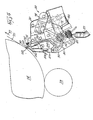
- Figure 1 is a side elevational view of one embodiment of a short dwell time applicator of the present invention installed on a paper coating machine;
- Figure 2 is a partial cross-machine elevational view of the applicator and machine shown in Figure 1;
- Figure 3 is a cross-sectional view taken substantially along the line 3-3 of Figure 1;
- Figure 4 is an. enlarged cross sectional view taken substantially along the line 4-4 of Figure 2;
- Figure 5 is a further enlarged view taken substantially along the line 5-5 of Figure 2 with the applicator in an operating position;
- Figure 6 is a. view similar to Figure 5, but with the applicator open in a cleaning position;
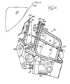
- Figure 7 is a cross sectional view of a second embodiment of short dwell time applicator in an operating position, the applicator being shown in a cleaning position in dotted lines;
- Figure 8 is a cross-sectional view taken substantially along the line 8-8 of Figure 7 showing one half of the applicator's internal header with portions broken away, with other portions of the applicator not being shown;
- Figure 9 is a side elevational view of a third embodiment of short dwell time applicator in an operating position;
- Figure 10 is a partial cross-member view taken substantially along the line 10-10 of Figure 9; and
- Figure 11 is an enlarged view taken substantially along the line 11-11 of Figure 10.
- Referring to Figures 1 and 2, a first embodiment of short
dwell time applicator 20 of the present invention, suitable for practicing the coating method of the present invention is installed on a paper making or coating machine having, aframe 22. and a rotating,resilient backing roll 24 carrying aweb 26 of paper moving in the direction indicated by thearrow 27. Unlike prior devices, theweb 26 wraps around thebacking roll 24 for less than 140 degrees,- with the applicator being located near the end or on the last 20 degrees of wrap. - Due to the compact arrangement of the
applicator 20,. one or more other coating devices may be located ahead of the applicator on thesame backing roll 24. One such. device comprises a rotatably mounteddip roll 29, the lower surface of which is disposed in a pan of coating material (not shown) and the upper surface being tangentially in contact with the baoking roll. Thedip roll 29 may be accompanied by its own doctor blade (not shown). - . The low soak or dwell time of the coating: supplied by the
applicator 20 enables the application of a final coating over one or more wet primary coatings without intervening drying. So called "wet-on-wet" methods of coating application are especially advantageous with the present applicator since the final coat may be composed of expensive high-quality materials which may be applied at a very low rate without affecting good web coverage or printing qualities. - The
applicator 20 may be suitably mounted on a pair of pedestals or bases 28 (only one being shown) secured to theframe 22 of the machine. Each of thebases 28 comprises alower portion 30 and anupper portion 32. Thelower portion 30 is secured to themachine frame 22, as by bolting. The lower andupper portions coater applicator 20 for use with variousdiameter backing rolls 24. The angle of in-_ clination of thesurfaces bases 28 with respect to the rotattng axis of the backing roll are chosen so that the upper portions.32, generally, need only be moved across theinclined surfaces 34 to adjust the position of theapplicator 20 for a change in the diameter of the backing roll used without altering the relative angle at which the applicator contacts the backing roll. - For convenience of making this adjustment and increased accuracy of the same, the
upper portions 32 on each- side of thebacking roll 24 are made to move simultaneously the same distance. To accomplish this result, ascrew jack 38 is secured-to eachportion 32, the twojacks 38 being connected together by a rotatingshaft 42 contained in a tubular housing. Upon rotation of thesingle handle 40, the screw jacks 38 cause twoscrew shafts 44 to rotate. Theshafts 44 move in female threads inbodies 46 secured to thelower portions 30. Thus, rotation of thehandle 40 cause bothupper portions 32 to move along theinclined surfaces 34 relative to thelower portions 30 to adjust the position of thecoating applicator 20 with respect to the axis of the backing roll. - In addition to the adjustment feature discussed above, a second adjustment is provided on the
bases 28 to vary the relative angular position of thecoating applicator 20 with respect to thebacking roll 24. Again referring to Figures 1 and 2,large arms 48 are pivotally mounted on a pair ofshort shafts 50 to theupper portions 32 of the bases. The loci ofshafts 50 are chosen to coincide generally with the line on which theapplicator 20 will contact or be generally tangent to thebacking roll 24. The lower end of eacharm 48, pivotally carries a female threaded portion (not shown) which engages a screw shaft 52. The pair of screw shafts 52 extend from a pair ofscrew jacks 54, which are operated by acommon handle 56 and connected together by a rotatingshaft 58 in a manner similar tojacks 38. Thus, upon rotation of thehandle 56, thearms 48 can be made to simultaneously pivot an equal angle oramount about theshafts 50. As thecoating applicator 20 is pivotally mounted about a pair ofshafts 60 carried intermediate the ends of thearms 48, pivoting of thearms 48 changes the relative position of thecoating applicator 20 with respect to thebacking roll 24. - Referring to Figure 3, to accurately locate the
applicator 20 substantially tangent to the surfaces of the various diameter backing rolls and to reduce the time required in making such adjustment, base locating means 61 are provided on each base 28. Each locating means 61 comprises anopening 63 formed on the base parallel to the axis of the backing roll and located concentrically in theshaft 50. locating means 61 also includes a locatingrod 65 having its outer end slidably mounted in theopening 63. Theinner end 67 of the rod is ground flat and semi-cylindrical so that the axis of the rod lies on the flat surface. If desired a clamp (not shown) can be provided to hold therod 65, or the rod can be withdrawn when not needed. In setting upapparatus 20, therods 65 would be installed in theopenings 63 and theupper portions 32 ofbases 28 moved up or down the inclined surfaces until the flats of therods 65 are tangent to the outer surface of the particular size backing roll being used. After such position is reached therods 65 may be removed or clamped in out-of-the-way positions. Thus, the.upper portions 32 of thebases 28 may be readily positioned with respect to the.lower portions 30 so that the axes of theopenings 63,shafts 65 andapplicator 20 are generally tangent to the. surface of the selected diameter backing roll-to be used. - In addition to the foregoing adjustment, the
bases 28 incorporate mechanisms to quickly place in or remove thecoating applicator 20 from its operating position abutting the backing roll 25. Anarm 62 may be connected at one end 64 to thecoating apparatus 20, while its other end is connected to apiston rod 66. The lower end of therod 66 co-operates with anair cylinder 68, which in turn is connected to the lower end of thearm 48. With-therod 66 extended from thecylinder 68, thecoating applicator 20 is moved toward thebacking roll 24 to its operating position, and with therod 66 retracted into thecylinder 68, thecoating applicator 20 is moved away from the backing roll as required for a shutdown or performing maintenance or cleaning. Appropriate controls (not shown) are provided for the operator to regulate these movements, and adjustable mechanical stops may be provided to determine the exact location of the operating position with respect to the roll. - As an alternative,
arms 62 previously described, nay be replaced by a pair of cleavis brackets 74 (Figure secured to the ends of theapplicator 20, the ends of the brackets 74 being connected to the piston rods of theair cylinders 68 for urging the applicator toward and away from the roll. - As shown in Figures 1, 2,4 and 5, the
applicator 20 comprises amain support beam 70 of rectangular cross-section, which extends adjacent and coextensively with thebacking roll 24. The main beam carries eitherarms 62 or brackets 74. A rear wall 76 (Figure 5) of the coating applicator is secured to the front side of thebeam 70 and extends coextensively with and generally parallel to the backing roll. Afront wall 78 is mounted adjacent to and spaced from the rear wall, the walls being inclined toward one another and together . defining anenclosed chamber 80 converging toward the backing roll. One or more inlet-pipes 82 connected to the bottom portion of therear wall 76 supply thechamber 80 with pressurized liquid coating material from an external header (not shown), thechamber 80 having an open top and being enclosed and sealed at its sides by end places 84 (Figures 4, 5 and 6), which engage sealingledges 83 secured to the side of the applicator. - The
front wall 78 is pivotally mounted with respect to therear wall 76 and is movable away therefrom to enable opening of thechamber 80 for cleaning and also to regulate the width of the metering slot 85 between the upper edges of thewalls front wall 78 is separable from therear wall 76 and is connected to the ends of downwardly-extendinglevers 86, the other ends of which are connected topiston rods 87 ofpower cylinders 88, which in turn are pivotally connected to thebeam 70. Thelevers 86 are fulcrumed intermediate their ends onpivots 90 which are also secured to thebeam 70. Retraction of therods 87 of thecylinders 88 cause thefront wall 78 to pivot away from therear wall 76 to an open position shown in Figure 6, thereby opening up and giving access to the interior of thechamber 80. Extension of therods 87 close the chamber to ready the coater for operation. In the operating position, the lower ends of the front and rear walls abut one another or seal against each other to prevent escape of coating materials, the area of abutment containing a seal 92 (Figures 5 and 6) to prevent loss of pressure during operation of the coater. - Means are provided to fixedly adjust the distance between the.
front wall 78 andrear wall 76 and hence to regulate the width of a metering slot 85 and the amount of. coating material passiag. therethrough. As shown in Figure 5, a series ofbolts 94, which pass through the beam.70 in threaded engagement therewith, extend into thechamber 80 and abut.internal webs 96 on the front wall. Adjustment of thebolts 94 to fixed positions held bystop nuts 97 abutting the beam determines the final spacing between thewalls chamber 80 is closed. Thebolts 94 may also be adjusted individually to ensure that the width of the slot 85 is uniform or is of the desired shape along its entire length. - During operation, the
coating applicator 20 is positioned closely adjacent thebacking roll 24 with the metering slot 85 facing the surface of thepaper web 26 on the roll. Aflexible doctor blade 98 is fixedly clamped to extend from therear wall 76 into engagement with the web supported on the backing roll, the rear side of the blade being supported by abacking bar 100 secured to the rear wall. The blade is held in a slot between a backingmember 104 and therear wall 76 and may be conveniently removed by sliding the blade laterally, parallel to the backing roll, when thechamber 80 is open as shown in Figure 6. As will be hereinafter more fully explained, the blade serves several functions, one of which is to level the coating that is applied to the web. The pressure of the blade on the roll is regulated by extension and retraction of therods 66 of thecylinders 68 connected toarms 62,cr alternatively the cleavis brackets 74, whieh rotate thecoating applicator beam 70 about theshafts 60 toward and away from thebacking roll 24. - In order to close the forward edge of the
chamber 80, a liquid seal. is established between theweb 26 and theapplicator 20, and more particularly anorifice plate 106 thereof. Theorifice plate 106 is slidably and adjustably mounted on the outside surface of thefront wall 78 to be movable toward and away from thebacking roll 24. As shown in Figure 4, the extension of theplate 106 may be fixedly adjusted by a bolt 108 rotatably mounted at one end in a journal 109 extending from thefront wall 78, and. the other end being in threaded engagement with the plate. The- spacing between thefree edge 110 of theplate 106 and the backing roll is very important and should be less than 2.5 cm., (preferably from 0.158 to 1.27 cm.) to. allow the maintenance of the fluid or liquid seal between-the plate and the supported web. - The trailing
blade 98 andforward orifice plate 106 in effect form a portion of an enclosed secondary chamber or reservoir (downstream of the metering slot. 85), the ends of which are enclosed and sealed by flexible triangularshaped end dams 112, which may slightly contact the backing roll surface. Theend dams 112 are held in compression against theorifice plate 106 by the loaded blade (Figure 5) and secured by screws 114 (Figure 4) threadably mounted inbrackets 116 secured to both ends of thefront wall 78. Loading of theblade 98 against thebacking roll 24 causes the blade to deflect inward at its center and increase the seal of theend dams 112. - As the
coating applicator 20 forms an enclosed pressure reservoir with the backing roll, liquid coating may be applied across the web in a narrow band or strip under positive pressure. The enclosure is completed by the web on the backing roll, theblade 98, theend dams 112 and the liquid seal formed between theorifice plate 106 and the web. Although when out of operation there is a slight space between the orifice plate and the backing roll or web, the spacing is sufficiently narrow to allow the liquid seal of coating material to form between theplate edge 110 and the supported web during operation to prevent loss of pressure so that coating is applied to the web at or near the pressure in thechamber 80. One advantage is that this latter pressure can be readily measured by mounting a pressure transducer 117 in theend wall 84 of thechamber 80. The pressure reading of the transducer can then be monitored by the operator and the flow of coating material adjusted to maintain the desired pressure, as will be discussed later. - In operation, the
inlet pipes 82 are connected to a source of coating material, which is pumped under pressure into thechamber 80. The coating material may comprise any known composition, such as a mixture of fine clay pigment and a binder in an aqueous medium. A typical coating-composition may include, for example, a mixture containing 100 parts clay, 16 parts enzyme converted starch and 0.8 parts calcium stearate, said mixture -comprising 50 to 60 percent of an aqueous coating composition. - The liquid coating material is supplied to the
chamber 80 at a rate to maintain it at a pressure from about 17.5 grams per square centimeter or 17.8 cm. of water column to about 350 grams per square centimeter or 380 cm.of water column, and through the metering slot 85, which ensures uniform distribution of the coating to the web. A very slight or small pressure loss occurs in the metering slot 85 so that the coating is applied to the web at substantially the pressure in thechamber 80. The liquid seal. between thefree edge 110 of theorifice plate 106 and the web surface assists in maintaining such condition. With the arrangement shown, the coating material flows under pressure upward from thechamber 80 and into contact with the web in a narrow band defined by the space between theblade 98 and the liquid seal on theorifice plate 106. As mentioned previously, the gap between the orifice plate and the web surface is very important since it allows a continuous band or - strip of pressurized coating material to be deposited on the web, while at the same time, maintaining the non- abrasive liquid seal with the incoming web. The excess coating that flows in a direction opposite the web is allowed to escape through the liquid seal to the exterior of the coating applicator. This flow of excess coating serves to maintain a degree of limited circulation in the zone of pressure application, serves to continuously purge the otherwise enclosed system, in the zone of application, strips air from the moving web, and prevents air from entering the applicator where it would prevent the coating contacting the web and would cause streaking or skips. - The distance between the
blade 98 and theorifice plate 106 is defined as the wetted length of web and regulates the width of the band of coating applied to the web and hence the dwell time of the coating on the web between application and wiping. Preferably, the wetted length is adjusted between about 0.635 cm. and 5.715 cm., with about 1.27 to 3.81 cm. being optimum. These and other conditions are based on the assumption of a machine web speed in the order of about 6 to 15 metres per second so that the coating material is applied onto the web and doctored within from .0004ths to .0100ths of a second. Where web speed increased, this distance may also be increased so as to maintain adequate dwell time. For example,where web speed increased to 24 metre per second, the distance between the liquid seal and doctor-blade may be increased to about 10 to 12..5 cm. - Thus, coating pigment is applied to the web surface in sufficient quantity and under pressure to give a uniform, high-grade coating, but the coating liquid remains in contact with the web only an extremely short time before being doctored so that little liquid penetrates into the web.. As a result, low coat weight papers can be obtained using higher solids content coatings which require less fuel to dry at equivalent coating weights.
- In addition, coated paper made according to the method and with the apparatus of the invention generally exhibits less differences between the two coated surfaces of the sheet or web than coated papers produced according to prior art methods.
- Lessening of the differences between the wire and felt sides is very desirable as it lessens the possibility of one page in a printed publication looking different from the opposite page.
- Further, coated paper produced in accordance with the invention prints better as it is generally smoother, has greater porosity for the same coat weight, has higher apparent gloss, and tends to have less fiber rise and blistering. The paper runs better in printing presses, and in web presses experiences fewer breaks than the aforementioned prior art coated paper.
- Analytical tests made on the paper coated by the apparatus and method of the present invention (herein referred to as the "after paper") prove the same superior to paper made on the same papermaking machine, but coated by the well-known standard Beloit flooded hip coater (herein referred to as the "before paper"). The "before paper" was generally considered the best coated paper heretofore produced on this papermaking machine. In the papers used in the comparative analytical tests, the furnish from which the base papers were made were nearly identical and the coatings very similar in composition. The coating for the "before paper" differed very slightly from that for the "after paper"; both wire and felt side coatings for the "before paper" had about 13/100 of starch; whereas the wire and felt side coatings for the "after paper" . had about 15/100 and 14/100 of starch, respectively. The papers tested were as follows, with weights expressed in grams per square metre
-

- Comparative analyses of the above listed coated papers according to the Erufbau Mopup test, a standard test in the printing and papermaking industries, revealed that the "after papers" exhibited less difference between their wire and felt sides than did the "before papers". Also the "after papers" exhibited less mottle, and/or a finer grain mottle which was less observable.
- A Vandercook Rubber Plate Smoothness Test, another standard test in the printing and papermaking industries,. conformed that the web offset "after paper" exhibited less mottle than the comparable "before paper", and that the same trend, but to a slighter degree, was observed for the letter press "after paper". Again, this test showed smaller differences between the wire and felt sides for the "after papers" than the "before papers". Also, in the "after papers," there was less difference in gloss between the wire and felt sides.
- M.A.N. Print Tests, another standard test in the printing and papermaking industries, were run for the letter press paper. Here again the tests bore out that the "after paper" had less mottle, and less difference in gloss between the wire and felt sides, than the "before paper". Such desirable lessening of the differences was achieved primarily by increasing the gloss of the felt side, also a desirable plus.
- Sheffield Smoothness Tests, a recognized test in the printing and papermaking industries, showed the "after papers" to be superior and smoother than the "before papers". It is well recognized that a smoother paper prints better, especially for a rotogravure process. Test results are as follows, it being noted that the lower the Sheffield Smoothness number, the smoother the paper.

- Also, the well recognized Sheffield Porosity test revealed that the porosity of the web offset "after paper" was increased, which is a desirable feature when the printed paper is dried in the press driers immediately after printing as it permits moisture in the paper to escape without blistering or causing fiber rise. The porosity of the letter-press paper indicated no adverse effect for the "after paper". Test results are as follows, with a higher Sheffield Porosity number indicating increased porosity:

- High Pressure Densometer tests showed that the web offset "after paper" had a substantially lower density, while the letter press "after paper" had a somewhat lower density. These trends are compatible with the changes in porosity and indicative of that factor. with the higher number indicating greater density, the test results are: .

- The standard % K & N Ink Absorbency test showed that the web offset "after paper" had ink absorbency which was much closer-for the two sides, and that the letter press "after paper" had higher ink hold out for the wire side than the comparable "before papers". The higher the % K & N number the greater the tendency for the paper to hold ink out on its surface rather than absorb it. Generally, the higher this tendency the better. Test results are:

- In addition accepted B & L Gloss measurements were made The measurements indicated that the gloss of the "after paper" is more similar for-both the wire and felt sides, which helps minimize a two sided effect., The higher the B & L Gloss number, the glossier the paper.

- While both gloss and ink absorbency are important factors in affecting the appearance or colour of the printed ink on the paper, neither alone is controlling. However, when considered together in an empirical formula well known in the printing and papermaking industries, they can give an accurate prediction. This empirical factor is called the Paper Surface Efficiency ("PSE") and is calculated as follows:

- A relatively high PSE is desirable, as it reflects a high % K & N and/or B & L Gloss. Also, the differences between the PSE for the wire and felt sides should be minimized. The web offset "after paper" exhibited good PSE, but more importantly, the PSE for the wire and felt sides were very similar, indicating that the paper would produce print nearly identically on each of its sides. As for the letter press "after paper", while the difference between the wire and felt sides was still present, it did exhibit a higher PSE for both sides.
-

number 2 or below is considered poor. The "after paper" had superior resistance to fiber rise in all grades.
- The test results above set forth establish, in terms of end results, i.e., the coated paper produced, the superiority of-the coating, method and apparatus of the present invention over one of the better, if not the best, prior art coaters currently in active commercial use for the production of enamel coated printing papers.
- Referring again to the apparatus of the invention, as shown in its preferred embodiment, the reverse flow of coating material under pressure through the space between the moving web and the front wall of the coating material chamber or reservoir-, in addition to forming a fluid seal, serves as an active agent or vehicle for preventing entry of air into the reservoir and entrainment of air in the coating material being applied to the web, or entrainment of air on the surface of the web between the web and the coating material. The reverse flow in effect scours air off the web before the web enters the coater or applicator, whereby the coating is applied to the web in an air-free environment to produce a smooth, uniform, air-free coating on the paper.
- Also, because the supply of coating material is essentially self-contained in the coating chamber or reservoir, a break in the web or other malfunction creates only minimal problems in comparison with prior systems, wherein losses of large amounts of coating materials and extensive cleaning operations are to be expected. If a malfunction occurs with the present applicator, the flow of coating material is stopped simply by cutting off the source of pressurized coating. The coating apparatus may then be tilted away from the backing roll and wiped clean, with no concern about clogging of the applicator with hardened coating material, since the supply of coating material is self-contained.
- Cleaning of-the interior of the chamber is facilitated because of the pivotally mounted
front wall 78. The interior of the device may be completely exposed for cleaning by first pivoting the coating head away from the backing roll on theshafts 60 and then retracting therods 87 ofcylinders 88 to pivot thefront wall 78 away from therear wall 76, such that the applicator assumes a position shown in Figure 6. - The-present method and apparatus is particularly suitable for use as the final applicator for so-called "wet-on-wet"-coatings, wherein another coating applicator, such as that indicated at 29 in Figure 1, precedes the
applicator 20 without intervening drying. Because of its short dwell or soak time, the present apparatus and method minimizes possible contamination of the first coat by the second coat. - A distinct and important advantage of the present invention resides in the ability of applying extremely light weight coatings without applying excessive blade pressure to the web. In most prior art methods, coat weight is reduced by increasing blade pressure against the web, with the result that blade wear and the poss- bility of web breakage are increased, thereby necessitating costly and time consuming shutdowns. In. fact, increasing blade pressure past a certain point will not achieve significantly lower coat weights, and a coat weight of less than. about 2.5 pounds per ream per side is impossible or impractical with most conventional equipment such as a dip roll and-inverted blade. This latter method, for example, has been found to require about 1.75 kg. per lineal cm. of blade pressure to achieve a 4.5 grams per square metre coating per side, whereas about 1.18 kg. per lineal cm.. of blade pressure is. sufficient for the same weight with the present invention and about 1.32kg. per lineal cm. will achieve a coat weight of about 3 grams per square metre per side. It should be understood that blade pressures in excess of 1.62 kg. per lineal cm. are highly impractical and expensive to operate at in terms of wear and shutdowns, and hence this benefit of the present invention becomes readily apparent. The use of lower blade pressures are possible as the metering or doctoring of the coating occurs before the coating has had time to significantly dewater on the sheet of the web. By metering when the coating has not dewatered and the deposited coating layer ismore mobile, there is a reduced tendency for the blade to scratch the web. Also, the absorbency of the paper has less influence on coating pick up than in conventional applicators with long application times.
- The above benefits are achieved because a lower soak time forces the coating to remain on the surface, rather than penetrate into the web so that fewer fibers become soaked, thereby resulting in better coverage with less exposed fibers. The coated paper produced by the present method is also porous, which is advantageous for printing,. and moreover a dense or nonporous sheet may blister while: being dried.
- The applicator of the present invention, though primarily developed to apply lightweight coatings, on the order of 3 grams per square metre (per side) or less, is capable of applying medium and heavyweight coatings, on the order of 22 grams per square metre per side at high speeds, low speeds and intermediate speeds. With this applicator there is little or no tendency to cause scratching, streaking and/or skipping as this applicator can coat paper with lower doctor blade pressure on the web than was possible with previous type coaters, and it doctors high solids content coating before the physical properties of the coating are adversely affected due to dewatering.
- Referring to Figure 7, a second embodiment of
applicator 120 for practicing the method of the present invention. is shown and is generally similar to theapplicator 20. Similar elements, parts, or portions of theapplicator 120 will be given the same reference numeral as used for the corresponding elements, parts or portions ofapplicator 20.Applicator 120 has certain features which are improvements over those ofapplicator 20, and such improved features will now be described in detail. - One change noted is that the
doctor blade 122 is clamped or held in place or position by anair tube 124. The use of theair tube 124 to clamp the blade provides the advantage of being able to simply remove or replace theblade 122 by relaxing the air tube, i.e., reducing the pressure therein, and slipping the blade out from either the front (operator) side or back side of the machine. To assist in locating the blade it can be provided with detents on its lower edge to.locate the blade spacially in the aplicator. The air tube 125 also acts to seal thecoating chamber 130, adjacent the end of the blade. - A
second air tube 126 is provided above theair tube 124 and is used to uniformly load the blade toward thebacking roll 24 independent of the relative position of the applicator to the backing roll. The blade loading resulting from pressurization of theair tube 126 is more uniform along its entire length than it would be if a plurality of mechanical devices, such as screws, spaced along the blade, were used. Further, the exact blade loading condition is easier to duplicate as air pressure is easier to control. Also, theair tube 126 allows theblade 122 to be loaded toward the backing roll without altering the gap between theorifice plate tip 110 and thebacking roll 24 so that the fluid seal is maintained. - Like the
chamber 80 ofapplicator 20, thechamber 130 ofapplicator 120 may be opened for cleaning, as is shown in dashed lines in Figure 7. Prior to being opened, the applicator is moved away from the roll, and it will be understood that theroll 24 shown in dashed lines is included only to illustrate the relative positions of the open coater and the roll, since the roll is not actually moved. Thechamber 130 ofapplicator 120 opens only at the top end, and the bottom end of thefront wall 132, unlike inapplicator 20, remains closed and sealed to the rear wall 134. The rear wall 134 is arcuate, as indicated at 136, to accommodate the movement of aseal 138 on thefront wall 132. Theforward wall 132 pivots about afulcrum 140 on the rear wall. Aside from the advantage of the open chamber forming a trough to contain-the water used to flush thechamber 130 during cleaning, another advantage of this construction is that theseal 138 andarcuate sealing surface 136 on the rear wall are swept clean each time the chamber is opened or closed to minimize possible contamination of the seal or sealing surface. - Rather than being straight, the rear wall 134 and
front wall 132 formingchamber 130 are angular so that as the coating liquid flows from the lower end of thechamber 130 toward the upper end the liquid tends to be deflected first off the front wall, then off the rear wall and again off the front wall to cause a more uniform mixing and distribution of the coating liquid, this path being indicated by the dottedarrow 142. - Referring to Figures 7 and 8, another advantage of
applicator 120 overapplicator 20 is that aninternal header 144 has been incorporated within thechamber 130 itself. Now, instead of having a plurality of pipes (aspipes 82 in applicator 20) to supply coating material to the chamber, a singlelarge diameter pipe 146 supplies the internal header. Theheader 144 itself comprises a rectangular cross-sectional tube 148 of sufficient size to supply the quantity of coating material to the chamber. To assist in uniformly distributing the coating material a baffle orfalse floor 150 is provided in the header to taper or reduce the flow area as the material flows away from thecenter inlet 146. To distribute the coating material to thechamber 130, a plurality of equally sized, equally spacedopenings 152 are provided along the upper surface of the header, and these openings empty directly into the chamber. To assist in clean up, aflush opening 154 closeable by an appropriate valve (not shown) is provided at each end of the header so that with the valves open the header can be flushed clean and drained through thecenter pipe 146, as will be described later. - Referring to Figures 9, 10 and 11, a third embodiment of
applicator 160 of the present invention and for practicing the method of the present invention is shown and is generally similar to theapplicators Applicator 160 includes amain beam 161 providing the rear wall 161' of the chamber 162' and aforward portion 163 thereof. The remaining forward portion of thechamber 162.' is provided by afront wall 164 which seals with other portions of the chamber and is mounted on arms 163' pivoting on brackets 164' carried on theforward portion 163. A header, such astheheader 144 previously described, is located in the lower end of the chamber. Of course, should it be desired, instead of a single header, several similar type headers could be provided, and such promote more even distribution. As in the other embodiments, thefront wall 164 may be pivoted away from the rear wall by afluid device 165 having a variable volume to be filled with compressed air. - An improved adjustment is also provided for varying the position of the
orifice plate 162. As shown in Figure 9, theorifice plate 162 is slideably guided for movement in a direction parallel to and on thefront wall 164 of theapplicator 160, such being accomplished by any one of various conventional means. To cause such movement a plurality of operatingarms 166 extend from the bottom ofbrackets 168 secured to the orifice plate. Thearms 166 each carry apan bracket 167 for mounting anoverflow pan 165 which moves with the orifice plate. Eacharm 166 at its lower end has in turn a threadedopening 169 receiving the threaded end of ashaft 170 which carries on its other end a pair of cams orrotatable rollers 172 and 173. Thecams 172 engage in verticalelongated slots 174 formed in aguide bar 176 that is fixed to the front of thewall 164. A horizontally extending,orifice adjustment bar 178 is carried and slidably held in ahorizontal opening 179 in the guide bar. The horizontal-adjustment bar 178 has a plurality ofinclined slots 180 which receive the cams 173 of theshafts 170, onesuch slot 180 being provided for each cam 173. Thehorizontal adjustment bar 178 is secured by ayoke 182 to the movable screw shaft 183 of ascrew jack 184 secured to the front wall. Thus, as thehandle 186 of the screw jack is rotated, theadjustment bar 178 moves horizontally and causes thecams 172 and 173,shafts 170 andarms 166 to move in thevertical slots 174 andinclined slots 180, in order to adjust the relative position of theorifice plate 162 with respect to thefront wall 164 and to the backing roll. The cams 173 are eccentrically mounted on theshafts 170 so that each cam may be set in a position wherein all cams 173 simultaneously engage the upper surface of theinclined slot 180 to provide uniform movement of theplate 162. - Referring to Figures 9 and 10, in order to increase the loading of the
doctor blade 190 and enddams 192 against the backing roll to eliminate or reduce leakage, a smallpneumatic cylinder 196 is mounted to theapplicator 160 directly behind each of the end dams, such dams being constructed of felt or similar material. The end of the piston rod of thepneumatic cylinder 196 adjacent the end dam has a tapered or pointedtip 198 which can be forced against the rear of theblade 190 to supplement or increase blade loading at this point and increase the seal of the end dam to the backing roll.. Thus it is possible to reduce or eliminate end dam leakage by increasing the pressure provided on the blade at its ends and on the end dams, without having to use a high pressure across the entire blade. Also, such adjustment for providing additional sealing is more duplicative since the air pressure supplied to the cylinders is readily controlled. - Referring to Figures 10 and 11, the
end dams 192 are each carried in anovel holder 200 which is made of nylon, stainless steel or similar material. Eachend dam holder 200 includes a first outertubular body 202 and an innertubular body 203. Theouter body 202 has a mountingflange 204 extending from its bottom which. can abut abracket 206 fastened to the applicator to hold thebody 202 to the applicator. Theflange 204 andbracket 206 are held together by aknob 208 which has a threaded portion passing through a threaded opening in the bracket and in clamped engagement with theflange 204. Thebodies 202 and. 203 of the holder are somewhat triangularly shaped in cross-section as shown in Figure 11 to fit in the space between the orifice plate, blade and roll. Thebody 203 has on its inner end a generally triangular,vertical flange member 210 which abuts one end of thedam 192. Thebodies rod element 212. The inner end of therod element 212 has a similar triangularly shapedvertical flange member 214 affixed thereto for abutting the other end of thedam 192. The other end of therod element 212 is threaded and receives a knob ornut 216 for drawing the two triangular shapedflanges flexible dam 192 between them and to cause the adjacent ends ofbodies like seal 215 located therebetween. As thedam 192 is compressed between the triangular shapedflanges bodies roll 24,orifice plate 162 anddoctor blade 190 to prevent leakage past the felts. The sealing provided bydam 192 helps maintain the pressure in the chamber. An end dam of this type also has the advantages of requiring a reduced amount of felt, provides a more reliable seal, and readily faclitates blade angle adjustments by merely changing the relative position of the applicator on the backing-roll. - Even with the more effective seal provided by the
end dam 192, problems can arise should coating material work its way past this seal and accumulate on the outer ends of the orifice plate or doctor blade. Coating material accumulated in such places could scratch or damage the backing roll. In order to prevent coating material accumulating in such places, large relief openings or cut-away s 220 and 222 are formed or cut in each end of theorifice plate 162 and in eachholder 200, respectively. Thus, should any coating material work its way past the felt seals 192, it flows over the relief cut-aways 222 and 220 in the holder and the orifice plate into theoverflow pan 165 on the front of the applicator. The felt seals 215 direct the flow into the cut-aways and prevent any coating material from passing by and accumulating on the extreme ends of the orifice plate or doctor blade to scratch or otherwise damage the roll. - If desired, both sides of the paper web can be coated simultaneously by substituting a second . coater for the backing roll and operating the two coaters in back to back relationship with the web passing between the two. In this case, the applicators are arranged so that they are generally mirror images of one another, with the web between them so that both sides of the web can be coated simultaneously. Of particular advantage is that no backing roll is needed, each of the applicators supporting the web for the other, and permitting the pair of applicators to be located on the coating machine in a location where there is no backing roll.
- While three embodiments of apparatus of the present invention, for practicing the method of the invention, have been described and illustrated, it is to be understood that the invention is not limited thereto, but comprehends other constructions, arrangements of parts and details and other steps and orders for performing the method, without departing from the scope of the invention as set forth in the appended claims.
Claims (10)
Priority Applications (3)
| Application Number | Priority Date | Filing Date | Title |
|---|---|---|---|
| DE8080303958T DE3071691D1 (en) | 1980-11-06 | 1980-11-06 | Paper coating method and apparatus |
| AT80303958T ATE21222T1 (en) | 1980-11-06 | 1980-11-06 | METHOD AND DEVICE FOR COATING PAPER. |
| EP80303958A EP0051698B2 (en) | 1980-11-06 | 1980-11-06 | Paper coating method and apparatus |
Applications Claiming Priority (1)
| Application Number | Priority Date | Filing Date | Title |
|---|---|---|---|
| EP80303958A EP0051698B2 (en) | 1980-11-06 | 1980-11-06 | Paper coating method and apparatus |
Publications (3)
| Publication Number | Publication Date |
|---|---|
| EP0051698A1 true EP0051698A1 (en) | 1982-05-19 |
| EP0051698B1 EP0051698B1 (en) | 1986-08-06 |
| EP0051698B2 EP0051698B2 (en) | 1994-08-17 |
Family
ID=8187291
Family Applications (1)
| Application Number | Title | Priority Date | Filing Date |
|---|---|---|---|
| EP80303958A Expired - Lifetime EP0051698B2 (en) | 1980-11-06 | 1980-11-06 | Paper coating method and apparatus |
Country Status (3)
| Country | Link |
|---|---|
| EP (1) | EP0051698B2 (en) |
| AT (1) | ATE21222T1 (en) |
| DE (1) | DE3071691D1 (en) |
Cited By (4)
| Publication number | Priority date | Publication date | Assignee | Title |
|---|---|---|---|---|
| US4887547A (en) * | 1985-07-31 | 1989-12-19 | Jagenberg Aktiengesellschaft | Apparatus for continuously applying a uniform coating to a material web |
| EP0787857A1 (en) | 1996-02-03 | 1997-08-06 | Jagenberg Papiertechnik GmbH | Device for coating a moving web, in particular paper or board |
| WO1998050631A1 (en) * | 1997-05-07 | 1998-11-12 | Jagenberg Papiertechnik Gmbh | Device for applying a coating material |
| CN108262219A (en) * | 2018-03-27 | 2018-07-10 | 深圳市世椿智能装备股份有限公司 | A kind of liquid sealed type valve member |
Citations (6)
| Publication number | Priority date | Publication date | Assignee | Title |
|---|---|---|---|---|
| US3273536A (en) * | 1961-06-26 | 1966-09-20 | Time Inc | Trailing-blade coater including fluid seal |
| US3413143A (en) * | 1963-12-10 | 1968-11-26 | Ilford Ltd | High speed coating apparatus |
| GB1266745A (en) * | 1969-06-11 | 1972-03-15 | ||
| US4063531A (en) * | 1976-02-03 | 1977-12-20 | Beloit Corporation | Coater for both sides of traveling web |
| US4102299A (en) * | 1974-10-16 | 1978-07-25 | Inventing S.A. | Apparatus for applying a coating composition onto a moving web |
| US4167914A (en) * | 1977-05-25 | 1979-09-18 | Bolton-Emerson, Inc. | Rotating rod, rotating press roll nip coating apparatus |
-
1980
- 1980-11-06 AT AT80303958T patent/ATE21222T1/en not_active IP Right Cessation
- 1980-11-06 EP EP80303958A patent/EP0051698B2/en not_active Expired - Lifetime
- 1980-11-06 DE DE8080303958T patent/DE3071691D1/en not_active Expired
Patent Citations (6)
| Publication number | Priority date | Publication date | Assignee | Title |
|---|---|---|---|---|
| US3273536A (en) * | 1961-06-26 | 1966-09-20 | Time Inc | Trailing-blade coater including fluid seal |
| US3413143A (en) * | 1963-12-10 | 1968-11-26 | Ilford Ltd | High speed coating apparatus |
| GB1266745A (en) * | 1969-06-11 | 1972-03-15 | ||
| US4102299A (en) * | 1974-10-16 | 1978-07-25 | Inventing S.A. | Apparatus for applying a coating composition onto a moving web |
| US4063531A (en) * | 1976-02-03 | 1977-12-20 | Beloit Corporation | Coater for both sides of traveling web |
| US4167914A (en) * | 1977-05-25 | 1979-09-18 | Bolton-Emerson, Inc. | Rotating rod, rotating press roll nip coating apparatus |
Cited By (6)
| Publication number | Priority date | Publication date | Assignee | Title |
|---|---|---|---|---|
| US4887547A (en) * | 1985-07-31 | 1989-12-19 | Jagenberg Aktiengesellschaft | Apparatus for continuously applying a uniform coating to a material web |
| EP0787857A1 (en) | 1996-02-03 | 1997-08-06 | Jagenberg Papiertechnik GmbH | Device for coating a moving web, in particular paper or board |
| US6066208A (en) * | 1996-02-03 | 2000-05-23 | Jagenberg Papiertechnik Gmbh | Apparatus for coating a continuously moving web |
| WO1998050631A1 (en) * | 1997-05-07 | 1998-11-12 | Jagenberg Papiertechnik Gmbh | Device for applying a coating material |
| CN108262219A (en) * | 2018-03-27 | 2018-07-10 | 深圳市世椿智能装备股份有限公司 | A kind of liquid sealed type valve member |
| CN108262219B (en) * | 2018-03-27 | 2023-04-28 | 深圳市世椿智能装备股份有限公司 | Liquid sealing type valve assembly |
Also Published As
| Publication number | Publication date |
|---|---|
| EP0051698B1 (en) | 1986-08-06 |
| ATE21222T1 (en) | 1986-08-15 |
| EP0051698B2 (en) | 1994-08-17 |
| DE3071691D1 (en) | 1986-09-11 |
Similar Documents
| Publication | Publication Date | Title |
|---|---|---|
| US4250211A (en) | Paper coating method and apparatus | |
| US4512279A (en) | Paper coating apparatus | |
| EP0496946B1 (en) | Method of and apparatus for coating high speed traveling webs | |
| US4440105A (en) | Paper coating apparatus having a replaceable orifice plate | |
| EP0454643B1 (en) | Coating device for coating of a size-press roll, paper or board | |
| CA1061200A (en) | Coater for both sides of traveling web | |
| US3179536A (en) | Method and apparatus for coating paper | |
| US4440809A (en) | Method and apparatus for recirculating coating liquid in a paper coating apparatus | |
| US5882406A (en) | Film applicator with adjustable dynamic extraction flow regulator | |
| EP0596365B1 (en) | Method and apparatus for two-side coating of a thin printing paper web | |
| FI97817C (en) | Method and arrangement for coating a moving track | |
| EP0675984B1 (en) | Apparatus and method of minimizing skip coating on a paper web | |
| EP0935696A1 (en) | Method and arrangement for coating a moving paperboard web | |
| CA2227501C (en) | Rod holder with separate positionable contact elements for rod metering | |
| US5647909A (en) | Apparatus for applying coating to paper web including successive doctoring steps | |
| EP0051698B1 (en) | Paper coating method and apparatus | |
| NO177236B (en) | Method and apparatus for coating paper | |
| CN1617965A (en) | Method and apparatus for making a multilayer coating | |
| US4981726A (en) | Method and apparatus for dispensing coating materials on a moving substrate with a smoothing member and supporting structure | |
| US5674551A (en) | Method and apparatus for coating a moving paper web | |
| US6099909A (en) | Method and device for coating a size-press roll, paper, or board | |
| CA2120999C (en) | Method and assembly for loading a doctor blade | |
| US5516365A (en) | Apparatus for coating a paper or cardboard web | |
| CA1125587A (en) | Paper coating method and apparatus | |
| CA2107277C (en) | Method and apparatus for two-side coating of a thin printing paper web made of mechanical pulp |
Legal Events
| Date | Code | Title | Description |
|---|---|---|---|
| PUAI | Public reference made under article 153(3) epc to a published international application that has entered the european phase |
Free format text: ORIGINAL CODE: 0009012 |
|
| AK | Designated contracting states |
Designated state(s): AT BE CH DE FR GB IT LU NL SE |
|
| 17P | Request for examination filed |
Effective date: 19821004 |
|
| ITF | It: translation for a ep patent filed |
Owner name: BARZANO' E ZANARDO ROMA S.P.A. |
|
| GRAA | (expected) grant |
Free format text: ORIGINAL CODE: 0009210 |
|
| AK | Designated contracting states |
Kind code of ref document: B1 Designated state(s): AT BE CH DE FR GB IT LI LU NL SE |
|
| REF | Corresponds to: |
Ref document number: 21222 Country of ref document: AT Date of ref document: 19860815 Kind code of ref document: T |
|
| REF | Corresponds to: |
Ref document number: 3071691 Country of ref document: DE Date of ref document: 19860911 |
|
| PG25 | Lapsed in a contracting state [announced via postgrant information from national office to epo] |
Ref country code: LU Free format text: LAPSE BECAUSE OF NON-PAYMENT OF DUE FEES Effective date: 19861130 |
|
| ET | Fr: translation filed | ||
| PLBI | Opposition filed |
Free format text: ORIGINAL CODE: 0009260 |
|
| 26 | Opposition filed |
Opponent name: VALMET PAPER MACHINERY INC. Effective date: 19870506 Opponent name: JAGENBERG AG Effective date: 19870506 |
|
| NLR1 | Nl: opposition has been filed with the epo |
Opponent name: VALMET PAPER MACHINERY INC. Opponent name: JAGENBERG AG |
|
| ITTA | It: last paid annual fee | ||
| PUAA | Information related to the publication of a b2 document modified |
Free format text: ORIGINAL CODE: 0009299PMAP |
|
| PUAH | Patent maintained in amended form |
Free format text: ORIGINAL CODE: 0009272 |
|
| STAA | Information on the status of an ep patent application or granted ep patent |
Free format text: STATUS: PATENT MAINTAINED AS AMENDED |
|
| 27A | Patent maintained in amended form |
Effective date: 19940817 |
|
| AK | Designated contracting states |
Kind code of ref document: B2 Designated state(s): SE |
|
| ITF | It: translation for a ep patent filed |
Owner name: BARZANO' E ZANARDO ROMA S.P.A. |
|
| REG | Reference to a national code |
Ref country code: CH Ref legal event code: AEN |
|
| R27A | Patent maintained in amended form (corrected) |
Effective date: 19940817 |
|
| NLR2 | Nl: decision of opposition | ||
| PGFP | Annual fee paid to national office [announced via postgrant information from national office to epo] |
Ref country code: BE Payment date: 19941104 Year of fee payment: 15 |
|
| ET3 | Fr: translation filed ** decision concerning opposition | ||
| PGFP | Annual fee paid to national office [announced via postgrant information from national office to epo] |
Ref country code: NL Payment date: 19941130 Year of fee payment: 15 |
|
| NLR3 | Nl: receipt of modified translations in the netherlands language after an opposition procedure | ||
| PGFP | Annual fee paid to national office [announced via postgrant information from national office to epo] |
Ref country code: CH Payment date: 19950120 Year of fee payment: 15 |
|
| EAL | Se: european patent in force in sweden |
Ref document number: 80303958.5 |
|
| PG25 | Lapsed in a contracting state [announced via postgrant information from national office to epo] |
Ref country code: LI Effective date: 19951130 Ref country code: CH Effective date: 19951130 Ref country code: BE Effective date: 19951130 |
|
| BERE | Be: lapsed |
Owner name: CONSOLIDATED PAPERS INC. Effective date: 19951130 |
|
| PG25 | Lapsed in a contracting state [announced via postgrant information from national office to epo] |
Ref country code: NL Effective date: 19960601 |
|
| REG | Reference to a national code |
Ref country code: CH Ref legal event code: PL |
|
| NLV4 | Nl: lapsed or anulled due to non-payment of the annual fee |
Effective date: 19960601 |
|
| APAC | Appeal dossier modified |
Free format text: ORIGINAL CODE: EPIDOS NOAPO |
|
| APAC | Appeal dossier modified |
Free format text: ORIGINAL CODE: EPIDOS NOAPO |
|
| PGFP | Annual fee paid to national office [announced via postgrant information from national office to epo] |
Ref country code: GB Payment date: 19991020 Year of fee payment: 20 |
|
| PGFP | Annual fee paid to national office [announced via postgrant information from national office to epo] |
Ref country code: FR Payment date: 19991117 Year of fee payment: 20 |
|
| PGFP | Annual fee paid to national office [announced via postgrant information from national office to epo] |
Ref country code: AT Payment date: 19991119 Year of fee payment: 20 |
|
| PGFP | Annual fee paid to national office [announced via postgrant information from national office to epo] |
Ref country code: SE Payment date: 19991123 Year of fee payment: 20 |
|
| PGFP | Annual fee paid to national office [announced via postgrant information from national office to epo] |
Ref country code: DE Payment date: 19991130 Year of fee payment: 20 |
|
| PG25 | Lapsed in a contracting state [announced via postgrant information from national office to epo] |
Ref country code: GB Free format text: LAPSE BECAUSE OF EXPIRATION OF PROTECTION Effective date: 20001105 |
|
| PG25 | Lapsed in a contracting state [announced via postgrant information from national office to epo] |
Ref country code: AT Free format text: LAPSE BECAUSE OF EXPIRATION OF PROTECTION Effective date: 20001106 |
|
| PG25 | Lapsed in a contracting state [announced via postgrant information from national office to epo] |
Ref country code: SE Free format text: THE PATENT HAS BEEN ANNULLED BY A DECISION OF A NATIONAL AUTHORITY Effective date: 20001129 |
|
| REG | Reference to a national code |
Ref country code: GB Ref legal event code: PE20 Effective date: 20001105 |
|
| EUG | Se: european patent has lapsed |
Ref document number: 80303958.5 |
|
| APAH | Appeal reference modified |
Free format text: ORIGINAL CODE: EPIDOSCREFNO |