EP0051349A1 - A lead - acid battery construction - Google Patents
A lead - acid battery construction Download PDFInfo
- Publication number
- EP0051349A1 EP0051349A1 EP81303302A EP81303302A EP0051349A1 EP 0051349 A1 EP0051349 A1 EP 0051349A1 EP 81303302 A EP81303302 A EP 81303302A EP 81303302 A EP81303302 A EP 81303302A EP 0051349 A1 EP0051349 A1 EP 0051349A1
- Authority
- EP
- European Patent Office
- Prior art keywords
- battery
- lead
- electrodes
- reactive
- electrode means
- Prior art date
- Legal status (The legal status is an assumption and is not a legal conclusion. Google has not performed a legal analysis and makes no representation as to the accuracy of the status listed.)
- Granted
Links
Images


Classifications
-
- H—ELECTRICITY
- H01—ELECTRIC ELEMENTS
- H01M—PROCESSES OR MEANS, e.g. BATTERIES, FOR THE DIRECT CONVERSION OF CHEMICAL ENERGY INTO ELECTRICAL ENERGY
- H01M4/00—Electrodes
- H01M4/02—Electrodes composed of, or comprising, active material
- H01M4/14—Electrodes for lead-acid accumulators
-
- H—ELECTRICITY
- H01—ELECTRIC ELEMENTS
- H01M—PROCESSES OR MEANS, e.g. BATTERIES, FOR THE DIRECT CONVERSION OF CHEMICAL ENERGY INTO ELECTRICAL ENERGY
- H01M10/00—Secondary cells; Manufacture thereof
- H01M10/06—Lead-acid accumulators
- H01M10/12—Construction or manufacture
- H01M10/125—Cells or batteries with wound or folded electrodes
-
- Y—GENERAL TAGGING OF NEW TECHNOLOGICAL DEVELOPMENTS; GENERAL TAGGING OF CROSS-SECTIONAL TECHNOLOGIES SPANNING OVER SEVERAL SECTIONS OF THE IPC; TECHNICAL SUBJECTS COVERED BY FORMER USPC CROSS-REFERENCE ART COLLECTIONS [XRACs] AND DIGESTS
- Y02—TECHNOLOGIES OR APPLICATIONS FOR MITIGATION OR ADAPTATION AGAINST CLIMATE CHANGE
- Y02E—REDUCTION OF GREENHOUSE GAS [GHG] EMISSIONS, RELATED TO ENERGY GENERATION, TRANSMISSION OR DISTRIBUTION
- Y02E60/00—Enabling technologies; Technologies with a potential or indirect contribution to GHG emissions mitigation
- Y02E60/10—Energy storage using batteries
-
- Y—GENERAL TAGGING OF NEW TECHNOLOGICAL DEVELOPMENTS; GENERAL TAGGING OF CROSS-SECTIONAL TECHNOLOGIES SPANNING OVER SEVERAL SECTIONS OF THE IPC; TECHNICAL SUBJECTS COVERED BY FORMER USPC CROSS-REFERENCE ART COLLECTIONS [XRACs] AND DIGESTS
- Y02—TECHNOLOGIES OR APPLICATIONS FOR MITIGATION OR ADAPTATION AGAINST CLIMATE CHANGE
- Y02P—CLIMATE CHANGE MITIGATION TECHNOLOGIES IN THE PRODUCTION OR PROCESSING OF GOODS
- Y02P70/00—Climate change mitigation technologies in the production process for final industrial or consumer products
- Y02P70/50—Manufacturing or production processes characterised by the final manufactured product
Definitions
- the invention relates to a lead-acid battery construction including positive electrode means and negative electrode means supported in contact with separator means in which is contained an electrolyte.
- grid structure which may be of varying forms.
- One form may consist of a lead top bar, a terminal and depending spines.
- Other forms of grid structures may comprise, for example, lead frames including a terminal, expanded or perforated lead sheet including a terminal, etc.
- the invention as claimed is intended to satisfy these needs by providing a.lead-acid battery construction of a unique nature characterized by reactively retarded electrode means, and which has greatly increased power-to-weight and power-to-volume ratios in a degree significantly greater than is presently known to those skilled in the art.
- a battery according to the invention is capable of faster discharging and recharging and also capable of deep cycling over long periods of time in a manner not heretofore realized.
- Another object of the invention is to provide a sealed lead acid battery including positive and negative electrodes and separator means containing electrolyte, in which the separator means is less than fully saturated with the electrolyte, thus allowing oxygen to pass easily between positive and negative electrodes but in which a surfeit of electrolyte is available to the electrodes.
- This reactively retarded electrode concept has originated from a recognition of the fact that lead may occur in a reactive form, i.e. sponge lead, and also in a non-reactive form, i.e. solid lead; and secondly from a conceptual realization that Pb0 2 , when suitably utilized, may present reacting portions and non-reacting portions of Pb0 2 which may exist in very desirable forms in a common electrolyte environment with reactive ardnon-reactive forms of lead.
- positive and negative electrodes comprise thin foil bodies: (6) surface areas of the said electrodes, with respect of thickness of these electrodes, may be substantially greater than those of conventional electrodes thus allowing for faster discharge and recharge; and (7) virtually any foraminous separator means of conventional construction combined with such electrodes may be sufficiently thick so as to provide an excess of electrolyte to the electrodes without the separator means in itself being fully saturated with the said electrolyte.
- the reactive lead of the negative electrode means may occur in a mass capable of defining and controlling the mass of the reacting Pb0 2 of the positive electrode means within limits set to enable the reactive lead of the negative electrode means and reacting Pb0 2 portions of the positive electrode means, in suitable electrolyte means, to generate an electrical current of a magnitude which can be cooperatively carried by the non-reactive lead of the negative electrode means and the non-reacting PbO 2 of the positive electrode means.
- Figure 1 illustrates a gridless battery 2 of the invention and of a non- cylindrical form. Positive and negative terminals 4 and 6 are shown connected by conductors 8 and 10, respectively, to a simulated operating load 12 of an appreciable nature.
- This gridless battery includes positive electrode.means having reacting and non-reacting PbO 2 portions and negative electrode means having reactive and non-reactive lead portions. It will also be understood that battery 2 may be illustrative of a battery made up of a plurality of current generating cells which may be designed for meeting a range of desired requirements.
- test cell such as that illustrated in Figures 2 and 3, as well as the test cell illustrated on a larger scale in Figure 6; may provide a means by which these'inventive aspects may be most readily perceived.
- the simple test cell 14 shown in Figures 2 and 3 is 'illustrated on a larger scale in Figure 6 and is characterized by a construction in which there are employed electrodes in the form of thin foil.
- a thin foil element 16 constitutes a positive electrode for the test cell and thin foil bodies 18 and 20 are arranged to constitute negative electrodes. These foil components are also shown in more detail in Figure 4.
- separator means 22 Located between the electrodes in abutting relationship therewith is separator means 22, most clearly shown in Figure 4.
- separator means As is customary in making battery separator means there is utilized a foraminous material which is substantially chemically inert in a sulfuric acid environment. Examples of suitable separator materials include glass wool, needle punched polyester, and the like.
- the separator means 22 is folded about positive electrode foil component 16 which projects upwardly beyond the upper end of separator means 22, as is shown in more detail in Figure 4.
- FIG. 3 shows that the lower end of the separator means 22 extends beyond the lower end of foil component 16.
- Components 18 and 20 are also arranged in abutting relationship with outer sides of separator means 22 such that the lower ends of components 18 and 20 project considerably beyond the lower end of separator means 22 and such that the upper end of separator means 22 extends beyond upper ends of components 18 and 20. With such an arrangement adjacent foil surfaces are always isolated from one another by some portion of separator means 22.
- the foils of Figures 2 and 3 may be combined with substrates to form laminated bodies 32, as is illustrated, for example, in Figure 5.
- a thin substrate 34 of a plastic material which is substantially chemically inert in a sulfuric acid environment and which is located between layers 36 and 38 of lead.
- the substrate may comprise a plastic material such as polyester, polypropylene, etc., and the outer lead layers may be applied to the substrate by various processes such as vacuum deposition, rolling, electrodeless plating, adhesive means, and the like.
- the assembly of electrodes 16, 18 and 20 and separator means 22, is combined with wall portions 24 and 26, and is held together by holding tapes 28 and 30.
- separator means 22 may have a thickness of 0.4 mm and, in combination with a separator of this thickness, there may be employed laminated foil components 32.
- laminated foil components 32 In this laminated foil arrangement there are employed outer lead layers 36 and 38 of a thickness of 25 microns in combination with a substrate 34 having a thickness of 25 microns. It will be understood that other dimensional relationships may be employed in accordance with particular battery requirements.
- Such components when assembled as described, constitute a test cell 14 which is ready to receive a "formation electrolyte" such as a relatively low specific gravity sulfuric acid. Addition of the electrolyte may be readily accomplished by immersing the cell body in a sulfuric acid bath until the separator means becomes partially saturated, e.g. 80% saturated.
- a final step in the preparation of test cell 14, is a controlled processing operation which enables cell 14 to generate an electrical current. This is achieved by subjecting the cell to a limited electrochemical forming process of the Plante formation class wherein electrochemical forming is controlled in a manner so as to provide a cell characterized by reactively retarded electrode portions.
- These electrode portions are of a predetermined nature as earlier specified, and include negative electrodes having reactive and non-reactive lead portions and a positive electrode having reacting and non-reacting portions of Pb0 2 ..
- test cell 14A As an aid to more readily visualizing these chemical changes and the limited extent to which they take place in accordance with the invention, another test cell 14A is illustrated in Figure 6.
- electrochemically formed electrodes As shown on a greatly enlarged scale in which dimensional relationships may be more readily perceived.
- the cell 14A includes a positive electrode 37, electrochemically formed negative electrodes 39 and 40 and separator means 42, which are assembled between wall portions 44 and 46.
- the negative electrodes include plastic substrates 48 and 50 wherein the electrochemical formation has been controlled so as to produce layers 52 and 54 of non-reactive lead, i.e. solid lead, and layers 56 and 58 of reactive lead, i.e. sponge lead.
- Figure 6 illustrates a positive electrode 37, in place of electrode 16 of Figures 2 and 3, which includes a plastic substrate 60 wherein electrochemical formation has been controlled to produce, at either side of the substrate, outer layers of Pb0 2 .
- the layers of PbO 2 comprise both reacting Pb0 2 , 66, and non-reacting Pb0 2 , 64.
- the relative thickness of the two portions 64 and 66 of the Pb0 2 layers are controlled by the amount of reactive lead 56 and 58 present in the negative electrodes denoted by arrows 39 and 40 ' respectively. It will be observed that an upper portion of the positive electrode 37 has not undergone electrochemical change, and therefore layers as 62 of lead will remain at this upper portion of electrode 37.
- Controlled Plante formation of cell 14A to provide the reactively retarded electrodes disclosed, as noted above, involves specific processing steps which are hereinafter disclosed in detail. However, assuming that cell 14A is in a suitably formed state, a consideration of the invention method of operating the reactively retarded electrodes is desirable since control of chemical reactions during operation is closely related to control of chemical reactions of Plante formation.
- the specific gravity of the formation electrolyte is raised to an operating level (e.g. 1.320 specific gravity). Any "formation additives" present are allowed to remain in the battery.
- the electrolyte gravity may be raised by suitable means, e.g. by adding a predetermined quantity of very - high gravity acid (for example, 1.450 specific gravity acid) such that the resultant mixture will be of the desired specific gravity, or by removing the formation electrolyte by a vacuum process and then introducing an operating electrolyte of the desired specific gravity by a similar vacuum process.
- FIG 7 there is indicated diagrammatically a battery similar to cell 14A in which battery components. are shown separately in a composite block diagram representing a battery at rest (i.e. neither undergoing charging nor discharging).
- the elements include: (1) a negative electrode comprising reactive and non-reactive lead portions;, (2) separator means containing electrolyte; and (3) a positive electrode comprising reacting and non-reacting portions of Pb0 2 .
- Figure 8 is a diagrammatic representation of the component parts of Figure 7 connected to a typical electrical load.
- electrical current indicated by the directional arrow
- the reactive lead of the negative electrode and the reacting Pb0 2 portion of the positive electrode become gradually electrochemically transformed into PbS0 4 (as indicated by curved dashed lines) by the reactions known to the art as the "double sulfate" reactions.
- These reactions and their associated resultant transformations of the reactants take place and continue to take place as long as the load is connected to the battery and until the reactive lead portion of the negative electrode has been completely transformed into PbS0 4 .
- That portion of the PbO 2 of the positive electrode which becomes transformed into PbS0 4 during the aforementioned reaction is called “reacting PbO 2 ". That portion of the Pb0 2 of the positive electrode remaining after the reactions have ceased is called “non-reacting Pb0 2 , since this portion of the Pb0 2 does not undergo electrochemical reaction.
- the positive electrode is of gridless construction, i.e. there is no specially fabricated current carrying lead structure such as a typical grid fabricated with a lead frame and various cross members present in this electrode, the non-reacting Pb0 2 portion of this electrode must be of a mass sufficient to carry all of the current required by the load and generated by the battery.
- the negative electrode is of gridless construction as well, although its non-reactive lead portion may be regarded as behaving somewhat similarly to a grid. This non-reactive lead portion of the negative electrode must also be of a mass sufficient to carry all of the current as noted above.
- the total amount of PbO 2 in the positive electrode including both reacting ardnon-reacting PbO 2 must be of a mass such that, once the double sulfate reactions cease, the remaining portion of the said Pb0 2 in the positive electrode (this portion being referred to as "non-reacting") is sufficient to carry the required current for the load disclosed above.
- FIG 9 is a diagrammatic representative of the component parts of the battery of Figure 8 starting in a discharged condition and connected to a power supply for recharging.
- charging current provided by the power supply as indicated by the directional arrow, flows through the battery the PbS0 4 of the positive and negative electrodes gradually becomes electrochemically transformed back into reacting Pb0 2 and reactive lead, respectively.
- These electrochemical transformations also result from the well known double sulfate reactions.
- reactively retarded electrodes of the class disclosed are subjected to a controlled electrochemical formation of Pb0 2 from lead in sulfuric acid in which is contained an anion-providing formation additive (e.g.KC10 4 ) which will produce a soluble lead salt.
- an anion-providing formation additive e.g.KC10 4
- KC10 4 anion-providing formation additive
- That electrode which is ultimately to be a negative electrode is first partially formed into a positive electrode and, when a predetermined portion of the lead of this electrode (this portion to correspond with the aforementioned "reactive lead") has been transformed into Pb0 2 , reversing the formation current and continuing formation until all of the Pb0 2 present in the final negative electrode has been transformed into reactive lead and until at least a corresponding amount of the lead present in the final positive electrode has been transformed into Pb0 2 . It is this selectively controlled formation process which provides the reactively retarded electrodes characteristic of the invention.
- Figures 10-13 illustrate diagrammatically the steps of this Plante formation in situ.
- Figure 10 illustrates portions of component parts of a battery of the invention, prior to formation.
- diagrammatically substantially identical positive and negative electrodes comprising metallic lead on a suitable substrate, combined with separator means, said separator means having "formation electrolyte" contained therein.
- FIG 11 is a diagrammatic representation of a first phase of the particular Plante formation process of the invention.
- a power supply is connected to the battery in reversed polarity; that is, the positive output terminal of the power supply is connected to the negative terminal of the battery, etc.
- Electrical current as indicated by the directional arrow, is caused to flow.
- the lead of the positive electrode will be unaltered in this step, while the lead of the negative electrode will be gradually electrochemically transformed into Pb0 2 , as is indicated by the curved dashed lines. It is pointed out that there may be a brief transitory phase to this transformation (not shown in Figure 11) wherein a portion of the leading edge of the Pb0 2 -lead transition stage becomes PbS0 4 but this has no significance in the process.
- the electrical current of this part of the formation process is to be discontinued when that (predetermined) portion of the lead of the negative electrode, which in its ultimate form is to be reactive or "sponge" lead, has been transformed into Pb0 2 .
- This cessation of current flow constitutes an important part of the process, since continued application of electrical current beyond the point indicated would result in a transformation to PbO 2 of that lead portion which is required to be non-reactive, and the relationship between the reactive and non-reactive portions of the negative electrode serves to provide the reactively retarded characteristic to the battery during discharge.
- FIG. 12 A second phase of the formation process is illustrated diagrammatically in Figure 12.
- a power supply is shown connected with conventional polarity (e.g. positive to positive), to the battery components of Figure" 11.
- conventional polarity e.g. positive to positive
- the Pb0 2 of the negative electrode becomes gradually electrochemically transformed into PbS0 4 , as indicated by curved dashed lines at the left hand side of Figure 12.
- the metallic lead of the positive electrode is gradually transformed into Pb0 2 , again with there occurring a brief transitory PbS0 4 stage at the leading edge of the Pb-Pb0 2 transition phase (shown in this Figure and in Figure 13).
- the particular form of PbO 2 resulting from this phase of formation may be ⁇ -PbO 2 , a form which is somewhat less porous than "normal", or ⁇ -PbO 2 .
- the electrical current flow may be terminated, provided that a quantity of Pb0 2 in the positive electrode at least equivalent to the reactive lead of the negative electrode has been produced.
- Some metallic lead may remain in the positive electrode. However, since this metallic lead, during normal recharging, will ultimately become PbO 2 , this remaining lead must be of a mass sufficient to carry required current through the positive electrode after it has been completely transformed into P b0 2 .
- the electrical current flow will not be terminated as suggested above, but will be allowed to continue until all of the lead of the positive electrode has become transformed into a-Pb0 2 .
- a-Pb0 2 is formed by positively charging PbS0 4 in the presence of a low specific gravity acid
- ⁇ -PbO 2 is formed by positively charging PbSO 4 in the presence of a higher specific gravity acid. Therefore, during normal operation, that portion of the a-Pb0 2 which becomes transformed into PbS0 4 during discharge will, upon recharge, be transformed into ⁇ -PbO 2 . That a-Pb0 2 which has not been discharged due to the reactive retardation characteristic of the invention may remain a-Pb0 2 .
- the varying depth of the ⁇ -PbO 2 portion is indicated by the curved dashed lines in Figure 14.
- Electrodes are fabricated from a laminated foil material such as that denoted by the arrow 32 in Figure 5.
- Central core layer of substrate 34 of a suitable plastic material such as polyethylene or polypropylene, is 25 microns thick; outer lead layers 36 and 38 are also 25 microns thick.
- the total weight of this laminated foil will be 6.5 g/100 cm 2 of area, of which 5.5 g/100 cm 2 represents lead.
- Thetheoretical capacity of an electrode fabricated from such a material is 1.42 ampere-hours/100 cm 2 at the 10-hour rate.
- the utilization of the reactive lead active material in a negative electrode at this rate will only be 70% and, further, it is desired to limit the depth of discharge of the battery of the invention to 56% in order to provide a long life. Therefore, the negative electrodes should be formed to some percentage "x" of their theoretical capacity such that: or
- the thickness of the negative electrodes After formation to 0.8 ampere-hours/100 cm 2 , the thickness of the negative electrodes will be 110 microns.
- Characteristics of an electrode group comprising one positive electrode 100 cm 2 in area, one negative electrode 100 cm 2 in area, and two separators containing electrolyte will be as follows:
- test cell As a more specific example of a "test cell, having specific parameters, a cell similar to that denoted by arrow 14 in Figures 2 and 3 is constructed having electrodes fabricated from laminated foils as specified above. Positive electrode 16 and negative electrodes 18 and 20 are initially identical in composition, and are 1 cm wide. Their length is chosen such that, when they are combined with a 0.4 mm thick separator means 22 as shown in Figure 4, those portions of their length which are adjacent to one another are 10 mm long, resulting in an active surface area of 10 cm 2 .
- separator means 22 may be partially saturated with a formation electrolyte comprising H 2 S0 4 of 1.10 specific gravity, to which (8g KClO 4 )/(liter of H 2 S0 4 ) has been added. Since the area of the electrodes is 10 cm 2 (per side) the expected capacity will be (0.80 amp-hrs) (10 cm 2 ) or 0.08 ampere-hours. Negative 10 0 cm 2 electrodes are to be formed to this value which, it will be recalled, corresponds to 80% formation and 70% utilizat-' tion of negative active material. Theoretical capacity of the electrodes is 0.142 ampere hours; thus an 80% formation will require approximately 0.12 ampere-hours of formation current.
- the cell is connected to a power supply in the reversed polarity configuration as illustrated diagrammatically in Figure 11, and is charged with the negative electrodes connected as positive electrodes at 10 milliamperes for a period of 12 hours.
- the power supply is connected conventionally as indicated diagrammatically in Figures 12-13 and charged at 10 milliamperes for 24 hours such that substantially all of the lead of the positive electrode becomes transformed into Pb0 2 .
- the electrolyte gravity has been adjusted to an operating specific gravity of 1.320, a capacity of 0.081 ampere-hours at the 10-hour rate is realized.
- separator means 22 being 0.4mm thick, is capable of absorbing an amount of operating electrolyte substantially in excess of that required by the electrodes while being no more than 80% saturated with the said electrolyte. Therefore, in order to provide a path for oxygen transport from the positive electrodes to the negative electrode during charging, separator means 22 will be no more than 80% saturated with the operating electrolyte.
- an additional calculation may be set forth showing the voltage drop caused by the utilization of Pb0 2 as the current carrier in the positive electrode.
- the cell may be assumed to have a capacity of 0.05 ampere-hours.
- the non-reacting PbO 2 portion (worst case, i.e. end of discharge) will have a resistance of 0.4 ohms.
- the Pb0 2 of the positive electrode may comprise either ⁇ -PbO 2 , more porous ⁇ -PbO 2 , or a combination thereof. It is commonly assumed that the more porous material ( ⁇ -PbO 2 ) will have a lower conductivity than the less porous ⁇ -PbO 2 . It is known to the battery art, however, that ⁇ -PbO 2 , when maintained in a relatively confined state, will have a conductivity at least equivalent to that of ⁇ -PbO 2 ; thus either form of Pb0 2 will be operable.
- composite lead foils of the invention may be produced by various means, and that negative electrodes may be separately formed using dummy positive electrodes. It is hereby also disclosed that positive electrodes may be directly produced by deposition or application of Pb0 2 layers of sufficient thickness directly upon a suitable substrate.
- mine lamp battery 68 is illustrated in Figure 15.
- Battery 68 comprises two cells, 70 and 72, in a common jar 74 of a suitable material, for example polycarbonate, internally divided by a partition 76 and having a bottom cap portion 78 and top cell cover portion 80.
- Bottom cap portion 78 and a top cell portion 80 may be affixed to jar 74 by means of solvent cementing, ultrasonic welding, or other means.
- top cell cover portion 80 Extending through holes in top cell cover portion 80 are positive and negative terminal posts 82 and 84, respectively, which may be used to connect battery 68 to a suitable load or to charging means. Terminal posts 82 and 84 may be sealed to cell cover portion 80 by any conventional means, for instance epoxy resin 86. In addition, each cell may be provided with a sealable filling port as 100 at top and bottom thereof.
- positive and negative electrodes 88 of foil construction, as well as separator means and electrolyte.
- the positive electrodes may be connected electrically to one another and to positive port 82 by suitable means such as, for example, a lead bridge 90.
- Negative electrodes may be connected together by similar means.
- Figure 16 illustrates a cross-section of an upper portion of one cell of a similar battery, in which a plurality of positive electrodes 92, negative electrodes 94 and electrolyte-bearing separator means 96 are provided in a j ar 98.
- Positive and negative electrodes 92 and 94 may be fabricated from a lamination similar to that shown in Figure 5.
- Figure 16 shows, for example, a plurality of positive electrodes each having a substrate 102 and two outer layers of metallic lead 104.
- a lead bridge 106 Interconnecting the positive electrodes 92 is a lead bridge 106, for example, cast or soft welded to upper ends of the positive electrodes 92, such that upper ends of their outer lead layers 104 become integrated with the lead mass of the bridge 106.
- a terminal post 108 Protruding from an upper side of lead bridge 106 is a terminal post 108, which extends through cell cover 110. Sealing between post 108 and cell cover 110 may be accomplished in a conventional manner, such as by the use of epoxy resin 112.
- FIG 17 illustrates, in an inverted position, a lower portion of the battery 68 of Figure 15, partially broken away.
- battery 68 comprises two cells 70 and 72 in a common jar 74, the cells being separated from one another by internal partition 76.
- Each cell includes a plurality of positive and negative electrodes of foil construction, as well as separator means.
- cell 72 of Figure 17 is illustrated a plurality of negative electrodes 114, interconnected to one another by a lead bridge 116 which may be affixed to these electrodes in the manner disclosed with respect to Figure 16.
- a terminal post 118 Protruding from one side of bridge 116 is a terminal post 118, which extends through bottom wall 120 of jar 74, and which is sealed to bottom wall 120 in a conventional manner.
- Shown in cell 70 is one negative electrode 122 and one part 124 of separator means. Also shown is a plurality of positive electrodes 126, which may be interconnected to one another by means of a lead bridge 128, having a terminal post 130, in the manner previously disclosed.
- Each cell includes an electrode group internally disposed therein and comprising a plurality of positive electrodes, negative electrodes and separator means interleaved with one another and positive and negative interconnecting lead bridges with their associated terminal posts. All of such electrode groups are identical in composition to one another, although adjacent cells will contain electrode groups which are in an inverted position with respect to one another. In this manner cell interconnections may be simplified.
- Figure 17 shows that the negative terminal post 118. of cell 72 and the positive terminal post 130 of cell 70 lie adjacent to one another, and may be connected to one another by means of a lead connecting link 132, which may be fused to the said terminal posts in a conventional manner.
- lead connecting link 132 which may be fused to the said terminal posts in a conventional manner.
- those cells which are to be electrically connected to one another in series should be located adjacent to one another and should have their internal electrode groups inverted with respect to one another. Connecting links in this series configuration will alternate between upper and lower parts of the battery.
- Each cell may also include sealable filling ports as 100', Figure 17, at its bottom portion, as previously disclosed.
- Sealable filling ports 100, 100' referred to above may be utilized in one desirable mode for introducing formation electrolyte into the. cells, removal of the formation electrolyte after formation has been carried out and for introducing operating electrolyte into the cells.
- ports as 100 and 100' may be sealed. These ports, in sealed state, may be designed to function as "blow off valves to relieve extreme internal gas overpressures.
- a typical battery for mine lamp use similar to battery 68 of Figure 15 may include for example two cells, each containing 34 positive electrodes, each electrode having an active surface area of 5.7 cm x 16.4 cm equalling 93.48 cm 2 , fabricated from foils as specified above. Also included may be 35 negative electrodes having a similar active surface area, and interleaved separator means. The total positive surface area will be 34 x 93.48 which equals 3.78 cm 2 . Since the electrode group will have a capacity of 0.8 ampere-hour per 100 cm 2 of positive surface area at the 10-hour rate, the expected capacity will be.
- the total weight of the electrode groups for the two cells, including electrolyte, will be approximately 1.6 kilograms.
- the above battery is designed to have the same dimensions, and thus the same volume, as a conventional mine lamp battery. This leads to some important comparisons whereby conventional ratio values are taken with reference to an index of 1.0:
- the battery of the invention clearly meets the stated objectives of increasing power-to-weight and power-to-volume ratios.
- one important object of this invention is to develop a battery construction which will resist "zreeing".
- This "treeing" phenomenon is one of the primary causes of failure in conventional lead-acid batteries which are deeply cycled, and results from the fact that the electrolyte in a deeply discharged battery may suffer from an extreme depletion of sulfate ions available for reaction.
- the potential for treeing may be significantly reduced or eliminated in any conventional battery by: (1) providing an excess of available sulfate ions in the electrolyte, for example, by the addition of a salt such as MgS0 4 ; (2) by limiting the depth of discharge such that there are always sufficient sulfate ions available in the electrolyte; or (3) by a combination of (1) and (2) above. In this manner the formation of soluble lead hydrates may be precluded, and treeing substantially eliminated.
- a salt such as MgS0 4 may, of course, be added to the electrolyte of a battery of the invention.
- the second procedure noted above is an inherent feature of a properly-designed battery of the invention in that, as previously disclosed, the depth of discharge is limited by the amount of reactive lead provided in the reactively retarded negative electrode.
- the amount of sulfuric acid (H 2 SO 4 ) electrolyte absorbed in the separator means is significantly greater than that amount required to discharge the battery to this limit, and thus no soluble lead hydrates can be formed.
- one object of this invention is to make a sealed lead-acid battery.
- the "oxygen cycle" of gas recombination in such batteries, wherein oxygen evolved at the positive electrodes during charging becomes recombined with hydrogen at the negative electrodes to form water, is well-known to the art.
- Conditions prerequisite to such recombination include (1) a large surface area for the negative electrodes, and (2) a relatively easy path of travel for the oxygen between the positive and negative electrodes.
- Also desirable may be some overpressure, e.g. an overpressure within a range of from 0.1 kilograms per square centimeter to 5.0 kilograms per square centimeter in the battery.
- a battery of the invention possesses a large amount of negative surface area, since the electrodes are so thin.
- the numerical example cited with respect to Figure 15, for instance, possesses a negative surface area of 3.78 cm 2 .
- the distance between positive and negative electrodes in the same example is 0.4 mm, comprising foraminous separator means only partially saturated with electrolyte, and thus the oxygen will have good access to the negative surfaces.
- provision made for sealing via sealed ports as 100, 100 ? ( Figures 15 17) may permit a desired releasable over-pressure.
- Another stated object of the invention is to provide a battery which is capable of more rapid discharging and recharging than is possible with conventional batteries. Discharge and recharge rates are highly dependent upon the surface area of the electrodes with respect to the weight of active material in the electrodes. It is pointed out that foil electrodes of the nature disclosed in this specification possess an extremely great surface area, and thus discharging and recharging at faster rates will be facilitated.
- foil electrodes for a battery of the invention may be provided in various forms.
- the first example shown, that denoted by arrow 32 in Figure 5, comprises two outer layers 36 and 38 of lead laminated to both sides of a plastic substrate 34. It should be observed that in some instances, for example when the lead layers are to be added to the substrate by a rolling process, it may be desirable to provide the plastic substrate with perforated holes in which the outer lead layer may become rooted.
- foils are possible, and may in fact be desirable for certain applications.
- a , substrate may not be necessary.
- some form of substrate is desirable to facilitate handling during manufacture and, in the case of positive electrodes, the formed Pb0 2 may be quite brittle, thus requiring a substrate to preserve the integrity of the electrode.
- the substrate may be required to function both as a reinforcement of the lead layers and of the Pb0 2 layers produced in the positive electrode by electrochemical formation, it is important to provide a good bond between the substrate and the outer lead layers before formation. It has been found that, in a rolled foil, this bond may be enhanced by perforating the substrate prior to application of the lead layers. During the rolling process the opposing lead layers are forced into contact with one another through the perforations in the substrate and thus become integrated and bonded to one another by the pressure applied by the rollers.
- the foils are mechanically modified prior to electrochemical formation such that the lead layers become rooted in the substrate. This modification is appropriate for foils produced by any of the methods disclosed above.
- Figure 17A illustrates a portion of a lead foil body 75, modified to provide this rooted relationship.
- foil body 75 has, at its upper side 77, been pierced by a needle or other implement such that both upper lead layer 79 and substrate 81 have been deformed downwardly, so as to extend into lower lead layer 83.
- the hole produced by the needle actually extends entirely through the foil body at this point in the process.
- foil electrode including a substrate comprises a laminate 134 shown in Figure 18, in which a plastic substrate 136 has affixed to one side thereof a single layer of lead 138.
- Such laminates may be arranged in pairs in abutting relationship to one another such that plastic sides are adjacent to one another to comprise electrodes and an enhancement of the bond between the lead layers and the substrate may be realized as noted above.
- Still another form comprises the configuration denoted by the arrow 140 in Figure 19.
- a substrate 142 actually comprises separator means, to one side of which has been applied a layer 144 of lead.
- Substrate 142 may consist of any appropriate foraminous material such as needle-punched polyester, glass wool, etc. Since these substrates are foraminous, and thus their surfaces are somewhat irregular, adherence of the lead layer to the substrate may be enhanced. In addition, there may result a savings in cost, volume and weight, since the non-operative plastic substrates of previously disclosed forms have been eliminated. It is also pointed out that the substrate may comprise fibrous material, mesh, etc.
- one edge may be rolled or folded over to produce a configuration such as that denoted by the arrow 146 in Figure 20. It is pointed out that the lead layer 148 of such a folded electrode will be on the outer side of the folded portion. Two such folded electrodes, 150 and 152, may be combined in abutting relationship, as shown in Figure 21, such that their respective lead layers 154 and 156 are adjacent to one another, thus producing a compound electrode 158.
- each pair comprises two folded electrodes having layers of lead 164 affixed to separator-substrate means 166, the folded electrodes of each pair being arranged in abutting relationship with one another in a configuration similar to that shown in Figure 21. These pairs are employed as positive electrodes. Similar pairs of electrodes 170 are shown in an inverted position, interleaved between the positive electrode pairs 162, and are employed as negative electrodes. On opposite sides of the electrode group are outer negative electrodes 172, 174 of single folded construction similar to the electrode 146 in Figure 20.
- Adjacent laminated foils of opposing polarity are terminated and arranged such that spaces 176 remain between the ends of these electrodes.
- separator-substrates 166 of the positive electrodes abut separator-substrates of the negative electrodes, thus in effect acting as separator of double thickness.
- Separator-substrate thickness will, therefore, be selected such that the combination of two such substrates results in separator means of a require dimension.
- Figure 23 illustrates a four-volt mine lamp battery, generally denoted by the arrow 178, comprising two such cells 182, 184;
- Figure 25 illustrates a cross-section through one of the said cells, namely cell 182.
- the arrangement of electrodes and separator means is of the configuration known to the art as "jelly-roll"; such an arrangement, partially unrolled, is denoted at 180 in Figure 24.
- the battery 178 comprises the two cells, 182 and 184, in a common jar 186 having a cell cover 188 including a sealable port 214 which may also comprise one-way pressure release valve means, and its upper end and a bottom cap 190 at its lower end.
- the bottom wall 216 of jar 186 is also provided with sealable ports 218, one for each cell.
- the "jelly-roll" 180 comprises four strips of o material combined and rolled as shown.
- the strip 192 which will become a positive electrode after formation, comprises a laminated lead foil similar to that illustrated in Figure 5, having a plastic substrate 194 with layers 196, 198 of lead affixed to sides thereof.
- the strip 200 which will after formation become a negative electrode, is a similar construction having a plastic substrate 202 with layers 204, 206 of lead affixed to sides thereof.
- Strips 208,210 comprise foraminous separator means.
- Strips 192, 208, 200, 210 are wrapped or rolled into a cylindrical configuration such that, penetrating inwardly, there would occur first separator means 210, then foil 200, then separator means 208, then foil 192, then separator means 210, etc.
- Figure 25 at the center of the roll due to the inherent nature of a roll of material, two layers 196 of lead will be adjacent to one another separated only by a space 212, the dimension of which space will depend upon the tightness of the roll.
- the strips 192, 208, 200, 210 are vertically offset from one another such that the upper edge of strip 192 is the uppermost extremity of roll 180 and the lower edge of strip 200 is the lowermost extremity of the said roll. Separator means 208, 210 are arranged such that some portions of these strips is always found between adjacent surfaces of the foil strips 192, 200.
- a battery of this nature made with laminated foils and separator means previously specified having a height of 150 mm and wrapped to a diameter of 50 mm, will have a capacity of 22.5 ampere-hours at the 10-hour rate. Assuming that the capacity at the one-hour rate will be 15 ampere-hours, the total voltage drop due to the use of Pb0 2 as a current collector will be 0.048 volts at the one-hour rate which is ⁇ negiligible.
- FIG. 26 illustrates, partially unrolled, a jelly-roll electrode group.236, comprising four folded electrode strips 238, 240, 242, 244 similar to the strip 146 in Figure 20.
- the four strip are arranged in pairs, similar to Figure 21, to comprise two compound electrodes 246, 248.
- a cylindrical battery 250 of the invention in a single-celled configuration somewhat similar to that of conventional single-celled batteries is illustrated in Figure 27, and is shown in cross-section in Figure 28.
- the electrode group construction shown in Figure 28 is similar to that denoted at 236 in Figure 26.
- One pair of strips 252 corresponding to strip 248 of Figure 26 functions as a negative electrode
- another pair of strips 254 corresponding to strip 246 of Figure 26 functions as a positive electrode.
- Separator-substrates 256, 258, 260 and 262 will be partially saturated with electrolyte, both during formation and operation.
- a lead bridge 264 which may be a complete disc, and which includes a positive terminal post 266.
- Bridge 264 may be cast or soft-welded in place such that lead layers 268 and 270 of the positive electrodes become integrated into the mass of the said bridge.
- a similar bridge 272, including a negative terminal post 274, is combined with the lower edge of negative electrode 252 in a similar manner.
- the electrode group is confined first within a relatively thin inner enclosure body 276, comprising a cylinder of a plastic material chemically inert to H 2 SO 4 such as polyester or a polyolefin, open at one end and having an inner cover 278 of a similar material affixed to and substantially closing the open end.
- Inner cover 278 and bottom wall 280 of the inner enclosure body 276 has holes through which positive terminal post 266 and negative terminal post 274, respectively, extend.
- Formation electrolyte may be introduced via openings around these posts in a manner similar to that earlier disclosed; Plante formation of the invention may then be caused to take place, and the formation electrolyte removed and replaced by an operating electrolyte through these same openings.
- the formed battery may then be further enclosed in a relatively strong outer cylindrical container 282, openat one end, which may be fabricated for example from aluminum or steel.
- Container 282 has a hole at its bottom through which negative terminal post 274 extends.
- the openings around terminal posts 266 and 274 may be sealed, such that these posts become bonded to inner cover 278 and upper closure part 284 and to inner enclosure body 276 and outer container 282, respectively, by employment of a suitable insulating and sealing compound such as epoxy resin 288.
- a similar battery may be constructed utilizing an electrode group of the type denoted at 290 in Figure 29, comprising two strips 292, 294 of folded electrode material of the same cind as the strip 146 of Figure 20.
- Such a battery is indicated at 296 in the cross-sectional view of Figure 30 in which strip 292 functions as a positive electrode, and strip 294 functions as a negative electrode.
- Batteries of the invention similar in nature to the jelly-roll nature previously described, but having cross-sections of differing configurations, may also be produced.
- An electrode group for such a battery may be produced by wrapping interlayered strips of electrode material and separator means, shown diagrammatically at 300 in Figure 32, about a mandrel 302, then adding appropriate bridges, etc, and placing the said electrode group into an appropriately-shaped container in the manner previously disclosed.
- the mandrel may be removed or, if it is of a suitable material, allowed to remain in place.
- a jelly-roll. having a round cross-sectional configuration may be reformed into a different shape by the application of external pressure prior to the addition of interconnecting lead bridges.
- Reactively retarded foil electrodes of the invention may be fabricated having various thicknesses of lead layers.
- An appropriate range for such thicknesses may be between 4 and 300 microns.
- Examples A and B Disclosed herewith are two additional numerical examples, specifying lead thicknesses of different dimension, denoted as Examples A and B.
- Positive electrodes are fabricated from a laminated foil having layers of lead, 60 microns thick, affixed to each side of a 20 micron thick plastic substrate.
- the total thickness of such a foil, prior to formation, will be 0.14 mm. After Plante formation to a depth of 50 microns, the total thickness will be 0.25 mm and the theoretical capacity 2.89 ampere-hours/100 cm 2 . Any lead remaining in the positive electrodes after Plante formation will become totally oxidized to Pb0 2 after a few charge-discharge cycles. Since the negative electrodes will be utilized to limit the depth of discharge of the positive electrodes, the actual usable capacity of the positive electrodes will be 1.7 ampere-hours/100cm 2 and their weight will be 15.9g of lead/100 cm 2 .
- Negative electrodes are fabricated from a laminated foil having layers of lead 50 microns thick affixed to each side of a 20 micron thick plastic substrate.
- the thickness of such a foil, prior to formation, will be 0.12 mm. After Plante formation to a depth of 40 microns, the total thickness will be 0.2 mm, and the weight will be 8.8g of lead/100 cm 2 .
- the operating electrolyte to be employed will be H 2 S0 4 of 1.320 specific gravity.
- the required thickness for separator means will be 0.65 mm; the weight of two such separators, including the operating electrolyte, will be 16g/10 0 mm 2 .
- the total weight of an electrode group comprising one positive electrode, one negative electrode and two separators containing an operating electrolyte will be 4 3 g/100 cm 2. Energy density (without jar) will be 79 watt hours/kg.
- the electrodes may be Plante formed using sodium perchlorate or organic acids as forming agents in the formation electrolyte. Organic acids will gradually be oxidized, and sodium perchlorate may be either washed away or left in the battery, as previously disclosed.
- Positive and negative electrodes are fabricated from laminates comprising layers of lead 4 microns thick affixed to each side of a 13 micron thick plastic substrate.
- the lead present in the positive electrode has been formed to Pb0 2
- 50% of such Pb0 2 will be util - ized as active material (reacting Pb0 2 ) and the remaining 50% (non-reacting Pb0 2 ) will be utilized as current-carrying means.
- Formed capacity of the electrodes will be limited by the negative electrodes to 0.06 ampere-hours/100 cm 2 .
- the energy density will be 71 watt-hours/kg or 0.17 watt-hours/cm 3 . In a cell of "jelly-roll" construction the energy density will be approximately 65 watt-hours/kg.
- the capacity at the 10-minute discharge rate will be 80% of the capacity at the 3-hour rate, and even higher discharge rates may be possible.
- one object of the invention is to devise a method of forming lead-acid batteries wherein environmental as well as health hazards may be substantially controlled or eliminated.
- the most prevalent of such hazards present in conventional battery constructional battery construction is the presence of free lead particles or lead oxide which may occur as airborne respirable particles or as ingestable material.
- the use of foil batteries as electrode material precludes the occurrence of such free lead particles.
- formation of the lead of positive electrodes to Pb0 2 takes place in situ within a cell body, no free Pb0 2 will be present in the manufacturing environment of a battery of the invention.
- reactivity retardation of the positive electrodes is essential.
- reactivity retardation of the positive electrodes is accomplished by the use of reactively retarded negative electrodes.
- positive electrodes may be reactively retarded by limiting the degree of discharge of the said positive electrodes without being subject to control by the negative electrodes. This may be done, for example, by utilizing external electrical circuit means such as electrical timing means. In this manner, non-reacting Pb0 2 portions of positive electrodes may be achieved and maintained while the negative electrodes may be reduced in mass and current-carrying capability.
Landscapes
- Chemical & Material Sciences (AREA)
- Chemical Kinetics & Catalysis (AREA)
- Electrochemistry (AREA)
- General Chemical & Material Sciences (AREA)
- Engineering & Computer Science (AREA)
- Manufacturing & Machinery (AREA)
- Secondary Cells (AREA)
- Battery Electrode And Active Subsutance (AREA)
- Hybrid Cells (AREA)
Abstract
Description
- The invention relates to a lead-acid battery construction including positive electrode means and negative electrode means supported in contact with separator means in which is contained an electrolyte.
- In conventional lead-acid battery construction it is customary to employ a grid structure which may be of varying forms. One form may consist of a lead top bar, a terminal and depending spines. Other forms of grid structures may comprise, for example, lead frames including a terminal, expanded or perforated lead sheet including a terminal, etc.
- It is presently recognized by those skilled in the.lead-acid battery art that there is a need for increased power-to-weight and power-to-volume ratios. There also exists a need of even greater importance for a lead-acid battery construction which is of a substantially maintenance-free nature and which is capable of repeated deep cycling over extended periods of time. In addition, it is well known that, in the manufacture of lead-acid batteries of the grid type noted, methods employed may involve certain environmental and health hazards due to the presence of lead particles which may attend present manufacturing operations.
- Various attempts have been made to meet these needs, but in no case has any proposal disclosed a lead-acid battery construction having reactively retarded electrodes wherein Pb02 serves as the current carrying means in the positive electrodes as well as constituting chemically reactive means; nor is there a disclosure of a gridless battery construction nor methods or making or operating such a gridless battery.
- The invention as claimed is intended to satisfy these needs by providing a.lead-acid battery construction of a unique nature characterized by reactively retarded electrode means, and which has greatly increased power-to-weight and power-to-volume ratios in a degree significantly greater than is presently known to those skilled in the art. A battery according to the invention is capable of faster discharging and recharging and also capable of deep cycling over long periods of time in a manner not heretofore realized.
- In fabricating the battery construction utilizing gridless electrodes, environmental as well as health hazards may be substantially controlled or eliminated..
- Another object of the invention is to provide a sealed lead acid battery including positive and negative electrodes and separator means containing electrolyte, in which the separator means is less than fully saturated with the electrolyte, thus allowing oxygen to pass easily between positive and negative electrodes but in which a surfeit of electrolyte is available to the electrodes.
- It has been discovered that the foregoing objectives may be realized by employing a reactively retarded positive electrode which is gridless and is formed with reacting PbO2 portions, and non-reacting Pbo2 portions which are constructed and arranged to function as means for carrying a required electrical current through the positive electrode during charging and discharging operations.
- This reactively retarded electrode concept has originated from a recognition of the fact that lead may occur in a reactive form, i.e. sponge lead, and also in a non-reactive form, i.e. solid lead; and secondly from a conceptual realization that Pb02, when suitably utilized, may present reacting portions and non-reacting portions of Pb02 which may exist in very desirable forms in a common electrolyte environment with reactive ardnon-reactive forms of lead.
- From these conceptual realizations, it has been determined that: (1) there may be produced negative electrodes in which reactive and non-reactive portions of lead are present; (2) there may also be produced positive electrodes in which reacting and non-reacting portions of Pb02 are present; (3) dimensional characteristics of reactive lead portions of the negative electrodes may define and control dimensional characteristics of reacting PbO2 portions of the positive electrodes; (4) reactive lead portions of negative electrodes and reacting Pb02 portions of positive electrodes, in combination with an electrolyte, may electrochemically generate a required electrical current; and (5) non-reacting Pb02 portions of positive electrodes and non-reactive lead portions of negative electrodes may cooperate to carry generated electrical current over a required period of time.
- In addition, when positive and negative electrodes comprise thin foil bodies: (6) surface areas of the said electrodes, with respect of thickness of these electrodes, may be substantially greater than those of conventional electrodes thus allowing for faster discharge and recharge; and (7) virtually any foraminous separator means of conventional construction combined with such electrodes may be sufficiently thick so as to provide an excess of electrolyte to the electrodes without the separator means in itself being fully saturated with the said electrolyte.
- The reactive lead of the negative electrode means may occur in a mass capable of defining and controlling the mass of the reacting Pb02 of the positive electrode means within limits set to enable the reactive lead of the negative electrode means and reacting Pb02 portions of the positive electrode means, in suitable electrolyte means, to generate an electrical current of a magnitude which can be cooperatively carried by the non-reactive lead of the negative electrode means and the non-reacting PbO2 of the positive electrode means.
- Some embodiments of the invention will now be described, by way of example, with reference to the accompanying drawings in which:-
- Figure 1 is a perspective view illustrating in general battery means of the invention wherein a gridless electrode arrangement is employed, with the battery means directly connected to an operating load,
- Figure 2 is a perspective view of a simplified form of battery means of the invention showing gridless electrode means and retainer means therefor,
- Figure 3 is a cross-section taken on the line 3-3 of-Figure 2 and illustrating in further detail said gridless electrodes and separator means,
- Figure 4 is a perspective view illustrating the gridless electrode and separator means without the retaining means shown in Figures 2 and 3 and without electrolyte.
- Figure 5 is a perspective view, showing in further detail the form of gridless electrode shown in Figures 2 3 and 4,
- Figure 6 is a fragmentary cross-sectional view showing in further detail portions of a battery means similar to that of Figure 3,
- Figure 7 is a diagrammatic view illustrating a portion of the battery means of Figure 6,
- Figure 8 is a diagrammatic view of the battery means of Figure 7 connected to an operating load and illustrating chemical changes taking place during battery discharge and further showing non-reacting Pb02 maintained as current carrying means in a positive electrode,
- Figure 9 is a diagrammatic view illustrating chemical changes in the battery means of Figures 7 and 8 taking place during recharge and also indicating diagrammatically non-reacting Pb02 maintained as current carrying means,
- Figure 10 is a diagrammatic view of a battery of the invention having gridless electrodes in an electrochemically unformed state,
- Figure 11 is a diagrammatic view of the battery means of Figure 10 illustrating chemical changes in the electrodes during a first phase of electrochemical formation,
- Figure 12 is a view of the battery of Figure 11 showing chemical changes taking place during a second phase of electrochemical formation,
- Figure 13 is a view similar to Figures 11 and 12 showing chemical changes taking place during a third and final phase of electrochemical formation,
- Figure 14 is a view similar to Figures 11, 12 and 13 showing chemical changes which may occur in a positive electrode during an extended period of recharging,
- Figure 15 is a perspective view, partially broken away, of one preferred embodiment of the invention constituting 4-volt battery means for miner's cap lamp operation,
- Figure 16 is a fragmentary cross-sectional view of an upper portion of a battery of a construction similar to that of the battery shown in Figure 15, and further illustrating electrodes interconnected,
- Figure 17 is a perspective view, partially broken away, of a bottom portion of the battery means of Figure 15 also showing means for interconnecting the cells,
- Figure 17A is a fragmentary view of a modification of the foil construction of Figure 5,
- Figure 18 is a perspective view showing a modified gridless electrode of the invention,
- Figure 19 is a perspective view showing a portion of a composite electrode for use in a battery of the invention comprising separator means having a layer of lead on one side thereof,
- Figure 20 is a view showing an unformed composite electrode similar to that of Figure 19 and having a folded edge portion which locates the lead layer in a desirable position,
- Figure 21 is a view showing a pair of unformed composite electrodes similar to that of Figure 20 occurring in abutting relationship,
- Figure 22 is a cross-sectional view of a battery structure which includes composite electrodes similar to those shown in Figures 20 and 21, ,
- Figure 23 is a perspective view of a modified form of 4-volt miner's cap lamp battery having a "jelly-roll" type of electrode and separator arrangement,
- Figure 24 is a perspective view showing a "jelly-roll" construction utilizing gridless electrodes similar to that shown in Figure 5 and combined with separator means, partially unrolled,
- Figure 25 is a cross-sectional view of one cell of a multi-cell battery having a "jelly-roll" construction of the type shown in Figure 24 and further indicating a terminal and an intercell connector,
- Figure 26 is a view similar to Figure 24 but showing a construction employing composite electrodes of the type shown in Figure 21,
- Figure 27 is a perspective view showing a single cylindrical cell having a "jelly-roll" type of internal construction,
- Figure 28 is a cross-sectional view taken on the line XXVIII - XXVIII of Figure 27 showing the use of the composite electrode structure of Figure 26,
- Figure 29 is a view similar to that of Figure 24 but showing the use of composite electrodes of the type shown in Figure 20,
- Figure 30 is a cross-sectional view of a single cell having a "jelly-roll" type of internal construction and utilizing the composite electrode structure of Figure 29,
- Figure 31 is a plan view of a single cell of the invention having aaelliptical cross-section, and
- Figure 32 is a diagrammatic view representing gridless electrode and separator means being wrapped about an elliptical mandrel.
- Referring in detail to the drawings, Figure 1 illustrates a gridless battery 2 of the invention and of a non- cylindrical form. Positive and negative terminals 4 and 6 are shown connected by
conductors operating load 12 of an appreciable nature. - This gridless battery includes positive electrode.means having reacting and non-reacting PbO2 portions and negative electrode means having reactive and non-reactive lead portions. It will also be understood that battery 2 may be illustrative of a battery made up of a plurality of current generating cells which may be designed for meeting a range of desired requirements.
- In view of this plurality of inventive aspects, it is believed that consideration of the construction and operation of a single "test cell", such as that illustrated in Figures 2 and 3, as well as the test cell illustrated on a larger scale in Figure 6; may provide a means by which these'inventive aspects may be most readily perceived.
- The
simple test cell 14 shown in Figures 2 and 3 is 'illustrated on a larger scale in Figure 6 and is characterized by a construction in which there are employed electrodes in the form of thin foil. - A
thin foil element 16 constitutes a positive electrode for the test cell andthin foil bodies 18 and 20 are arranged to constitute negative electrodes. These foil components are also shown in more detail in Figure 4. - Located between the electrodes in abutting relationship therewith is separator means 22, most clearly shown in Figure 4. As is customary in making battery separator means there is utilized a foraminous material which is substantially chemically inert in a sulfuric acid environment. Examples of suitable separator materials include glass wool, needle punched polyester, and the like.
- The separator means 22 is folded about positive
electrode foil component 16 which projects upwardly beyond the upper end of separator means 22, as is shown in more detail in Figure 4. - Figure 3 shows that the lower end of the separator means 22 extends beyond the lower end of
foil component 16.Components 18 and 20 are also arranged in abutting relationship with outer sides of separator means 22 such that the lower ends ofcomponents 18 and 20 project considerably beyond the lower end of separator means 22 and such that the upper end of separator means 22 extends beyond upper ends ofcomponents 18 and 20. With such an arrangement adjacent foil surfaces are always isolated from one another by some portion of separator means 22. - The foils of Figures 2 and 3 may be combined with substrates to form
laminated bodies 32, as is illustrated, for example, in Figure 5. In thislaminated body 32 there is employed athin substrate 34 of a plastic material which is substantially chemically inert in a sulfuric acid environment and which is located betweenlayers - The assembly of
electrodes wall portions tapes - In one embodiment of the test cell described, separator means 22 may have a thickness of 0.4 mm and, in combination with a separator of this thickness, there may be employed
laminated foil components 32. In this laminated foil arrangement there are employed outer lead layers 36 and 38 of a thickness of 25 microns in combination with asubstrate 34 having a thickness of 25 microns. It will be understood that other dimensional relationships may be employed in accordance with particular battery requirements. - Such components, when assembled as described, constitute a
test cell 14 which is ready to receive a "formation electrolyte" such as a relatively low specific gravity sulfuric acid. Addition of the electrolyte may be readily accomplished by immersing the cell body in a sulfuric acid bath until the separator means becomes partially saturated, e.g. 80% saturated. - A final step in the preparation of
test cell 14, is a controlled processing operation which enablescell 14 to generate an electrical current. This is achieved by subjecting the cell to a limited electrochemical forming process of the Plante formation class wherein electrochemical forming is controlled in a manner so as to provide a cell characterized by reactively retarded electrode portions. These electrode portions are of a predetermined nature as earlier specified, and include negative electrodes having reactive and non-reactive lead portions and a positive electrode having reacting and non-reacting portions of Pb02.. - In thus carrying out a controlled electrochemical formation to provide the reactively retarded electrodes for the
cell 14, it is necessary for an electrical current to be conducted through the cell and, when this occurs, portions of the electrodes, in the presence of an electrolyte, undergo chemical changes in composition to produce both reactive and non-reactive forms of lead, as well as both reacting and non-reacting portions of PbO2. - As an aid to more readily visualizing these chemical changes and the limited extent to which they take place in accordance with the invention, another test cell 14A is illustrated in Figure 6. In this test cell 14A electrochemically formed electrodes as shown on a greatly enlarged scale in which dimensional relationships may be more readily perceived.
- The cell 14A includes a
positive electrode 37, electrochemically formednegative electrodes wall portions plastic substrates layers - Similarly, Figure 6 illustrates a
positive electrode 37, in place ofelectrode 16 of Figures 2 and 3, which includes a plastic substrate 60 wherein electrochemical formation has been controlled to produce, at either side of the substrate, outer layers of Pb02. The layers of PbO2 comprise both reacting Pb02, 66, and non-reacting Pb02, 64. - The relative thickness of the two
portions reactive lead arrows positive electrode 37 has not undergone electrochemical change, and therefore layers as 62 of lead will remain at this upper portion ofelectrode 37. - Controlled Plante formation of cell 14A to provide the reactively retarded electrodes disclosed, as noted above, involves specific processing steps which are hereinafter disclosed in detail. However, assuming that cell 14A is in a suitably formed state, a consideration of the invention method of operating the reactively retarded electrodes is desirable since control of chemical reactions during operation is closely related to control of chemical reactions of Plante formation.
- With this in mind, to prepare cell 14A for operation, the specific gravity of the formation electrolyte is raised to an operating level (e.g. 1.320 specific gravity). Any "formation additives" present are allowed to remain in the battery. The electrolyte gravity may be raised by suitable means, e.g. by adding a predetermined quantity of very - high gravity acid (for example, 1.450 specific gravity acid) such that the resultant mixture will be of the desired specific gravity, or by removing the formation electrolyte by a vacuum process and then introducing an operating electrolyte of the desired specific gravity by a similar vacuum process.
- In Figure 7 there is indicated diagrammatically a battery similar to cell 14A in which battery components. are shown separately in a composite block diagram representing a battery at rest (i.e. neither undergoing charging nor discharging).
- In Figure 7 the elements include: (1) a negative electrode comprising reactive and non-reactive lead portions;, (2) separator means containing electrolyte; and (3) a positive electrode comprising reacting and non-reacting portions of Pb02.
- Figure 8 is a diagrammatic representation of the component parts of Figure 7 connected to a typical electrical load. As electrical current, indicated by the directional arrow, is produced by the battery the reactive lead of the negative electrode and the reacting Pb02 portion of the positive electrode become gradually electrochemically transformed into PbS04 (as indicated by curved dashed lines) by the reactions known to the art as the "double sulfate" reactions. These reactions and their associated resultant transformations of the reactants take place and continue to take place as long as the load is connected to the battery and until the reactive lead portion of the negative electrode has been completely transformed into PbS04. The reactions will then cease, since the non-reactive lead portion of the negative electrode (in contrast to the reactive lead portion) is not porous and, since the sulfuric acid of the electrolyte does not have access to the interior of the mass of this non-reactive lead, no further reaction can take place.
- With further reference to Figure 8, that portion of the PbO2 of the positive electrode which becomes transformed into PbS04 during the aforementioned reaction is called "reacting PbO2". That portion of the Pb02 of the positive electrode remaining after the reactions have ceased is called "non-reacting Pb02, since this portion of the Pb02 does not undergo electrochemical reaction. This serves to highlight one extremely important facet of the invention. Since the positive electrode is of gridless construction, i.e. there is no specially fabricated current carrying lead structure such as a typical grid fabricated with a lead frame and various cross members present in this electrode, the non-reacting Pb02 portion of this electrode must be of a mass sufficient to carry all of the current required by the load and generated by the battery. The negative electrode is of gridless construction as well, although its non-reactive lead portion may be regarded as behaving somewhat similarly to a grid. This non-reactive lead portion of the negative electrode must also be of a mass sufficient to carry all of the current as noted above.
- Since the aforementioned reactions are limited by the amount of mass of reactive lead present in the negative electrode, the total amount of PbO2 in the positive electrode including both reacting ardnon-reacting PbO2, must be of a mass such that, once the double sulfate reactions cease, the remaining portion of the said Pb02 in the positive electrode (this portion being referred to as "non-reacting") is sufficient to carry the required current for the load disclosed above.
- Figure 9 is a diagrammatic representative of the component parts of the battery of Figure 8 starting in a discharged condition and connected to a power supply for recharging. As charging current provided by the power supply, as indicated by the directional arrow, flows through the battery the PbS04 of the positive and negative electrodes gradually becomes electrochemically transformed back into reacting Pb02 and reactive lead, respectively. These electrochemical transformations also result from the well known double sulfate reactions.
- Considering next details of the controlled Plante formation of the invention earlier noted in reference to test cell 14A, reactively retarded electrodes of the class disclosed are subjected to a controlled electrochemical formation of Pb02 from lead in sulfuric acid in which is contained an anion-providing formation additive (e.g.KC104) which will produce a soluble lead salt. In such a formation to PbO2 formed will be in direct proportion to the formed capacity expressed in ampere-hours.
- To make a negative electrode utilizing a Plante process it is first necessary to form such an electrode at least partially into a positive electrode, and then to reform it into a negative electrode. This formation may be made separately, forming the negative electrode against a dummy, but in a preferred method the reactively retarded positive and negative electrodes of the battery of the invention are formed together in situ. That electrode which is ultimately to be a negative electrode is first partially formed into a positive electrode and, when a predetermined portion of the lead of this electrode (this portion to correspond with the aforementioned "reactive lead") has been transformed into Pb02, reversing the formation current and continuing formation until all of the Pb02 present in the final negative electrode has been transformed into reactive lead and until at least a corresponding amount of the lead present in the final positive electrode has been transformed into Pb02. It is this selectively controlled formation process which provides the reactively retarded electrodes characteristic of the invention.
- Figures 10-13 illustrate diagrammatically the steps of this Plante formation in situ. Figure 10 illustrates portions of component parts of a battery of the invention, prior to formation. In this Figure there are indicated diagrammatically substantially identical positive and negative electrodes, comprising metallic lead on a suitable substrate, combined with separator means, said separator means having "formation electrolyte" contained therein.
- Figure 11 is a diagrammatic representation of a first phase of the particular Plante formation process of the invention. A power supply is connected to the battery in reversed polarity; that is, the positive output terminal of the power supply is connected to the negative terminal of the battery, etc. Electrical current, as indicated by the directional arrow, is caused to flow. The lead of the positive electrode will be unaltered in this step, while the lead of the negative electrode will be gradually electrochemically transformed into Pb02, as is indicated by the curved dashed lines. It is pointed out that there may be a brief transitory phase to this transformation (not shown in Figure 11) wherein a portion of the leading edge of the Pb02-lead transition stage becomes PbS04 but this has no significance in the process. The electrical current of this part of the formation process is to be discontinued when that (predetermined) portion of the lead of the negative electrode, which in its ultimate form is to be reactive or "sponge" lead, has been transformed into Pb02. This cessation of current flow constitutes an important part of the process, since continued application of electrical current beyond the point indicated would result in a transformation to PbO2 of that lead portion which is required to be non-reactive, and the relationship between the reactive and non-reactive portions of the negative electrode serves to provide the reactively retarded characteristic to the battery during discharge.
- A second phase of the formation process is illustrated diagrammatically in Figure 12. In this Figure, a power supply is shown connected with conventional polarity (e.g. positive to positive), to the battery components of Figure" 11. As electrical current is caused to flow, as indicated by the directional arrow, the Pb02 of the negative electrode becomes gradually electrochemically transformed into PbS04, as indicated by curved dashed lines at the left hand side of Figure 12. Simultaneously, the metallic lead of the positive electrode is gradually transformed into Pb02, again with there occurring a brief transitory PbS04 stage at the leading edge of the Pb-Pb02 transition phase (shown in this Figure and in Figure 13). Since the formation electrode employed comprises sulfuric acid of a relatively low specific gravity, the particular form of PbO2 resulting from this phase of formation may be α-PbO2, a form which is somewhat less porous than "normal", or β-PbO2.
- As indicated diagrammatically in Figure 13, after all of the Pb02 of the negative electrode has been transformed into PbS04, continued electrical current flow will cause this PbS04 to be gradually transformed into reactive, or "sponge", lead as indicated by curved dashed lines. The transformation of the lead of the positive electrode into Pb02 will continue during this period.
- At this point when the PbS04 of the negative electrode has become completely transformed into reactive lead, the electrical current flow may be terminated, provided that a quantity of Pb02 in the positive electrode at least equivalent to the reactive lead of the negative electrode has been produced. Some metallic lead may remain in the positive electrode. However, since this metallic lead, during normal recharging, will ultimately become PbO2, this remaining lead must be of a mass sufficient to carry required current through the positive electrode after it has been completely transformed into Pb02.
- In a preferred process of Plante formation of the invention the electrical current flow will not be terminated as suggested above, but will be allowed to continue until all of the lead of the positive electrode has become transformed into a-Pb02.
- During normal charge-discharge operation of the battery, since the formation electrolyte has been replaced by operating electrolyte of a relatively high specific gravity, outer portions of the a-Pb02 of the positive electrode may be further transformed into P-Pb02 during recharge. a-Pb02 is formed by positively charging PbS04 in the presence of a low specific gravity acid; β-PbO2 is formed by positively charging PbSO4 in the presence of a higher specific gravity acid. Therefore, during normal operation, that portion of the a-Pb02 which becomes transformed into PbS04 during discharge will, upon recharge, be transformed into β-PbO2. That a-Pb02 which has not been discharged due to the reactive retardation characteristic of the invention may remain a-Pb02. The varying depth of the β-PbO2 portion is indicated by the curved dashed lines in Figure 14.
- A general example of a typical battery of the invention is hereby presented, setting forth numerical values for specific parameters.
- Electrodes are fabricated from a laminated foil material such as that denoted by the
arrow 32 in Figure 5. Central core layer ofsubstrate 34, of a suitable plastic material such as polyethylene or polypropylene, is 25 microns thick; outer lead layers 36 and 38 are also 25 microns thick. The total weight of this laminated foil will be 6.5 g/100 cm2 of area, of which 5.5 g/100 cm2 represents lead. Thetheoretical capacity of an electrode fabricated from such a material is 1.42 ampere-hours/100 cm2 at the 10-hour rate. Inherently, however, the utilization of the reactive lead active material in a negative electrode at this rate will only be 70% and, further, it is desired to limit the depth of discharge of the battery of the invention to 56% in order to provide a long life. Therefore, the negative electrodes should be formed to some percentage "x" of their theoretical capacity such that:

- Actual capacity "C" in ampere-hours may then be expressed as C = (theoretical capacity) (desired % discharge) or

- After formation to 0.8 ampere-hours/100 cm2, the thickness of the negative electrodes will be 110 microns.
- When this same material is used in positive electrodes, the theoretical capacity will again be
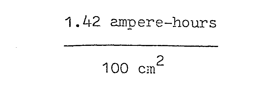
- Operating electrolyte (H2SO4) will have a specific gravity of 1.320. The portion of this electrolyte utilized at the 10-hour rate will be approximately 80%. Therefore, 8.8 g or 6.7 cm3 of electrolyte must be absorbed in separator means on each side of the positive plate. Assuming that the separator means comprises glass wool of 85% porosity, the separator means may be 0.4 mm thick, and the total weight of separator means including electrolyte will be 10.2 g/100 cm2.
- Characteristics of an electrode group comprising one
positive electrode 100 cm2 in area, onenegative electrode 100 cm2 in area, and two separators containing electrolyte will be as follows:
- As a more specific example of a "test cell, having specific parameters, a cell similar to that denoted by
arrow 14 in Figures 2 and 3 is constructed having electrodes fabricated from laminated foils as specified above.Positive electrode 16 andnegative electrodes 18 and 20 are initially identical in composition, and are 1 cm wide. Their length is chosen such that, when they are combined with a 0.4 mm thick separator means 22 as shown in Figure 4, those portions of their length which are adjacent to one another are 10 mm long, resulting in an active surface area of 10 cm 2. - It is pointed out that, although there are two
negative electrodes 18 and 20 present in such a cell, their outer lead layers which are closest to thewall portions 24 and 26 (these layers corresponding to those denoted by numerals 52' and' 54' in Figure 6) have no access to electrolyte, do not enter into the reactions, and are thus considered irrelevant in this example. The twonegative electrodes 18 and 20 thus will have the same total capacity as a single negative electrode as described in the foregoing general example. - After assembly, separator means 22 may be partially saturated with a formation electrolyte comprising H2S04 of 1.10 specific gravity, to which (8g KClO4)/(liter of H2S04) has been added. Since the area of the electrodes is 10 cm2 (per side) the expected capacity will be (0.80 amp-hrs) (10 cm2) or 0.08 ampere-hours.
Negative 100 cm 2 electrodes are to be formed to this value which, it will be recalled, corresponds to 80% formation and 70% utiliza-' tion of negative active material. Theoretical capacity of the electrodes is 0.142 ampere hours; thus an 80% formation will require approximately 0.12 ampere-hours of formation current. - The cell is connected to a power supply in the reversed polarity configuration as illustrated diagrammatically in Figure 11, and is charged with the negative electrodes connected as positive electrodes at 10 milliamperes for a period of 12 hours. Following this, the power supply is connected conventionally as indicated diagrammatically in Figures 12-13 and charged at 10 milliamperes for 24 hours such that substantially all of the lead of the positive electrode becomes transformed into Pb02. After the electrolyte gravity has been adjusted to an operating specific gravity of 1.320, a capacity of 0.081 ampere-hours at the 10-hour rate is realized.
- It is pointed out that the separator means 22, being 0.4mm thick, is capable of absorbing an amount of operating electrolyte substantially in excess of that required by the electrodes while being no more than 80% saturated with the said electrolyte. Therefore, in order to provide a path for oxygen transport from the positive electrodes to the negative electrode during charging, separator means 22 will be no more than 80% saturated with the operating electrolyte.
- To further establish the practicality of this invention, an additional calculation may be set forth showing the voltage drop caused by the utilization of Pb02 as the current carrier in the positive electrode. At the one hour rate the cell may be assumed to have a capacity of 0.05 ampere-hours. The non-reacting PbO2 portion (worst case, i.e. end of discharge) will have a resistance of 0.4 ohms. The resistive voltage drop at this time will thus be (0.05 amperes) (0.4 ohms) = 0.02 volts, and therefore is not considered to be detrimental to operation.
- As previously disclosed, the Pb02 of the positive electrode may comprise either α-PbO2, more porous β-PbO2, or a combination thereof. It is commonly assumed that the more porous material (β-PbO2) will have a lower conductivity than the less porous α-PbO2. It is known to the battery art, however, that β-PbO2, when maintained in a relatively confined state, will have a conductivity at least equivalent to that of α-PbO2; thus either form of Pb02 will be operable.
- It has earlier been pointed out that the composite lead foils of the invention may be produced by various means, and that negative electrodes may be separately formed using dummy positive electrodes. It is hereby also disclosed that positive electrodes may be directly produced by deposition or application of Pb02 layers of sufficient thickness directly upon a suitable substrate.
- Similar principles may be applied to larger batteries such as mine lamp batteries. One such
mine lamp battery 68 is illustrated in Figure 15. -
Battery 68 comprises two cells, 70 and 72, in acommon jar 74 of a suitable material, for example polycarbonate, internally divided by apartition 76 and having abottom cap portion 78 and topcell cover portion 80.Bottom cap portion 78 and atop cell portion 80 may be affixed tojar 74 by means of solvent cementing, ultrasonic welding, or other means. - Extending through holes in top
cell cover portion 80 are positive and negativeterminal posts battery 68 to a suitable load or to charging means. Terminal posts 82 and 84 may be sealed tocell cover portion 80 by any conventional means, forinstance epoxy resin 86. In addition, each cell may be provided with a sealable filling port as 100 at top and bottom thereof. - There are provided a plurality of positive and
negative electrodes 88 of foil construction, as well as separator means and electrolyte. The positive electrodes may be connected electrically to one another and topositive port 82 by suitable means such as, for example, alead bridge 90. Negative electrodes may be connected together by similar means. - Figure 16 illustrates a cross-section of an upper portion of one cell of a similar battery, in which a plurality of
positive electrodes 92,negative electrodes 94 and electrolyte-bearing separator means 96 are provided in a jar 98. Positive andnegative electrodes substrate 102 and two outer layers ofmetallic lead 104. - Interconnecting the
positive electrodes 92 is a lead bridge 106, for example, cast or soft welded to upper ends of thepositive electrodes 92, such that upper ends of their outer lead layers 104 become integrated with the lead mass of the bridge 106. Protruding from an upper side of lead bridge 106 is a terminal post 108, which extends throughcell cover 110. Sealing between post 108 andcell cover 110 may be accomplished in a conventional manner, such as by the use ofepoxy resin 112. - Figure 17 illustrates, in an inverted position, a lower portion of the
battery 68 of Figure 15, partially broken away. As was pointed out with respect to Figure 15,battery 68 comprises twocells common jar 74, the cells being separated from one another byinternal partition 76. - Each cell includes a plurality of positive and negative electrodes of foil construction, as well as separator means. In
cell 72 of Figure 17 is illustrated a plurality ofnegative electrodes 114, interconnected to one another by alead bridge 116 which may be affixed to these electrodes in the manner disclosed with respect to Figure 16. Protruding from one side ofbridge 116 is aterminal post 118, which extends through bottom wall 120 ofjar 74, and which is sealed to bottom wall 120 in a conventional manner. - Shown in
cell 70 is onenegative electrode 122 and onepart 124 of separator means. Also shown is a plurality ofpositive electrodes 126, which may be interconnected to one another by means of alead bridge 128, having a terminal post 130, in the manner previously disclosed. - Each cell includes an electrode group internally disposed therein and comprising a plurality of positive electrodes, negative electrodes and separator means interleaved with one another and positive and negative interconnecting lead bridges with their associated terminal posts. All of such electrode groups are identical in composition to one another, although adjacent cells will contain electrode groups which are in an inverted position with respect to one another. In this manner cell interconnections may be simplified. For example, Figure 17 shows that the negative
terminal post 118. ofcell 72 and the positive terminal post 130 ofcell 70 lie adjacent to one another, and may be connected to one another by means of a lead connecting link 132, which may be fused to the said terminal posts in a conventional manner. If additional cells are to be employed, those cells which are to be electrically connected to one another in series should be located adjacent to one another and should have their internal electrode groups inverted with respect to one another. Connecting links in this series configuration will alternate between upper and lower parts of the battery. - Each cell may also include sealable filling ports as 100', Figure 17, at its bottom portion, as previously disclosed.
Sealable filling ports 100, 100' referred to above may be utilized in one desirable mode for introducing formation electrolyte into the. cells, removal of the formation electrolyte after formation has been carried out and for introducing operating electrolyte into the cells. When these steps have been carried out ports as 100 and 100' may be sealed. These ports, in sealed state, may be designed to function as "blow off valves to relieve extreme internal gas overpressures. - A typical battery for mine lamp use similar to
battery 68 of Figure 15 may include for example two cells, each containing 34 positive electrodes, each electrode having an active surface area of 5.7 cm x 16.4 cm equalling 93.48 cm2, fabricated from foils as specified above. Also included may be 35 negative electrodes having a similar active surface area, and interleaved separator means. The total positive surface area will be 34 x 93.48 which equals 3.78 cm2. Since the electrode group will have a capacity of 0.8 ampere-hour per 100 cm2 of positive surface area at the 10-hour rate, the expected capacity will be.
- The total weight of the electrode groups for the two cells, including electrolyte, will be approximately 1.6 kilograms.
- The above battery is designed to have the same dimensions, and thus the same volume, as a conventional mine lamp battery. This leads to some important comparisons whereby conventional ratio values are taken with reference to an index of 1.0:

- Thus, the battery of the invention clearly meets the stated objectives of increasing power-to-weight and power-to-volume ratios.
- As previously noted, one important object of this invention is to develop a battery construction which will resist "zreeing". This "treeing" phenomenon is one of the primary causes of failure in conventional lead-acid batteries which are deeply cycled, and results from the fact that the electrolyte in a deeply discharged battery may suffer from an extreme depletion of sulfate ions available for reaction.
- As the sulfate ions become depleted due to the wellknown double-sulfate reactions, the specific gravity of the H2SO4 electrolyte decreases, approaching the standard 1.0 of water. This, in turn, allows the lead of the negative electrode to form soluble lead hydrates, for example Pb(OH)2, rather than PbSO4. These hydrates may then penetrate the formaninous separator means. Upon recharge, these hydrates will be transformed into lead and, after a sufficient amount of charge-discharge cycles, a bridge or "tree" of lead may be formed through the separator means thereby connecting the positive and negative electrodes to one another, producing an internal short-circuit within the battery cell.
- Sealed or semi-sealed batteries utilizing a "starved electrolyte principle, where the depth of discharge is deliberately limited by the amount of available sulfate ions, are extremely susceptible to this phenomenon. Should this principle be applied in a battery of the invention, where the distance between adjacent positive and negative electrodes is so small (e.g. 0.4 millimeters), treeing might severely shorten life.
- The potential for treeing may be significantly reduced or eliminated in any conventional battery by: (1) providing an excess of available sulfate ions in the electrolyte, for example, by the addition of a salt such as MgS04; (2) by limiting the depth of discharge such that there are always sufficient sulfate ions available in the electrolyte; or (3) by a combination of (1) and (2) above. In this manner the formation of soluble lead hydrates may be precluded, and treeing substantially eliminated.
- A salt such as MgS04 may, of course, be added to the electrolyte of a battery of the invention. However, the second procedure noted above is an inherent feature of a properly-designed battery of the invention in that, as previously disclosed, the depth of discharge is limited by the amount of reactive lead provided in the reactively retarded negative electrode. The amount of sulfuric acid (H2SO4) electrolyte absorbed in the separator means is significantly greater than that amount required to discharge the battery to this limit, and thus no soluble lead hydrates can be formed.
- As previously noted, one object of this invention is to make a sealed lead-acid battery. The "oxygen cycle" of gas recombination in such batteries, wherein oxygen evolved at the positive electrodes during charging becomes recombined with hydrogen at the negative electrodes to form water, is well-known to the art. Conditions prerequisite to such recombination include (1) a large surface area for the negative electrodes, and (2) a relatively easy path of travel for the oxygen between the positive and negative electrodes. Also desirable may be some overpressure, e.g. an overpressure within a range of from 0.1 kilograms per square centimeter to 5.0 kilograms per square centimeter in the battery.
- It will be apparent that a battery of the invention possesses a large amount of negative surface area, since the electrodes are so thin. The numerical example cited with respect to Figure 15, for instance, possesses a negative surface area of 3.78 cm2. The distance between positive and negative electrodes in the same example is 0.4 mm, comprising foraminous separator means only partially saturated with electrolyte, and thus the oxygen will have good access to the negative surfaces. In addition, provision made for sealing via sealed ports as 100, 100? (Figures 15 17) may permit a desired releasable over-pressure.
- Another stated object of the invention is to provide a battery which is capable of more rapid discharging and recharging than is possible with conventional batteries. Discharge and recharge rates are highly dependent upon the surface area of the electrodes with respect to the weight of active material in the electrodes. It is pointed out that foil electrodes of the nature disclosed in this specification possess an extremely great surface area, and thus discharging and recharging at faster rates will be facilitated.
- As previously disclosed, foil electrodes for a battery of the invention may be provided in various forms. The first example shown, that denoted by
arrow 32 in Figure 5, comprises twoouter layers plastic substrate 34. It should be observed that in some instances, for example when the lead layers are to be added to the substrate by a rolling process, it may be desirable to provide the plastic substrate with perforated holes in which the outer lead layer may become rooted. - Other forms of foils are possible, and may in fact be desirable for certain applications. In certain cases, for example for negative electrodes or for positive electrodes which are to be very tightly confined, a , substrate may not be necessary. Normally, however, some form of substrate is desirable to facilitate handling during manufacture and, in the case of positive electrodes, the formed Pb02 may be quite brittle, thus requiring a substrate to preserve the integrity of the electrode.
- Since the substrate may be required to function both as a reinforcement of the lead layers and of the Pb02 layers produced in the positive electrode by electrochemical formation, it is important to provide a good bond between the substrate and the outer lead layers before formation. It has been found that, in a rolled foil, this bond may be enhanced by perforating the substrate prior to application of the lead layers. During the rolling process the opposing lead layers are forced into contact with one another through the perforations in the substrate and thus become integrated and bonded to one another by the pressure applied by the rollers.
- In a preferred embodiment, however, the foils are mechanically modified prior to electrochemical formation such that the lead layers become rooted in the substrate. This modification is appropriate for foils produced by any of the methods disclosed above.
- Figure 17A illustrates a portion of a
lead foil body 75, modified to provide this rooted relationship. - As shown in Figure 17A,
foil body 75 has, at itsupper side 77, been pierced by a needle or other implement such that bothupper lead layer 79 andsubstrate 81 have been deformed downwardly, so as to extend into lower lead layer 83. The hole produced by the needle actually extends entirely through the foil body at this point in the process. - It is pointed out that, at this time, there will be an annular (or other configuration) ridge of lead (primarily coming from layer 83) formed around the edge of the
hole 85 at the lower surface 87 of Figure 17A. This ridge may then be wiped over or otherwise flattened out to substantially close the hole, as indicated atarrow 89, thereby to provide an annular zone of intimate contact or bond betweenlayers 79 and 83 as indicated by thearrows 91. It is well-known in the art that when lead is electrochemically formed into PbO2 the Pb02 will expand and seek to occupy a larger volume than the original lead. In thepresent invention hole 85 remains open atupper surface 77, and thus provides an expansion chamber which may become filled with Pb02 during electrochemical formation of a positive electrode, as indicated by dashedline 93. - Another form of foil electrode including a substrate comprises a laminate 134 shown in Figure 18, in which a
plastic substrate 136 has affixed to one side thereof a single layer oflead 138. Such laminates may be arranged in pairs in abutting relationship to one another such that plastic sides are adjacent to one another to comprise electrodes and an enhancement of the bond between the lead layers and the substrate may be realized as noted above. - Still another form comprises the configuration denoted by the
arrow 140 in Figure 19. In this form asubstrate 142 actually comprises separator means, to one side of which has been applied alayer 144 of lead.Substrate 142 may consist of any appropriate foraminous material such as needle-punched polyester, glass wool, etc. Since these substrates are foraminous, and thus their surfaces are somewhat irregular, adherence of the lead layer to the substrate may be enhanced. In addition, there may result a savings in cost, volume and weight, since the non-operative plastic substrates of previously disclosed forms have been eliminated. It is also pointed out that the substrate may comprise fibrous material, mesh, etc. - To simplify construction of batteries using this form of foil electrode, one edge may be rolled or folded over to produce a configuration such as that denoted by the
arrow 146 in Figure 20. It is pointed out that thelead layer 148 of such a folded electrode will be on the outer side of the folded portion. Two such folded electrodes, 150 and 152, may be combined in abutting relationship, as shown in Figure 21, such that their respective lead layers 154 and 156 are adjacent to one another, thus producing acompound electrode 158. - One cell of a retangular prismatic mine lamp battery, similar to
battery 68 of Figure 15 but using such folded electrodes having separator means as a substrate, is denoted by thearrow 160 in the cross-sectional view of Figure 22. Details of construction are similar in all aspects to those shown in Figures 15-17, except that the electrodes and separator means shown in these Figures have been replaced by folded electrodes similar toelectrodes - In Figure 22 are shown a plurality of pairs of folded
electrodes 162. Each pair comprises two folded electrodes having layers oflead 164 affixed to separator-substrate means 166, the folded electrodes of each pair being arranged in abutting relationship with one another in a configuration similar to that shown in Figure 21. These pairs are employed as positive electrodes. Similar pairs ofelectrodes 170 are shown in an inverted position, interleaved between the positive electrode pairs 162, and are employed as negative electrodes. On opposite sides of the electrode group are outernegative electrodes electrode 146 in Figure 20. - Adjacent laminated foils of opposing polarity are terminated and arranged such that
spaces 176 remain between the ends of these electrodes. - It is pointed out that, in this arrangement, separator-
substrates 166 of the positive electrodes abut separator-substrates of the negative electrodes, thus in effect acting as separator of double thickness. Separator-substrate thickness will, therefore, be selected such that the combination of two such substrates results in separator means of a require dimension. - It may be desired to fabricate batteries of the invention in which individual cells may have a generally cylindrical configuration. Figure 23 illustrates a four-volt mine lamp battery, generally denoted by the
arrow 178, comprising twosuch cells cell 182. In each cell the arrangement of electrodes and separator means is of the configuration known to the art as "jelly-roll"; such an arrangement, partially unrolled, is denoted at 180 in Figure 24. - Referring in detail to Figures 23 to 25 the
battery 178 comprises the two cells, 182 and 184, in acommon jar 186 having acell cover 188 including asealable port 214 which may also comprise one-way pressure release valve means, and its upper end and abottom cap 190 at its lower end. Thebottom wall 216 ofjar 186 is also provided withsealable ports 218, one for each cell. The "jelly-roll" 180 comprises four strips ofo material combined and rolled as shown. Thestrip 192, which will become a positive electrode after formation, comprises a laminated lead foil similar to that illustrated in Figure 5, having aplastic substrate 194 withlayers strip 200, which will after formation become a negative electrode, is a similar construction having aplastic substrate 202 withlayers -
Strips layers 196 of lead will be adjacent to one another separated only by aspace 212, the dimension of which space will depend upon the tightness of the roll. - The
strips strip 192 is the uppermost extremity ofroll 180 and the lower edge ofstrip 200 is the lowermost extremity of the said roll. Separator means 208, 210 are arranged such that some portions of these strips is always found between adjacent surfaces of the foil strips 192, 200. - A battery of this nature, made with laminated foils and separator means previously specified having a height of 150 mm and wrapped to a diameter of 50 mm, will have a capacity of 22.5 ampere-hours at the 10-hour rate. Assuming that the capacity at the one-hour rate will be 15 ampere-hours, the total voltage drop due to the use of Pb02 as a current collector will be 0.048 volts at the one-hour rate which is `negiligible.
- It has earlier been disclosed that different forms of foil electrodes may be utilized in batteries of the invention; this applies to batteries having electrode groups of the "jelly-roll" type as well as to those utilizing electrode groups comprising interleaved sheets of electrode material. Figure 26 illustrates, partially unrolled, a jelly-roll electrode group.236, comprising four folded electrode strips 238, 240, 242, 244 similar to the
strip 146 in Figure 20. The four strip are arranged in pairs, similar to Figure 21, to comprise twocompound electrodes - A
cylindrical battery 250 of the invention in a single-celled configuration somewhat similar to that of conventional single-celled batteries is illustrated in Figure 27, and is shown in cross-section in Figure 28. - The electrode group construction shown in Figure 28 is similar to that denoted at 236 in Figure 26. One pair of
strips 252 corresponding to strip 248 of Figure 26, functions as a negative electrode, and another pair ofstrips 254 corresponding to strip 246 of Figure 26, functions as a positive electrode. Separator-substrates - Upper edges of the wrapped
positive electrodes 254 are interconnected by alead bridge 264, which may be a complete disc, and which includes a positiveterminal post 266.Bridge 264 may be cast or soft-welded in place such that lead layers 268 and 270 of the positive electrodes become integrated into the mass of the said bridge. Asimilar bridge 272, including a negativeterminal post 274, is combined with the lower edge ofnegative electrode 252 in a similar manner. - The electrode group is confined first within a relatively thin
inner enclosure body 276, comprising a cylinder of a plastic material chemically inert to H2SO4 such as polyester or a polyolefin, open at one end and having aninner cover 278 of a similar material affixed to and substantially closing the open end.Inner cover 278 andbottom wall 280 of theinner enclosure body 276 has holes through which positiveterminal post 266 and negativeterminal post 274, respectively, extend. Formation electrolyte may be introduced via openings around these posts in a manner similar to that earlier disclosed; Plante formation of the invention may then be caused to take place, and the formation electrolyte removed and replaced by an operating electrolyte through these same openings. - The formed battery may then be further enclosed in a relatively strong outer
cylindrical container 282, openat one end, which may be fabricated for example from aluminum or steel.Container 282 has a hole at its bottom through which negativeterminal post 274 extends. Anupper closure part 284 of a similar material, pierced to allowpositive post 266 to extend therethrough, is provided, at the open end of outercylindrical container 282, and is held in place by clinching over theupper extremity 286 of theouter container 282 as shown. After the battery has been electrochemically formed and an operating electrolyte introduced, the openings aroundterminal posts inner cover 278 andupper closure part 284 and toinner enclosure body 276 andouter container 282, respectively, by employment of a suitable insulating and sealing compound such asepoxy resin 288. - A similar battery may be constructed utilizing an electrode group of the type denoted at 290 in Figure 29, comprising two
strips strip 146 of Figure 20. Such a battery is indicated at 296 in the cross-sectional view of Figure 30 in which strip 292 functions as a positive electrode, and strip 294 functions as a negative electrode. - Batteries of the invention similar in nature to the jelly-roll nature previously described, but having cross-sections of differing configurations, may also be produced. On such battery, having an elliptical cross-section, is denoted by
arrow 298 in Figure 31. An electrode group for such a battery may be produced by wrapping interlayered strips of electrode material and separator means, shown diagrammatically at 300 in Figure 32, about amandrel 302, then adding appropriate bridges, etc, and placing the said electrode group into an appropriately-shaped container in the manner previously disclosed. The mandrel may be removed or, if it is of a suitable material, allowed to remain in place. Alternatively, a jelly-roll. having a round cross-sectional configuration may be reformed into a different shape by the application of external pressure prior to the addition of interconnecting lead bridges. - Reactively retarded foil electrodes of the invention may be fabricated having various thicknesses of lead layers. An appropriate range for such thicknesses may be between 4 and 300 microns.
- Disclosed herewith are two additional numerical examples, specifying lead thicknesses of different dimension, denoted as Examples A and B.
- Positive electrodes are fabricated from a laminated foil having layers of lead, 60 microns thick, affixed to each side of a 20 micron thick plastic substrate. The total thickness of such a foil, prior to formation, will be 0.14 mm. After Plante formation to a depth of 50 microns, the total thickness will be 0.25 mm and the theoretical capacity 2.89 ampere-hours/100 cm2. Any lead remaining in the positive electrodes after Plante formation will become totally oxidized to Pb02 after a few charge-discharge cycles. Since the negative electrodes will be utilized to limit the depth of discharge of the positive electrodes, the actual usable capacity of the positive electrodes will be 1.7 ampere-hours/100cm2 and their weight will be 15.9g of lead/100 cm2.
- Negative electrodes are fabricated from a laminated foil having layers of
lead 50 microns thick affixed to each side of a 20 micron thick plastic substrate. The thickness of such a foil, prior to formation, will be 0.12 mm. After Plante formation to a depth of 40 microns, the total thickness will be 0.2 mm, and the weight will be 8.8g of lead/100 cm2. - The operating electrolyte to be employed will be H2S04 of 1.320 specific gravity. In order to obtain a capacity of 1.7 ampere-hours/100 cm2 and still limit electrolyte utilization to 80%, the required thickness for separator means will be 0.65 mm; the weight of two such separators, including the operating electrolyte, will be 16g/100 mm2.
- The total weight of an electrode group comprising one positive electrode, one negative electrode and two separators containing an operating electrolyte will be 43g/100 cm2. Energy density (without jar) will be 79 watt hours/kg.
- The electrodes may be Plante formed using sodium perchlorate or organic acids as forming agents in the formation electrolyte. Organic acids will gradually be oxidized, and sodium perchlorate may be either washed away or left in the battery, as previously disclosed.
- Positive and negative electrodes are fabricated from laminates comprising layers of lead 4 microns thick affixed to each side of a 13 micron thick plastic substrate. When the lead present in the positive electrode has been formed to Pb02, 50% of such Pb02 will be util- ized as active material (reacting Pb02) and the remaining 50% (non-reacting Pb02) will be utilized as current-carrying means. Formed capacity of the electrodes will be limited by the negative electrodes to 0.06 ampere-hours/100 cm2. Employing separator means 50 microns thick, the energy density will be 71 watt-hours/kg or 0.17 watt-hours/cm3. In a cell of "jelly-roll" construction the energy density will be approximately 65 watt-hours/kg. The capacity at the 10-minute discharge rate will be 80% of the capacity at the 3-hour rate, and even higher discharge rates may be possible.
- The advantages accruing to this example include a minimal change in capacity with differing discharge rates and a very rapid formation and recharge capability.
- As previously noted, one object of the invention is to devise a method of forming lead-acid batteries wherein environmental as well as health hazards may be substantially controlled or eliminated. The most prevalent of such hazards present in conventional battery constructional battery construction is the presence of free lead particles or lead oxide which may occur as airborne respirable particles or as ingestable material. The use of foil batteries as electrode material precludes the occurrence of such free lead particles. In a preferred embodiment, wherein formation of the lead of positive electrodes to Pb02 takes place in situ within a cell body, no free Pb02 will be present in the manufacturing environment of a battery of the invention.
- Patticularly in the case of batteries of the' invention employing electrode groups of a "jelly-roll" construction, as'sembly of the electrode groups may easily be automated to a degree that manufacturing personnel will only come into contact with lead during loading and unloading of the automated equipment. In this manner, it will be seen that exposure to lead and/or lead oxides, common to conventional battery manufacture, is avoided.
- It is further pointed out that in a battery of the invention, reactivity retardation of the positive electrodes is essential. As earlier disclosed, in a preferred embodiment of the invention reactivity retardation of the positive electrodes is accomplished by the use of reactively retarded negative electrodes. However, positive electrodes may be reactively retarded by limiting the degree of discharge of the said positive electrodes without being subject to control by the negative electrodes. This may be done, for example, by utilizing external electrical circuit means such as electrical timing means. In this manner, non-reacting Pb02 portions of positive electrodes may be achieved and maintained while the negative electrodes may be reduced in mass and current-carrying capability.
Claims (26)
Applications Claiming Priority (2)
| Application Number | Priority Date | Filing Date | Title |
|---|---|---|---|
| SE8005528A SE8005528L (en) | 1980-08-01 | 1980-08-01 | ELECTRICAL BLYACK CUMULATOR WITH THIN ELECTRODES |
| SE8005528 | 1980-08-04 |
Publications (2)
| Publication Number | Publication Date |
|---|---|
| EP0051349A1 true EP0051349A1 (en) | 1982-05-12 |
| EP0051349B1 EP0051349B1 (en) | 1986-09-10 |
Family
ID=20341512
Family Applications (1)
| Application Number | Title | Priority Date | Filing Date |
|---|---|---|---|
| EP81303302A Expired EP0051349B1 (en) | 1980-08-01 | 1981-07-17 | A lead - acid battery construction |
Country Status (8)
| Country | Link |
|---|---|
| EP (1) | EP0051349B1 (en) |
| JP (1) | JPS5763777A (en) |
| AT (1) | ATE22199T1 (en) |
| CA (1) | CA1163319A (en) |
| DE (1) | DE3175298D1 (en) |
| DK (1) | DK340781A (en) |
| SE (1) | SE8005528L (en) |
| ZA (1) | ZA814934B (en) |
Cited By (6)
| Publication number | Priority date | Publication date | Assignee | Title |
|---|---|---|---|---|
| GB2261541A (en) * | 1991-10-22 | 1993-05-19 | Gorodskoi Studenchesko Molodez | Manufacture of lead-acid battery electrode |
| EP0494147A4 (en) * | 1989-06-14 | 1994-07-13 | Tristan E Juergens | Ultra-thin plate electrochemical cell and method of manufacture |
| EP0664054A4 (en) * | 1991-09-10 | 1995-03-08 | Bolder Battery Inc | Battery end connector. |
| EP0676821A1 (en) * | 1994-03-09 | 1995-10-11 | Wolfgang Herrmann | Electrochemical current source |
| WO2000008704A1 (en) * | 1998-08-06 | 2000-02-17 | Hawker Energy Products, Inc. | Wound lead acid battery with non-circular cells |
| EP0961335A3 (en) * | 1989-06-14 | 2003-10-29 | GP Batteries International Limited | Ultra-thin plate electromechanical cell and method of manufacture |
Citations (9)
| Publication number | Priority date | Publication date | Assignee | Title |
|---|---|---|---|---|
| FR328250A (en) * | 1903-01-03 | 1903-07-08 | Charles Coster | Accumulator plate and its manufacturing method |
| FR516163A (en) * | 1920-05-31 | 1921-04-14 | Gustave Philippart | Improvements made in the establishment of secondary batteries called electric accumulators |
| US2883443A (en) * | 1956-07-13 | 1959-04-21 | Ruetschi Karl | Lead-acid storage battery |
| GB1144438A (en) * | 1965-05-07 | 1969-03-05 | Bosch Gmbh Robert | Improvements in or relating to electrical storage batteries |
| US3447969A (en) * | 1966-11-17 | 1969-06-03 | Us Navy | Storage battery improvement |
| US3536531A (en) * | 1968-05-30 | 1970-10-27 | Matsushita Electric Industrial Co Ltd | Lead storage battery and a method of producing the electrodes thereof |
| FR2203178A1 (en) * | 1972-10-13 | 1974-05-10 | Varta Batterie | Bipolar lead-acid accumulator electrode - using separator with twin conduc-tive foils at least one of which has lead-oxide as conductor |
| US4121019A (en) * | 1977-07-20 | 1978-10-17 | Garrett Plante Corporation | Lead-acid storage battery |
| FR2391567A1 (en) * | 1977-05-18 | 1978-12-15 | Scholl Dr Ing Gunter | ELECTRIC ACCUMULATOR |
-
1980
- 1980-08-01 SE SE8005528A patent/SE8005528L/en not_active Application Discontinuation
-
1981
- 1981-07-17 AT AT81303302T patent/ATE22199T1/en not_active IP Right Cessation
- 1981-07-17 EP EP81303302A patent/EP0051349B1/en not_active Expired
- 1981-07-17 DE DE8181303302T patent/DE3175298D1/en not_active Expired
- 1981-07-20 ZA ZA814934A patent/ZA814934B/en unknown
- 1981-07-30 JP JP56119995A patent/JPS5763777A/en active Pending
- 1981-07-30 DK DK340781A patent/DK340781A/en not_active Application Discontinuation
- 1981-07-31 CA CA000382956A patent/CA1163319A/en not_active Expired
Patent Citations (9)
| Publication number | Priority date | Publication date | Assignee | Title |
|---|---|---|---|---|
| FR328250A (en) * | 1903-01-03 | 1903-07-08 | Charles Coster | Accumulator plate and its manufacturing method |
| FR516163A (en) * | 1920-05-31 | 1921-04-14 | Gustave Philippart | Improvements made in the establishment of secondary batteries called electric accumulators |
| US2883443A (en) * | 1956-07-13 | 1959-04-21 | Ruetschi Karl | Lead-acid storage battery |
| GB1144438A (en) * | 1965-05-07 | 1969-03-05 | Bosch Gmbh Robert | Improvements in or relating to electrical storage batteries |
| US3447969A (en) * | 1966-11-17 | 1969-06-03 | Us Navy | Storage battery improvement |
| US3536531A (en) * | 1968-05-30 | 1970-10-27 | Matsushita Electric Industrial Co Ltd | Lead storage battery and a method of producing the electrodes thereof |
| FR2203178A1 (en) * | 1972-10-13 | 1974-05-10 | Varta Batterie | Bipolar lead-acid accumulator electrode - using separator with twin conduc-tive foils at least one of which has lead-oxide as conductor |
| FR2391567A1 (en) * | 1977-05-18 | 1978-12-15 | Scholl Dr Ing Gunter | ELECTRIC ACCUMULATOR |
| US4121019A (en) * | 1977-07-20 | 1978-10-17 | Garrett Plante Corporation | Lead-acid storage battery |
Cited By (8)
| Publication number | Priority date | Publication date | Assignee | Title |
|---|---|---|---|---|
| EP0494147A4 (en) * | 1989-06-14 | 1994-07-13 | Tristan E Juergens | Ultra-thin plate electrochemical cell and method of manufacture |
| EP0961335A3 (en) * | 1989-06-14 | 2003-10-29 | GP Batteries International Limited | Ultra-thin plate electromechanical cell and method of manufacture |
| EP0961336A3 (en) * | 1989-06-14 | 2003-10-29 | GP Batteries International Limited | Ultra-thin plate electromechanical cell and method of manufacture |
| EP0664054A4 (en) * | 1991-09-10 | 1995-03-08 | Bolder Battery Inc | Battery end connector. |
| GB2261541A (en) * | 1991-10-22 | 1993-05-19 | Gorodskoi Studenchesko Molodez | Manufacture of lead-acid battery electrode |
| GB2261541B (en) * | 1991-10-22 | 1995-05-17 | Gorodskoi Studenchesko Molodez | Manufacture of lead-acid battery electrode |
| EP0676821A1 (en) * | 1994-03-09 | 1995-10-11 | Wolfgang Herrmann | Electrochemical current source |
| WO2000008704A1 (en) * | 1998-08-06 | 2000-02-17 | Hawker Energy Products, Inc. | Wound lead acid battery with non-circular cells |
Also Published As
| Publication number | Publication date |
|---|---|
| ZA814934B (en) | 1983-02-23 |
| CA1163319A (en) | 1984-03-06 |
| EP0051349B1 (en) | 1986-09-10 |
| DK340781A (en) | 1982-02-05 |
| DE3175298D1 (en) | 1986-10-16 |
| JPS5763777A (en) | 1982-04-17 |
| SE8005528L (en) | 1982-02-05 |
| ATE22199T1 (en) | 1986-09-15 |
Similar Documents
| Publication | Publication Date | Title |
|---|---|---|
| US5047300A (en) | Ultra-thin plate electrochemical cell | |
| US4964878A (en) | Lead-acid rechargeable storage battery | |
| KR100349755B1 (en) | Anode Electrochemical Battery for Stacked Wafer Cell | |
| US4977043A (en) | Rectangular sealed alkaline storage battery with negative electrode comprising hydrogen storage alloy | |
| US6949313B2 (en) | Battery with a microcorrugated, microthin sheet of highly porous corroded metal | |
| US20030013015A1 (en) | Bipolar electrochemical battery of stacked wafer cells | |
| JP3265430B2 (en) | Air-assisted alkaline battery | |
| EP0251683B1 (en) | High rate sealed lead-acid battery with ultrathin plates | |
| IL109845A (en) | Rechargeable electrochemical cell | |
| US5368961A (en) | Thin plate electrochemical cell | |
| EP0916164A1 (en) | Calcium-zincate electrode for alkaline batteries and method for making same | |
| JPH0457072B2 (en) | ||
| EP0573040A1 (en) | A positive electrode for lithium secondary battery and its method of manufacture, and a nonaqueous electrolyte lithium secondary battery employing the positive electrode | |
| US5993494A (en) | Method of manufacturing modular components for a bipolar battery and the resulting bipolar battery | |
| US20030059674A1 (en) | Electrode having expanded surface area and inner chamber encapsulating a highly reactive material for use in a liquid electrolyte battery | |
| US3536531A (en) | Lead storage battery and a method of producing the electrodes thereof | |
| US2883443A (en) | Lead-acid storage battery | |
| US4411969A (en) | Battery construction characterized by reactively limited gridless electrode means, and methods of making and operating same | |
| EP0051349A1 (en) | A lead - acid battery construction | |
| US5429894A (en) | Silver-iron battery | |
| EP0301647B1 (en) | Electrochemical cell | |
| US4194060A (en) | Electric accumulator and storage cell | |
| EP0024407B1 (en) | Lead acid electric storage batteries | |
| US7879497B2 (en) | Battery | |
| JP7724280B2 (en) | Zinc secondary battery |
Legal Events
| Date | Code | Title | Description |
|---|---|---|---|
| PUAI | Public reference made under article 153(3) epc to a published international application that has entered the european phase |
Free format text: ORIGINAL CODE: 0009012 |
|
| AK | Designated contracting states |
Designated state(s): AT BE CH DE FR GB IT LI NL SE |
|
| 17P | Request for examination filed |
Effective date: 19821007 |
|
| RAP1 | Party data changed (applicant data changed or rights of an application transferred) |
Owner name: KOEHLER MANUFACTURING COMPANY |
|
| GRAA | (expected) grant |
Free format text: ORIGINAL CODE: 0009210 |
|
| AK | Designated contracting states |
Kind code of ref document: B1 Designated state(s): AT BE CH DE FR GB IT LI NL SE |
|
| REF | Corresponds to: |
Ref document number: 22199 Country of ref document: AT Date of ref document: 19860915 Kind code of ref document: T |
|
| ITF | It: translation for a ep patent filed | ||
| REF | Corresponds to: |
Ref document number: 3175298 Country of ref document: DE Date of ref document: 19861016 |
|
| ET | Fr: translation filed | ||
| PLBE | No opposition filed within time limit |
Free format text: ORIGINAL CODE: 0009261 |
|
| STAA | Information on the status of an ep patent application or granted ep patent |
Free format text: STATUS: NO OPPOSITION FILED WITHIN TIME LIMIT |
|
| PGFP | Annual fee paid to national office [announced via postgrant information from national office to epo] |
Ref country code: NL Payment date: 19870731 Year of fee payment: 7 |
|
| 26N | No opposition filed | ||
| PG25 | Lapsed in a contracting state [announced via postgrant information from national office to epo] |
Ref country code: DE Effective date: 19880430 |
|
| PG25 | Lapsed in a contracting state [announced via postgrant information from national office to epo] |
Ref country code: GB Effective date: 19880717 Ref country code: AT Effective date: 19880717 |
|
| PG25 | Lapsed in a contracting state [announced via postgrant information from national office to epo] |
Ref country code: SE Effective date: 19880718 |
|
| PG25 | Lapsed in a contracting state [announced via postgrant information from national office to epo] |
Ref country code: LI Effective date: 19880731 Ref country code: CH Effective date: 19880731 Ref country code: BE Effective date: 19880731 |
|
| BERE | Be: lapsed |
Owner name: KOEHLER MFG CY Effective date: 19880731 |
|
| PG25 | Lapsed in a contracting state [announced via postgrant information from national office to epo] |
Ref country code: NL Effective date: 19890201 |
|
| NLV4 | Nl: lapsed or anulled due to non-payment of the annual fee | ||
| GBPC | Gb: european patent ceased through non-payment of renewal fee | ||
| PG25 | Lapsed in a contracting state [announced via postgrant information from national office to epo] |
Ref country code: FR Free format text: LAPSE BECAUSE OF NON-PAYMENT OF DUE FEES Effective date: 19890331 |
|
| REG | Reference to a national code |
Ref country code: CH Ref legal event code: PL |
|
| REG | Reference to a national code |
Ref country code: FR Ref legal event code: ST |
|
| EUG | Se: european patent has lapsed |
Ref document number: 81303302.4 Effective date: 19890510 |