EP0051186A1 - Hydraulic system comprising a locking device for maintaining a control valve in its working position - Google Patents
Hydraulic system comprising a locking device for maintaining a control valve in its working position Download PDFInfo
- Publication number
- EP0051186A1 EP0051186A1 EP19810108401 EP81108401A EP0051186A1 EP 0051186 A1 EP0051186 A1 EP 0051186A1 EP 19810108401 EP19810108401 EP 19810108401 EP 81108401 A EP81108401 A EP 81108401A EP 0051186 A1 EP0051186 A1 EP 0051186A1
- Authority
- EP
- European Patent Office
- Prior art keywords
- piston
- rod
- sleeve
- pressure
- pressure medium
- Prior art date
- Legal status (The legal status is an assumption and is not a legal conclusion. Google has not performed a legal analysis and makes no representation as to the accuracy of the status listed.)
- Granted
Links
Images
Classifications
-
- F—MECHANICAL ENGINEERING; LIGHTING; HEATING; WEAPONS; BLASTING
- F16—ENGINEERING ELEMENTS AND UNITS; GENERAL MEASURES FOR PRODUCING AND MAINTAINING EFFECTIVE FUNCTIONING OF MACHINES OR INSTALLATIONS; THERMAL INSULATION IN GENERAL
- F16K—VALVES; TAPS; COCKS; ACTUATING-FLOATS; DEVICES FOR VENTING OR AERATING
- F16K11/00—Multiple-way valves, e.g. mixing valves; Pipe fittings incorporating such valves
- F16K11/02—Multiple-way valves, e.g. mixing valves; Pipe fittings incorporating such valves with all movable sealing faces moving as one unit
- F16K11/06—Multiple-way valves, e.g. mixing valves; Pipe fittings incorporating such valves with all movable sealing faces moving as one unit comprising only sliding valves, i.e. sliding closure elements
- F16K11/065—Multiple-way valves, e.g. mixing valves; Pipe fittings incorporating such valves with all movable sealing faces moving as one unit comprising only sliding valves, i.e. sliding closure elements with linearly sliding closure members
- F16K11/07—Multiple-way valves, e.g. mixing valves; Pipe fittings incorporating such valves with all movable sealing faces moving as one unit comprising only sliding valves, i.e. sliding closure elements with linearly sliding closure members with cylindrical slides
- F16K11/0704—Multiple-way valves, e.g. mixing valves; Pipe fittings incorporating such valves with all movable sealing faces moving as one unit comprising only sliding valves, i.e. sliding closure elements with linearly sliding closure members with cylindrical slides comprising locking elements
-
- F—MECHANICAL ENGINEERING; LIGHTING; HEATING; WEAPONS; BLASTING
- F15—FLUID-PRESSURE ACTUATORS; HYDRAULICS OR PNEUMATICS IN GENERAL
- F15B—SYSTEMS ACTING BY MEANS OF FLUIDS IN GENERAL; FLUID-PRESSURE ACTUATORS, e.g. SERVOMOTORS; DETAILS OF FLUID-PRESSURE SYSTEMS, NOT OTHERWISE PROVIDED FOR
- F15B13/00—Details of servomotor systems ; Valves for servomotor systems
- F15B13/02—Fluid distribution or supply devices characterised by their adaptation to the control of servomotors
-
- Y—GENERAL TAGGING OF NEW TECHNOLOGICAL DEVELOPMENTS; GENERAL TAGGING OF CROSS-SECTIONAL TECHNOLOGIES SPANNING OVER SEVERAL SECTIONS OF THE IPC; TECHNICAL SUBJECTS COVERED BY FORMER USPC CROSS-REFERENCE ART COLLECTIONS [XRACs] AND DIGESTS
- Y10—TECHNICAL SUBJECTS COVERED BY FORMER USPC
- Y10T—TECHNICAL SUBJECTS COVERED BY FORMER US CLASSIFICATION
- Y10T137/00—Fluid handling
- Y10T137/8593—Systems
- Y10T137/86485—Line condition change responsive release of valve
Abstract
Description
Die Erfindung betrifft ein Hydrauliksystem mit einer Druckmittelquelle, einem Sumpf, einem Steuerventil mit bestimmten Arbeitsstellungen zur Steuerung des Druckmittelflusses zwischen Quelle, Sumpf und einem Hydromotor o.dergl., einer Druckmittelverbindung zwischen Quelle und Steuerventil, einer in eine Arretierstellung verschiebbaren Arretiervorrichtung, die das Steuerventil in zumindest einer seiner Arbeitsstellungen lösbar festhält, und mit einer hydromechanischen Einrichtung, die die Arretiervorrichtung über eine verschiebbar in einer Gehäusebohrung gelagerte Stange in ihre Arretierstellung drückt und eine Verschiebung des Steuerventils aus seiner ausgewählten Arbeitsstellung verhindert, wobei die hydromechanische Einrichtung ferner ein in der genannten Bohrung verschiebbares kolbenähnliches Bauteil aufweist, das auf der Stange geführt ist und in Abhängigkeit von einem auf seine beiden Seiten wirkenden Differenzdruck verschiebbar ist und dabei die Stange beaufschlagt.The invention relates to a hydraulic system with a pressure medium source, a sump, a control valve with certain working positions for controlling the pressure medium flow between the source, sump and a hydraulic motor or the like releasably holds in at least one of its working positions, and with a hydromechanical device which presses the locking device into its locking position via a rod which is displaceably mounted in a housing bore and prevents displacement of the control valve from its selected working position, the hydromechanical device furthermore inserting one into said bore has displaceable piston-like component which is guided on the rod and is displaceable as a function of a differential pressure acting on its two sides and thereby acts on the rod.
Eine derartige Ausführungsform läßt sich der deutschen Patentschrift 21 33 715 entnehmen. Dabei wird die Arretiervorrichtung von einem mit zwei sich gegenüberliegenden Druckseiten versehenen Kolben beaufschlagt, die jeweils dem Druck vor und hinter einem Mengenventil im Hydrauliksystem ausgesetzt sind, wobei das Steuerventil hinter dem Mengenventil angeschlossen ist. Die vor dem Mengenventil liegende Druckseite des Kolbens der hydromechanischen Einrichtung steht zusätzlich unter einem konstanten Federdruck; die Druckseite hinter dem Mengenventil weist eine größere Druckfläche auf als die Druckseite des Kolbens vor dem Mengenventil, wobei die Dimensionierung der Druckseiten so vorgenommen ist, daß sich die aus den am Kolben angreifenden hydraulischen Drücken stammenden Kräfte während des Arbeitsbetriebes, z.B. so lange der Hydromotor seine Endstellung noch nicht erreicht hat, im wesentlichen aufheben.Such an embodiment can be found in German Patent 21 33 715. The locking device is acted upon by a piston provided with two opposing pressure sides, each before and the pressure are exposed behind a quantity valve in the hydraulic system, the control valve being connected behind the quantity valve. The pressure side of the piston of the hydromechanical device located in front of the quantity valve is additionally under a constant spring pressure; the pressure side behind the quantity valve has a larger pressure area than the pressure side of the piston in front of the quantity valve, the dimensioning of the pressure sides being carried out in such a way that the forces arising from the hydraulic pressures acting on the piston occur during operation, for example as long as the hydraulic motor is operating Has not yet reached the end position, essentially cancel it.
Wenn bei dieser vorbekannten Einrichtung der Pumpendruck unter einen Schwellenwert absinkt, z.B. weil die Antriebsmaschine für die Hydraulikpumpe während des Hubes des Hydraulikzylinders abgeschaltet wird, dann wird die Arretiervorrichtung nicht automatisch gelöst, ermöglicht also nicht die automatische Rückstellung des Steuerventils in seine Neutralstellung. Dies ergibt sich aus der Tatsache, daß die auf das Steuerventil in dieser "abgeschlossenen" Stellung wirkenden Zentrierfedern und Hydraulikkräfte nicht groß genug sind, um die von der Feder der hydromechanischen Einrichtung ausgeübte Arretierkraft zu überwinden. Bei dem eingangs erläuterten Hydrauliksystem wird somit die Hydraulikfunktion lediglich durch erneutes Starten der Antriebsmaschine reaktiviert, ohne daß die Bedienungsperson das Steuerventil wissentlich in eine Arbeitsstellung zurückverschiebt.In this known device, if the pump pressure drops below a threshold, e.g. because the drive machine for the hydraulic pump is switched off during the stroke of the hydraulic cylinder, the locking device is not automatically released, and therefore does not enable the control valve to be automatically reset to its neutral position. This results from the fact that the centering springs and hydraulic forces acting on the control valve in this "closed" position are not large enough to overcome the locking force exerted by the spring of the hydromechanical device. In the hydraulic system explained at the outset, the hydraulic function is thus only reactivated by restarting the drive machine without the operator knowingly moving the control valve back into a working position.
Der Erfindung liegt somit die Aufgabe zugrunde, das eingangs beschriebene Hydrauliksystem so zu verbessern, daß bei Abfall des Systemdrucks während der Ausübung einer Hydraulikfunktion die Arretiervorrichtung automatisch gelöst wird und die Rückverstellung des Steuerventils in seine Neutralstellung zuläßt.The invention is therefore based on the object of improving the hydraulic system described at the outset so that when the system pressure drops while performing a hydraulic function, the locking device is automatically released and allows the control valve to be reset to its neutral position.
Diese Aufgabe wird gemäß der Erfindung durch folgende Merkmale gelöst:
- a) Die genannte Bohrung steht einerseits mit der Druckmittelverbindung und andererseits mit dem Sumpf in Verbindung;
- b) das kolbenähnliche Bauteil ist als Hülse ausgebildet, die zusammen mit der Bohrung sowie der Stange einen ersten, mit dem Sumpf in Verbindung stehenden Hohlraum sowie einen zweiten, mit der Druckmittelverbindung verbundenen Hohlraum bilden;
- c) die die Hülse verschiebende Druckdifferenz ergibt sich aus den Druckunterschieden in den beiden Hohlräumen.
- a) The hole mentioned is connected on the one hand to the pressure medium connection and on the other hand to the sump;
- b) the piston-like component is designed as a sleeve which, together with the bore and the rod, form a first cavity which is connected to the sump and a second cavity which is connected to the pressure medium connection;
- c) the pressure difference shifting the sleeve results from the pressure differences in the two cavities.
Die erfindungsgemäße Aufgabe kann aber auch dadurch gelöst werden, daß das kolbenähnliche Bauteil ein mit der Stange gekuppelter Kolben ist, der bei Vorwärtsströmung in der Druckmittelverbindung die Arretiervorrichtung in ihre Arretierstellung drückt, wobei die Verschiebung des Kolbens in Richtung auf die Arretiervorrichtung durch einen in der Bohrung vorgesehenen Anschlag begrenzt ist.However, the object of the invention can also be achieved in that the piston-like component is a piston coupled to the rod, which presses the locking device into its locking position when the pressure medium connection flows forward, the displacement of the piston in the direction of the locking device by a in the bore provided stop is limited.
Schließlich wird die der Erfindung zugrundeliegende Aufgabe auch durch folgende Merkmalskombination gelöst:
- a) Das zweite Ende der Gehäusebohrung ist an den Sumpf angeschlossen;
- b) in der Bohrung ist eine den Kolben umschließende Hülse verschiebbar gelagert, deren eines offenes Ende mit dem stromauf liegenden Abschnitt der Druckmittelverbindung in Verbindung steht, während sein anderes, mit dem Sumpf in Verbindung stehendes Ende halsförmig ausgebildet ist und mit einer Bohrung verschiebbar und abdichtend auf der Stange geführt ist;
- c) die Stange weist einen innerhalb der Hülse liegenden verdickten Abschnitt auf;
- d) der Kolben ist zwischen dem offenen Hülsenende und dem verdickten Stangenabschnitt verschiebbar, wobei seine Verschiebung zum offenen Hülsenende hin durch einen ersten Anschlag begrenzt ist;
- e) eine erste Feder stützt sich zwischen Kolben und verdicktem Stangenabschnitt ab;
- f) eine zweite Feder stützt sich zwischen dem ersten Anschlag und dem Kolben ab;
- g) in die Hülse mündet zwischen ihrem halsförmigen Ende und dem Kolben eine öffnung, die an den stromab liegenden Abschnitt der Druckmittelverbindung angeschlossen ist.
- a) The second end of the housing bore is connected to the sump;
- b) a sleeve surrounding the piston is slidably mounted in the bore, one open end of which is connected to the upstream section of the pressure medium connection, while its other end which is connected to the sump is neck-shaped and can be moved and sealed with a bore is guided on the pole;
- c) the rod has a thickened portion located within the sleeve;
- d) the piston is displaceable between the open sleeve end and the thickened rod section, its displacement towards the open sleeve end being limited by a first stop;
- e) a first spring is supported between the piston and the thickened rod section;
- f) a second spring is supported between the first stop and the piston;
- g) an opening opens into the sleeve between its neck-shaped end and the piston and is connected to the downstream section of the pressure medium connection.
Die bei dem erfindungsgemäßen Hydrauliksystem aufgebrachte Arretierkraft ist somit im wesentlichen hydraulischen Ursprungs. Bei der Arretiervorrichtung ist eine Vorspannung vorgesehen, die sich aus einem System-Sumpf Druckdifferential ergibt. Die auf das Steuerventil wirkenden Hydraulikkräfte werden durch die hydromechanische Einrichtung ausgeglichen. Ferner ist das neue System so ausgelegt, daß die Arretiervorrichtung in einem begrenzten Umfang auf Bedingungen bei rückwärtiger Strömung im System anspricht. Die Arretiervorrichtung kann nur von begrenzten Kräften beaufschlagt werden.The locking force applied in the hydraulic system according to the invention is therefore essentially of hydraulic origin. A preload is provided in the locking device, which results from a system sump pressure differential. The hydraulic forces acting on the control valve are balanced by the hydromechanical device. Furthermore, the new system is designed so that the locking device responds to a limited extent to conditions with backward flow in the system. The locking device can only be acted upon by limited forces.
Weitere Merkmale und Vorteile der Erfindung werden anhand eines Ausführungsbeispieles erläutert.Further features and advantages of the invention are explained using an exemplary embodiment.
In der Zeichnung ist eine als Beispiel dienende Ausführungsform der Erfindung dargestellt. Es zeigen:
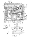
Figur 1 bei teilweise schematischer Darstellung einen Längsschnitt durch ein Hydrauliksystem undFigur 2 in vergrößertem Maßstab einen Ausschnitt der Figur1.
- Figure 1 with a partially schematic representation of a longitudinal section through a hydraulic system and
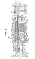
- FIG. 2 shows a detail of FIG. 1 on an enlarged scale.
Das dargestellte Hydrauliksystem 10 umfaßt ein Gehäuse 12 mit einem Sumpf 14. Eine angetriebene Pumpe 16 saugt über eine Ansaugleitung Druckmittelflüssigkeit aus dem Sumpf 14 und führt über eine Druckleitung über einen Einlaß 18 in das Gehäuse 12. Eine Gehäuseleitung 20 verbindet den Einlaß 18 mit einem rohrförmigen Mengenventil 22, das einen einstellbaren Einlaß 24 aufweist, der durch Verschwenken des Handgriffs 26 in bestimmter Weise verstellt werden kann, um die von der Gehäuseleitung 20 zu einer weiteren Gehäuseleitung 28 strömende Druckmittelmenge zu verändern. Dementsprechend liegen die Gehäuseleitung 20 bezogen auf das Mengenventil 22 stromauf und die Gehäuseleitung 28 stromab. Durch die Gehäuseleitung 28 gelangt das Druckmittel von dem Mengenventil 22 zu einem druckbeaufschlagbaren Ventilschieber 30, der in einer Bohrung 32 des Gehäuses 12 verschiebbar gelagert ist. Das eine Ende des Ventilschiebers ist dem Systemdruck P1 in der Gehäuseleitung 20 und das andere Schieberende dem Systemdruck P2 in der Gehäuseleitung 28 ausgesetzt. Der Ventilschieber 30 wird von einer Feder 36 gegen einen zylindrischen Anschlag 34 gedrückt und verstellt sich in Abhängigkeit vom Flüssigkeitsdruck in den Gehäuseleitungen 20,28, um eine gewünschte Strömung zwischen der Gehäuseleitung 28 und einem Auslaß 38 über eine ringförmige Ausdrehung 40 in der Bohrung 32 aufrechtzuerhalten, wie es in der deutschen Patentschrift 21 33 715 bzw. dem entsprechenden US-Patent 3 721 160 beschrieben ist.The
Ober die Auslaßleitung 38 gelangt das Druckmittel zu einem Auslaß 42 des Gehäuses 12 und von dort über eine Druckleitung 44 zu einem Anschluß eines verschiebbaren Steuerventils 46, das über einen zweiten Anschluß über eine Rücklaufleitung 48 mit dem Sumpf 14 verbunden ist. Das Steuerventil 46 steuert die Druckmittelverbindung von den Leitungen 44 und 48 zu den Arbeitsanschlüssen 50,52 einer Hydraulikfunktion, z.B. eines Zylinders 54. Zentrierfedern 56,58 drücken das Steuerventil 46 in seine Neutralstellung (dargestellt in Figur 1), in der Strömungsmittelfluß zum oder vom Zylinder 54 unterbunden ist. Das Steuerventil 46 läßt sich nach links und rechts durch einen Stellhebel 60 und ein nur schematisch angedeutetes Gestänge 62 in bestimmte Arbeitsstellungen verschieben, um den Zylinder 54 einzuziehen oder auszufahren.Via the
Das Hydrauliksystem 10 umfaßt ferner eine Arretiervorrichtung 64 zur automatischen und lösbaren Verriegelung des Steuerventils 46 in seinen ausgewählten Arbeitsstellungen. Die Arretiervorrichtung 64 umfaßt einen Nocken 66, der im Sumpf 14 angeordnet und mit einer Welle 68 verbunden ist, die mit dem Stellhebel 60 in Verbindung steht. Demnach wird der Nocken 66 zusammen mit dem Stellhebel 60 verschwenkt, wenn letzterer zur Verschiebung des Steuerventils in oder aus seinen ausgewählten Arbeitspositionen betätigt wird. Der Nocken 66 weist eine bogenförmige Oberfläche 70 mit zwei Vertiefungen 72,74 auf. In dem Gehäuse 12 ist ein gegenüber der genannten Oberfläche 70 hin und her verschiebbares Sperrelement 76 angeordnet, das mit einer Rolle 78 bestückt ist, die an der Nockenoberfläche 70 anliegt.The
Das Hydrauliksystem 10 umfaßt ferner eine hydromechanische Einrichtung 80, die die Arretiervorrichtung 64 kräftemäßig beaufschlagt und in Figur 2 dargestellt ist. Diese hydromechanische Einrichtung 80 umfaßt eine stufenförmige Gehäusebohrung 81 mit einem Bohrungsabschnitt 82 kleineren Durchmessers, der mit einem Bohrungsabschnitt 84 größeren Durchmessers über eine konische Ringschulter 86 verbunden ist. Das Ende des Bohrungsabschnitts 84 größeren Durchmessers ist gegenüber der Gehäuseleitung 20 offen. Ein mittlerer Abschnitt des Bohrungsabschnitts 84 ist an die Gehäuseleitung 28 angeschlossen. Das Ende des Bohrungsabschnitts 82 kleineren Durchmessers steht mit dem Sumpf 14 in Verbindung. Das Sperrelement 76 der Arretiervorrichtung 64 besteht aus einem zylindrischen Körper, der in dem Bohrungsabschnitt 82 kleineren Durchmessers verschiebbar gelagert ist. Der genannte zylindrische Körper weist mehrere öffnungen 85 auf (von denen eine in Figur 2 dargestellt ist), die sich in axialer Richtung durch den zylindrischen Körper hindurch erstrecken.The
Die hydromechanische Einrichtung 80 umfaßt ferner einen Hülseneinsatz 87 mit einer Hülse 88. Letztere besteht aus einem hohlzylindrischen Körper 89 mit einem Außendurchmesser D1 und ist in dem Bohrungsabschnitt 84 größeren Durchmessers verschiebbar gelagert. Der Hülsenkörper 89 weist in seiner äußeren Mantelfläche mehrere Ringnuten 90 und im Abstand hiervon einen Ringschlitz 91 auf, der über mehrere Radialbohrungen 92 mit dem Innenraum der Hülse 88 in Verbindung steht. Letztere umfaßt ferner ein Halsteil 84, das sich in axialer Richtung von dem Hülsenkörper 89 bis zu dem Sperrelement 76 erstreckt. Der Hülsenkörper 89 weist ein abgeschrägtes Ende 95 auf, das eine Ringkante 97 definiert, die abdichtend an der konischen Ringschulter 86 des Gehäuses 12 anliegen kann. Der Durchmesser D2 der Ringkante 97 ist kleiner als der Außendurchmesser D1 des Hülsenkörpers 89. Eine abgestufte Bohrung 96 erstreckt sich axial durch den Hülsenkörper 89 und das Halsteil 94 der Hülse 88. Diese Bohrung umfaßt einen ersten Durchmesserabschnitt 98, der sich durch das Halsteil 94 erstreckt und über eine kegelförmige Anschlagfläche 100 mit einem zweiten Durchmesserabschnitt 102 verbunden ist, der seinerseits über einen schulterförmigen Axialanschlag 104 mit einem dritten Durchmesserabschnitt 106 verbunden ist.The
Der Hülseneinsatz 87 umfaßt ferner einen Kolben 120 mit einem Kolbenboden 122 und einem zylindrischen Mantel 124, der verschiebbar und abdichtend in dem dritten Durchmesserteil 106 der Bohrung 96 der Hülse 88 geführt ist. Eine Axialbohrung 126 erstreckt sich mittig durch den Kolbenboden 122. Der Kolben 120 wird innerhalb der Hülse 88 durch eine Rückhalteeinrichtung gehalten, die in dem Ausführungsbeispiel aus einem Abdichtring 128 und einem Sprengring 130 besteht.The
Der Hülseneinsatz 87 umfaßt ferner eine Stange 140, die sich mit einem ersten Durchmesserabschnitt 142 mit der Querschnittsfläche A1 verschiebbar durch den Bohrungsabschnitt 98 der Hülse 88 erstreckt und mit seinem freien Ende am Sperrelement 76 anliegt. Ein zweiter Durchmesserabschnitt 144 der Stange 140 erstreckt sich durch die Kolbenbohrung 126 unter Freilassung eines Ringspaltes 145. Ein dritter Durchmesserabschnitt 146 der Stange 140 weist eine Querschnittsfläche A3 auf und ist verschiebbar und abdichtend in einer Führung 148 gelagert, die in dem Gehäuse 12 über einen Sprengring 150 festgelegt ist. Die Querschnittsfläche A3 ist größer als die Querschnittsfläche A1. O-Ringe 152 bilden eine Abdichtung zwischen Gehäuse 12 und Führung 148, um die Gehäuseleitung 20 gegenüber dem Sumpfdruck Ps abzudichten, dem das äußere Ende des Stangenabschnitts 146 ausgesetzt ist. Zwischen dem ersten und zweiten Durchmesserabschnitt 142,144 ist ein Flansch 141 vorgesehen, der einen Kegelsitz 143 aufweist und hiermit an der Anschlagfläche 100 der Hülse 88 anliegen kann.The
Hülse 88 und Stange 140 bilden zusammen mit der Wandung der Gehäusebohrung 81 einen ersten Hohlraum 108, der über die öffnungen 85 des Sperrelementes 76 dem Sumpfdruck (Ps) ausgesetzt ist. Der Ringraum zwischen Stange 180 und Hülse 88 definiert einen zweiten Hohlraum 110, der dem Systemdruck in den Gehäuseleitungen 20,28 über das offene Ende 112 der Hülse 88 bzw. über die Radialbohrungen 92 ausgesetzt ist. Die Stange 140 weist eine Schulter 147 auf, die gegen die Führung 148 anschlagen und so die Verschiebung der Stange 140 von dem Sperrelement 76 weg begrenzen kann.The
Durch den Kolben 120 und die Stange 140 wird der zweite Hohlraum 110 in eine erste Kammer 154 unterteilt, die über die Radialbohrungen 92 mit dem Stromab-Systemdruck P2 in der Gehäuseleitung 28 in Verbindung steht, und in eine zweite Kammer 156, die mit dem Stromauf-Systemdruck P1 in der Gehäuseleitung 20 über das offene Ende 112 der Hülse 88 in Verbindung steht. Dementsprechend sind also die Querschnittsflächen A1 und A3 an sich gegenüberliegenden Enden der Stange 140 dem Sumpfdruck Ps ausgesetzt, während der mittlere Stangenabschnitt zwischen den Stangenabschnitten 142 und 146 dem Systemdruck P1 oder P2 im zweiten Hohlraum 110 ausgesetzt ist.The
In der ersten Kammer 154 ist eine erste Feder 160 mit einer Federkonstanten K1 angeordnet und wird zusammengedrückt gehalten zwischen dem Flansch 141 der Stange 140 und dem Kolbenboden 122. Eine zweite Feder 162 mit der Federkonstanten K2, die kleiner ist als K1, ist in der zweiten Kammer 156 angeordnet und wird unter Druck gehalten zwischen dem Kolbenboden 122 und dem Abdichtring 128. Länge und Federkonstanten K1,K2 der Federn 160 und 162 sind so gewählt, daß der Kolbenboden 122 normalerweise im Abstand vom Axialanschlag 104 der Hülse 88 liegt. Eine verhältnismäßig weiche dritte Feder 164 liegt unter Vorspannung zwischen dem Abdichtring 128 und der Führung 148.A
Nachfolgend wird die Funktionsweise des Hydrauliksystems erläutert: Zuerst wird angenommen, daß die nicht dargestellte Antriebsmaschine nicht arbeitet, so daß also die Pumpe 16 nicht pumpt. Ferner wird angenommen, daß sich der Hebel 60 und damit auch das Steuerventil 46 in ihrer Neutralstellung befinden, so daß Druckmittelfluß zum und vom Zylinder 54 unterbunden ist. Daraus folgt, daß kein Druckmittel durch die Gehäuseleitungen 20,28 strömt, und daß die hier bestehenden Drücke sowie die Drücke in dem ersten Hohlraum 108 sowie in den Kammern 154,156 gleich sind und dem Sumpfdruck entsprechen. In diesem Fall befindet sich der Hülseneinsatz 87 in seiner nicht dargestellten Neutralstellung, in der beide Federn 160,162 ihre maximal mögliche Ausdehnung aufweisen und die Anschlagfläche 100 gegen den Kegelsitz 143 drücken, wodurch die Ringkante 97 im Abstand von der konischen Ringschulter 86 des Gehäuses 12 gehalten wird. Vorstehend wurde bereits ausgeführt, daß die Federn 160,162 so dimensioniert sind, daß der Kolbenboden 122 im Abstand vom Axialanschlag 104 der Hülse 88 gehalten wird. In dieser Neutralstellung werden die gesamten Kräfte der Federn 160,162 von der Hülse 88 zwischen ihre Anschlagfläche 100 und ihrem Abdichtring 128 absorbiert, so daß keine Federkraft auf das Sperrelement 76 übertragen wird. Lediglich die sehr schwach ausgelegte Feder 164 drückt das Ende des Stangenabschnitts 142 leicht gegen das Sperrelement 76, so daß diese weiche Feder 164 die einzige Kraft darstellt, mit der die Rolle 78 an der Nockenoberfläche 70 gehalten wird. Die Kraft der Feder 164 ist so klein, daß sie allein nicht ausreicht, den Stellhebel 60 und den Nocken 66 in einer Stellung festzuhalten, in der die Rolle 78 in die Vertiefung 72 oder 74 eintaucht gegen die Kraft derZentrierfedern 56,58. Bei abgeschalteter Pumpe und keinem Druckmittelfluß in den Gehäuseleitungen 20,28 werden also die Zentrierfedern 56,58 das Steuerventil 46, den Verstellhebel 60 sowie den Nocken 66 in ihre neutrale Stellung verschieben, in der die Rolle 78 aus den Vertiefungen 72,74 herausgedrückt wird.The operation of the hydraulic system is explained below: First, it is assumed that the drive machine, not shown, is not working, so that the
Unter der Annahme, daß die nicht dargestellte Antriebsmaschine eingeschaltet wird, die Pumpe 16 also zu arbeiten beginnt, sich aber der Verstellhebel 60 und das Steuerventil 46 noch in ihrer neutralen Stellung befinden, baut sich der Systemdruck in den Gehäuseleitungen 20,28 auf. Da aber kein Druckmittelfluß zum Zylinder 54 stattfindet, gibt es auch am Mengenventil 22 keinen Druckabfall, so daß der Flüssigkeitsdruck zwischen den Gehäuseleitungen 20,28 und zwischen den Kammern 154,156 stromauf und stromab vom Mengenventil 22 abgeglichen ist. Jedoch besteht eine Druckdifferenz zwischen dem Systemdruck in den Gehäuseleitungen 20,28 und dem Sumpfdruck Ps im ersten Hohlraum 108, da dieser über die öffnungen 85 dem Sumpfdruck ausgesetzt ist. Diese Druckdifferenz bewirkt eine hydraulische Vorspannung, in dem die Hülse 88 in Richtung auf den Nocken 66 in eine Vorspannungsstellung verschoben wird (dargestellt in den Figuren 1 und 2), während die Hülsenanschlagfläche 100 vom Kegelsitz 143 der Stange abgezogen wird, die Federn 160,162 zwischen Flansch 141 und Abdichtring 128 zusammengedrückt werden, und die Ringkante 97 sich dichtend an der Gehäuseringschulter 86 anlegt. Durch diese Abdichtung wird der Flüssigkeitsstrom um die äußere Mantelfläche der Hülse 88 herum unterbunden und eine weitere Druckdifferenz aufgebaut zwischen dem Hohlraum 108 und den Gehäuseleitungen 20, 28. Die Kompression der Federn 160,162 erzeugt die Vorspannungskraft, die über den Stangenflansch 141, den Stangenabschnitt 142 und das Sperrelement 76 die Rolle 78 gegen den Nocken 66 drückt. Diese Vorspannungskraft ist größer als die ursprüngliche Federkraft der Feder 164 während der vorstehend beschriebenen Neutralstellung. Diese Vorspannungskraft ergibt sich aus der Verschiebung der Hülse 88 infolge der Druckdifferenz zwischen dem Sumpf- druck Ps im Hohlraum 108 und dem höheren Systemdruck in den Gehäuseleitungen 20,28, nicht aber aus der Feder 164. Die Stange 140 unterliegt einer hydraulischen Entlastungskraft, die die Stange 140 von dem Nocken 66 abziehen will. Diese hydraulische Entlastungskraft ergibt sich aus dem Druckdifferential zwischen dem Systemdruck und dem Sumpfdruck (P1 - Ps), der die Querschnittsdifferenz zwischen den Stangenquerschnitten A3 und A1 beaufschlagt. Diese hydraulische Entlastungskraft wird wesentlich überschritten durch die vorstehend beschriebene Vorspannungskraft, so daß die Stange 140 fest gegen das Sperrelement 76 gedrückt wird. Hier ist festzustellen, daß sich die Hülse 88 ebenfalls in ihre Vorspannungsposition verschieben würde, wenn die Pumpe 16 gestartet würde, während die Bedienungsperson manuell das Steuerventil 46 in einer aktiven, Flüssigkeitsströmung zulassenden Stellung halten würde.Assuming that the prime mover, not shown, is switched on, that is, the
Nunmehr wird angenommen, daß sich der Hülseneinsatz 87 in seiner vorstehend beschriebenen Vorspannungsstellung befindet, und daß nun Verstellhebel 60, Nocken 66 und Steuerventil 46 von der Bedienungsperson in eine ihrer ausgewählten Arbeitsstellungen verschoben werden, in der das Druckmittel zum oder vom Zylinder 54 zu strömen beginnt, und in der eine der Vertiefungen 72 oder 74 so ausgerichtet ist, daß sie die Rolle 78 aufnehmen kann. In diesem Fall drückt die Vorspannungskraft sofort die Rolle 48 in Verriegelungsstellung mit einer der Vertiefungen 72 oder 74, während die Federn 160,162 sich etwas ausdehnen, weil die Rolle 78 in die Vertiefung eintaucht, wobei jedoch die Hülse 88 in ihrer Vorspannungsstellung verbleibt.Now it is assumed that the
Da sich das Steuerventil 46 in Arbeitsstellung befindet, beginnt nunmehr das Druckmittel durch die Gehäuseleitungen 20,28 zu strömen, während das Steuerventil 46 einer hydraulischen Rückstellkraft unterworfen ist, die das Steuerventil 46 in seine Neutralstellung zurückzuverschieben trachtet. Diese hydraulische Rückstellkraft nimmt mit Zunahme der Flüssigkeitsströmung ebenfalls zu. Da aber diese Flüssigkeitsströmung am Mengenventil 22 ein Druckdifferential erzeugt, ist der Stromauf-Systemdruck P1 in der Gehäuseleitung 20 höher als der Stromab-Systemdruck P2 in der Gehäuseleitung 28. Der genannte Druck P1 wird über das offene Ende 112 der Hülse 88 und die öffnung in dem Dichtring 128 auf die Kammer 156 gegeben. Der genannte Stromab-Druck P2 wird über den Ringschlitz 91 und die Radialbohrungen 92 auf die Kammer 154 gegeben. Dieser Differenzdruck (P1 - P2) zwischen den Kammern 156 und 154 erzeugt eine hydraulische Sperrkraft, in dem der Kol- ben 120 nach links verschoben wird (bezogen auf Figur 2) und dabei die Feder 160 zusammendrückt und so die auf den Flansch 141 einwirkende Kraft erhöht, die über die Stange 140 und das Sperrelement 76 die Rolle 78 innerhalb der Vertiefung 72 öder 74 festhält. Nimmt der Druckmittelfluß zu, erhöht sich auch die Druckdifferenz (P1 - P2) für eine bestimmte Einstellung des Mengenventils 22, und dementsprechend nimmt auch die hydraulische Sperrkraft zu. Diese erhöhte hydraulische Sperrkraft kompensiert die erhöhte hydraulische Ventilverstellkraft und verhindert dadurch eine Verschiebung des Steuerventils 46 in seine Neutralstellung. Es ist festzustellen, daß die Hülse 88 in ihrer Vorspannungsstellung verbleibt, nachdem das Steuerventil 46 in eine Arbeitsstellung verschoben worden ist. Bei dieser Arbeitsposition setzt sich also die Sperrkraft bzw. Verriegelungskraft zusammen aus der hydraulischen Vorspannungskraft und der hydraulischen Kolbensperrkraft. Die kombinierte Lösungskraft setzt sich zusammen aus den Kräften der Zentrierfedern, der hydraulischen Stangenlösungskraft und der hydraulischen Ventillösungskraft. In dieser Arbeitsstellung ist die kombinierte Verriegelungskraft größer als die kombinierte Lösungskraft und verhindert ein Lösen der Arretiervorrichtung 64. Außerdem werden die flüssigkeitserzeugten Verriegelungskräfte innerhalb eines Zeitintervalls aufgebaut, das kürzer ist als die Reaktionszeit der Bedienungsperson, so daß er nicht wissentlich den Stellhebel 60 in der Arbeitsstellung halten muß, während er darauf wartet, daß die hydraulischen Verriegelungskräfte einen Wert erreichen, der ausreicht, die kombinierten Lösungskräfte zu übersteigen.Since the
Falls keine anderen Begrenzungen vorgesehen wären, würde es die zunehmende hydraulische Sperrkraft für die Bedienungsperson schwierig machen, manuell die Arretiervorrichtung 64 zu übersteuern durch Verschieben des Hebels 60, des Nockens 66 und des Steuerventils 46 zurück in ihre Neutralstellungen. Erfindungsgemäß ist jedoch zur Begrenzung dieser hydraulischen Sperrkraft der Axialanschlag 104 in der Hülse 88 vorgesehen. Bewegt sich z.B. der Kolben 120 infolge des zunehmenden Druckdifferentials (P1-P2) nach links, so schlägt der Kolbenboden 122 schließlich am Axialanschlag 104 an. An dieser Stelle wird ein weiteres Zusammendrücken der Feder 160 verhindert, und die auf den Kolben 120 wirkende Kraft, die sich aus einem weiteren Anstieg des Druckdifferentials (P1 - P2) ergibt, wird auf das Gehäuse 12 übertragen und zwar durch die Anlage des Kolbenbodens 122 an der Schulter 104 und die Anlage der Hülsenringkante 97 an der Gehäuseringschulter 86. Der Axialanschlag 104 begrenzt somit die Kompression der Feder 160 und begrenzt die vorstehend beschriebene hydraulische Sperrkraft. Der Kolbenboden 122 schlägt am Axialanschlag 104 an, bevor die Feder 160 vollständig zusammengedrückt ist, so daß sich die Stange 140 nach rechts bewegen kann (bezogen auf Figur 2), so daß die Rolle 78 aus der Vertiefung 72 oder 74 während einer manuellen übersteuerung austreten kann, ohne daß auch der Kolben 120 vom Axialanschlag 104 gegen den Differenzdruck (P1 - P2) verschoben werden muß.If there were no other limitation, it would be the increasing hydraulic locking force for the operator make it difficult to manually override the
Hohe Differenzdrücke (P1 - P2) zwischen den Kammern 156 und 154 können sich ergeben, wenn das Mengenventil 22 auf kleine Strömungsmengen eingestellt ist. Der Ringspalt 145 zwischen Kolben 120 und Stangenabschnitt 144 ist vorgesehen, um ein Fressen der Stange 140 und des Kolbens 124 zu verhindern und eine minimale Druckmittelströmung auch dann zu ermöglichen, wenn das Mengenventil 22 vollständig geschlossen ist.High differential pressures (P1 - P2) between the
Es ist möglich, den von der Pumpe 16 kommenden Systemdruck zu verlieren, während sich das Steuerventil in seiner Arbeitsstellung befindet, und während Druckmittel zum oder vom Zylinder 54 strömt. Dieser Druckabfall kann sich ergeben, wenn die Antriebsmaschine aufhört zu arbeiten, während der Zylinder 54 betätigt wird. In diesem Fall verringert sich das Druckdifferential zwischen den Drücken P1 und P2, und beide Drücke P1 und P2 erreichen den Sumpfdruck Ps. Bei abnehmendem Druckdifferential (P1 - P2) bewegt sich der Kolben 120 nach rechts und erlaubt somit eine Ausdehnung der Feder 160 und dadurch eine Verminderung der hydraulischen Kolbensperrkraft. Erreichen die Drücke P1 und P2 eine vorbestimmte untere Grenze, dann reicht der System-Sumpf Differentialdruck, der auf den Durchmesser D2 der Hülse 88 einwirkt, nicht aus, um die Hülsenringkante 97 gegen die Gehäuseringschulter 86 gegen die Kraft der Federn 160 und 162 zu halten. Die Ringkante 97 bewegt sich deshalb von der Ringschulter 86 weg und erhöht dadurch den Leckstrom zwischen den Hohlräumen 110 und 108 um die äußere Mantelfläche der Hülse 88 herum. Dieser erhöhte Leckstrom führt zu einer weiteren Reduzierung des System-Sumpf Druckdifferentials und stellt sicher, daß die Hülse 88 sich weiter wegbewegt von der Gehäuseringschulter 86, so daß sich die Federn 160 und 162 weiter entspannen, bis die Hülsenanschlagfläche 100 den Kegelsitz 143 der Stange 140 berührt; an dieser Stelle wird wiederum die gesamte Kraft der Federn 160,162 aufgenommen zwischen der Hülsenanschlagfläche 100 und dem Abdichtring 128. An dieser Stelle drücken die Federn 160,162 das Ende des Stangenabschnitts 142 nicht mehr gegen das Sperrelement 76, so daß die vorstehend beschriebene Vorspannkraft aufgehoben ist. Durch die Eliminierung der Vorspannungskraft und der hydraulischen Kolbensperrkraft können die Zentrierfedern 56,58 automatisch Steuerventil 46, Hebel 60 und Nocken 66 zurück in ihre Neutralstellung verschieben, ohne daß es irgendwelcher Beachtungen seitens der Bedienungsperson bedarf. Dies verhindert eine zufällige Betätigung des Zylinders 54, falls Pumpendruck wiedergewonnen wird, wenn der Fahrer des Fahrzeugs die Fahrzeugmaschine wieder startet.It is possible to lose the system pressure coming from the
Erreicht der Zylinder 54 das Ende seines Hubes während normaler Betätigung, hört der Druckmittelfluß durch das Steuerventil 46 und durch die Gehäuseleitungen 20,28 auf, und der Druck P2 nähert sich dem Druck P1, da das Druckdifferential (P1 - P2) am Mengenventil 22 abnimmt. Dadurch wird der Kolben 120 verschoben und eine Ausdehnung der Feder 160 ermöglicht, wodurch die vorstehend beschriebene hydraulische Kolbensperrkraft begrenzt wird, so daß lediglich die Vorspannungssperrkraft verbleibt, um einer Bewegung des Nockens 66 in seine Neutralstellung entgegenzuwirken. Bei aufhörender Druckmittelströmung endet auch die hydraulische Ventillösungskraft. Da jedoch die Pumpe 16 noch arbeitet, wird die Stange 140 immer noch mit der vorstehend beschriebenen Stangenlöskraft beaufschlagt. Demgemäß setzt sich am Ende des Zylinderhubes die kombinierte Löskraft zusammen aus der Federzentrierkraft und der hydraulischen Stangenlöskraft. Diese kombinierte Löskraft ist größer als die verbleibende Vorspannungssperrkraft, so daß Hebel 60, Nocken 66 und Steuerventil 46 automatisch in ihre Neutralstellung zurückkehren und dabei die Rolle 78 aus-der Vertiefung 72 oder 74 am Ende des Kolbenhubes herausziehen.If the
Beginnt der Nocken 66 während des Lösungsvorganges zu verschwenken, so daß die Rolle 78 aus der Vertiefung 72 oder 74 herausgezogen wird, nimmt die effektive, auf die Rolle 78 wirkende Löskraft zu und zwar als Folge der Winkelveränderung des Punktes, an dem die Rolle 78 an der Nockenoberfläche 70 anliegt. Die effektive Zunahme der Löskraft ist größer als die zusätzliche Sperrkraft, die sich aus der Zusammendrückung der Federn 160,162 ergibt infolge der Bewegung der Rolle 78 aus der Vertiefung heraus. Ist also die Lösung der Verriegelung erst einmal eingeleitet, wird sie bis zur vollständigen Erreichung durchgeführt.If the
Bei rückwärts gerichteter Strömung kann sich eine Lösung zur Entriegelung dann ergeben, wenn ein zusätzlicher, nicht dargestellter Hydraulikzylinder, der geringeren Druck benötigt als der Zylinder 54, schnell betätigt wird durch ein Parallelventil, das an dieselbe Druckquelle angeschlossen ist, während das Steuerventil 46 den Zylinder 54 betätigt. Es wäre wünschenswert, wenn die Arretiervorrichtung auch bei dieser Bedingung das Steuerventil 46 in seiner Arbeitsstellung festhalten würde, so daß die Bedienungsperson das Steuerventil 46 nicht zu reaktivieren braucht, wenn die genannte Bedingung endet. Während dieser rückwärtigen Strömung kann der Systemdruck schnell abfallen und das Druckmittel kann durch das Mengenventil 22 in umgekehrter Richtung strömen und dabei ein Druckdifferential erzeugen, das den Kolben 120 vom Nocken 66 weg zu schieben trachtet und eine Ausdehnung der Feder 160 bewirkt, wodurch die hydraulische Kolbensperrkraft reduziert wird und ein Lösen der Arretiervorrichtung anstrebt. Erfindungsgemäß wird diese ungewünschte Lösung der Arretiervorrichtung verhindert durch die axiale Verlängerung des zylindrischen Teils 124 des Kolbens 120. Das Ende dieses zylindrischen Teils 124 kann gegen den Abdichtring 128 anschlagen und so die Bewegung des Kolbens-120 in einer vom Nocken 66 weggerichteten Richtung begrenzen, wodurch auch eine Ausdehnung der Feder 160 begrenzt wird. Solange also der Systemdruck während der rückwärtsgerichteten Druckmittelströmung ausreicht, die Hülse 88 gegen die Gehäuseringschulter 86 zu halten, hält die begrenzte Ausdehnung der Feder 160 zumindest eine vorbestimmte Verriegelungskraft aufrecht, um ein Lösen der Arretiervorrichtung während dieser Rückwärtsströmung zu verhindern.In the case of a backward flow, an unlocking solution can result if an additional hydraulic cylinder, not shown, which requires less pressure than the
Claims (21)
gekennzeichnet durch folgende Merkmale:
characterized by the following features:
Priority Applications (1)
| Application Number | Priority Date | Filing Date | Title |
|---|---|---|---|
| AT81108401T ATE9027T1 (en) | 1980-11-03 | 1981-10-16 | HYDRAULIC SYSTEM WITH A HYDROMECHANICAL LOCKING DEVICE FOR THE WORKING POSITION OF A CONTROL VALVE. |
Applications Claiming Priority (2)
| Application Number | Priority Date | Filing Date | Title |
|---|---|---|---|
| US06/203,300 US4339987A (en) | 1980-11-03 | 1980-11-03 | Pressure detent mechanism |
| US203300 | 1980-11-03 |
Publications (2)
| Publication Number | Publication Date |
|---|---|
| EP0051186A1 true EP0051186A1 (en) | 1982-05-12 |
| EP0051186B1 EP0051186B1 (en) | 1984-08-15 |
Family
ID=22753376
Family Applications (1)
| Application Number | Title | Priority Date | Filing Date |
|---|---|---|---|
| EP19810108401 Expired EP0051186B1 (en) | 1980-11-03 | 1981-10-16 | Hydraulic system comprising a locking device for maintaining a control valve in its working position |
Country Status (11)
| Country | Link |
|---|---|
| US (1) | US4339987A (en) |
| EP (1) | EP0051186B1 (en) |
| JP (1) | JPS57107406A (en) |
| AT (1) | ATE9027T1 (en) |
| AU (1) | AU542526B2 (en) |
| BR (1) | BR8107079A (en) |
| CA (1) | CA1158960A (en) |
| DE (1) | DE3165575D1 (en) |
| DK (1) | DK156520C (en) |
| ES (1) | ES8206777A1 (en) |
| ZA (1) | ZA817567B (en) |
Cited By (4)
| Publication number | Priority date | Publication date | Assignee | Title |
|---|---|---|---|---|
| EP0331176A1 (en) * | 1988-03-03 | 1989-09-06 | KABUSHIKI KAISHA KOBE SEIKO SHO also known as Kobe Steel Ltd. | Detent device for a control lever |
| EP0368322A2 (en) * | 1988-11-11 | 1990-05-16 | KABUSHIKI KAISHA KOBE SEIKO SHO also known as Kobe Steel Ltd. | Control lever apparatus and actuator operation apparatus |
| US5156065A (en) * | 1988-11-11 | 1992-10-20 | Kabushiki Kaisha Kobe Seiko Sho | Control lever apparatus and actuator operation apparatus |
| FR2684776A1 (en) * | 1991-12-09 | 1993-06-11 | Caterpillar Inc | CARTRIDGE RETAINING MECHANISM, IN PARTICULAR FOR A FLUID REGULATOR VALVE. |
Families Citing this family (3)
| Publication number | Priority date | Publication date | Assignee | Title |
|---|---|---|---|---|
| US4530376A (en) * | 1983-09-19 | 1985-07-23 | Dresser Industries, Inc. | Pilot valve including a hydraulically actuated detent |
| US4913190A (en) * | 1989-04-24 | 1990-04-03 | Deere & Company | Detent mechanism for a control valve |
| US6976504B2 (en) * | 2003-04-18 | 2005-12-20 | Sauer-Danfoss Inc. | Selectable detent relief valve |
Citations (6)
| Publication number | Priority date | Publication date | Assignee | Title |
|---|---|---|---|---|
| US2276979A (en) * | 1938-12-01 | 1942-03-17 | American Lurgi Corp | Apparatus for locking control plungers in slide valve control devices |
| US2689585A (en) * | 1952-06-23 | 1954-09-21 | Bendix Aviat Corp | Self-holding valve |
| US3511276A (en) * | 1968-04-04 | 1970-05-12 | Caterpillar Tractor Co | Fluid control valve with conditional self-actuating means |
| US3650297A (en) * | 1970-09-30 | 1972-03-21 | Webster Electric Co Inc | Spool release and sequence valve |
| US3837359A (en) * | 1973-05-18 | 1974-09-24 | Int Harvester Co | Hydraulic control valve with pressure sensitive latch |
| US3866880A (en) * | 1973-10-09 | 1975-02-18 | Caterpillar Tractor Co | Valve assembly having a pressure responsive detent mechanism |
Family Cites Families (10)
| Publication number | Priority date | Publication date | Assignee | Title |
|---|---|---|---|---|
| US2610613A (en) * | 1947-12-23 | 1952-09-16 | Air Hydraulies Inc | Air operated impact press |
| US2759456A (en) * | 1954-04-12 | 1956-08-21 | Vickers Inc | Power transmission |
| US2844166A (en) * | 1954-11-03 | 1958-07-22 | Deere Mfg Co | Hydraulic detent for valve |
| US3106065A (en) * | 1961-02-13 | 1963-10-08 | Parker Hannifin Corp | Position hold and release mechanisms for flow control valves |
| US3670628A (en) * | 1970-09-02 | 1972-06-20 | Caterpillar Tractor Co | Kickout valve and circuit |
| US3721160A (en) * | 1970-10-26 | 1973-03-20 | Deere & Co | Hydro-mechanical detent mechanism |
| US3776099A (en) * | 1971-12-06 | 1973-12-04 | Applied Power Inc | Automatic release and centering device |
| US3972264A (en) * | 1973-09-04 | 1976-08-03 | Caterpillar Tractor Co. | Hydraulically actuated detent mechanism |
| US3980336A (en) * | 1974-06-26 | 1976-09-14 | Ross Operating Valve Company | Safety valve for tailgates or the like |
| GB1590581A (en) * | 1976-10-14 | 1981-06-03 | Hawker Siddeley Dynamics Eng | Electro-hydraulic systems |
-
1980
- 1980-11-03 US US06/203,300 patent/US4339987A/en not_active Expired - Lifetime
-
1981
- 1981-09-11 CA CA000385722A patent/CA1158960A/en not_active Expired
- 1981-10-14 AU AU76314/81A patent/AU542526B2/en not_active Ceased
- 1981-10-16 AT AT81108401T patent/ATE9027T1/en not_active IP Right Cessation
- 1981-10-16 EP EP19810108401 patent/EP0051186B1/en not_active Expired
- 1981-10-16 DE DE8181108401T patent/DE3165575D1/en not_active Expired
- 1981-10-30 BR BR8107079A patent/BR8107079A/en unknown
- 1981-11-02 ZA ZA817567A patent/ZA817567B/en unknown
- 1981-11-02 ES ES506770A patent/ES8206777A1/en not_active Expired
- 1981-11-02 JP JP17631881A patent/JPS57107406A/en active Pending
- 1981-11-03 DK DK484881A patent/DK156520C/en not_active IP Right Cessation
Patent Citations (6)
| Publication number | Priority date | Publication date | Assignee | Title |
|---|---|---|---|---|
| US2276979A (en) * | 1938-12-01 | 1942-03-17 | American Lurgi Corp | Apparatus for locking control plungers in slide valve control devices |
| US2689585A (en) * | 1952-06-23 | 1954-09-21 | Bendix Aviat Corp | Self-holding valve |
| US3511276A (en) * | 1968-04-04 | 1970-05-12 | Caterpillar Tractor Co | Fluid control valve with conditional self-actuating means |
| US3650297A (en) * | 1970-09-30 | 1972-03-21 | Webster Electric Co Inc | Spool release and sequence valve |
| US3837359A (en) * | 1973-05-18 | 1974-09-24 | Int Harvester Co | Hydraulic control valve with pressure sensitive latch |
| US3866880A (en) * | 1973-10-09 | 1975-02-18 | Caterpillar Tractor Co | Valve assembly having a pressure responsive detent mechanism |
Cited By (6)
| Publication number | Priority date | Publication date | Assignee | Title |
|---|---|---|---|---|
| EP0331176A1 (en) * | 1988-03-03 | 1989-09-06 | KABUSHIKI KAISHA KOBE SEIKO SHO also known as Kobe Steel Ltd. | Detent device for a control lever |
| EP0368322A2 (en) * | 1988-11-11 | 1990-05-16 | KABUSHIKI KAISHA KOBE SEIKO SHO also known as Kobe Steel Ltd. | Control lever apparatus and actuator operation apparatus |
| EP0368322A3 (en) * | 1988-11-11 | 1991-01-02 | KABUSHIKI KAISHA KOBE SEIKO SHO also known as Kobe Steel Ltd. | Control lever apparatus and actuator operation apparatus |
| US5058451A (en) * | 1988-11-11 | 1991-10-22 | Kabushiki Kaisha Kobe Seiko Sho | Control lever apparatus and actuator operation apparatus |
| US5156065A (en) * | 1988-11-11 | 1992-10-20 | Kabushiki Kaisha Kobe Seiko Sho | Control lever apparatus and actuator operation apparatus |
| FR2684776A1 (en) * | 1991-12-09 | 1993-06-11 | Caterpillar Inc | CARTRIDGE RETAINING MECHANISM, IN PARTICULAR FOR A FLUID REGULATOR VALVE. |
Also Published As
| Publication number | Publication date |
|---|---|
| DK156520C (en) | 1990-02-12 |
| CA1158960A (en) | 1983-12-20 |
| BR8107079A (en) | 1982-07-20 |
| JPS57107406A (en) | 1982-07-03 |
| ES506770A0 (en) | 1982-08-16 |
| AU542526B2 (en) | 1985-02-21 |
| EP0051186B1 (en) | 1984-08-15 |
| DK156520B (en) | 1989-09-04 |
| ZA817567B (en) | 1983-06-29 |
| DE3165575D1 (en) | 1984-09-20 |
| DK484881A (en) | 1982-05-04 |
| ES8206777A1 (en) | 1982-08-16 |
| US4339987A (en) | 1982-07-20 |
| AU7631481A (en) | 1982-05-13 |
| ATE9027T1 (en) | 1984-09-15 |
Similar Documents
| Publication | Publication Date | Title |
|---|---|---|
| DE2405699A1 (en) | HYDRAULIC CONTROL VALVE | |
| DE3630823C2 (en) | Hydraulic control device | |
| DE2934136C2 (en) | Throttle valve for an automatic transmission of a motor vehicle | |
| EP0051186B1 (en) | Hydraulic system comprising a locking device for maintaining a control valve in its working position | |
| EP0130306B1 (en) | Method and device for controlling a pipe isolator | |
| DE2843592C3 (en) | Power steering gear | |
| DE2447532A1 (en) | THROTTLE VALVE | |
| DE3105284A1 (en) | DELAY DETECTION VALVE | |
| DE4237932C2 (en) | Volume flow control for automotive hydraulics, in particular for steering devices of motor vehicles | |
| DE3037485A1 (en) | MAIN BRAKE CYLINDER | |
| DE3836344C2 (en) | ||
| DE2737300C2 (en) | ||
| DE2419538A1 (en) | FLUID PRESSURE SYSTEM FOR MOTOR VEHICLES | |
| DE2947651C2 (en) | Device for position feedback of the control sleeve of a control valve of a hydraulic machine | |
| EP0059968A1 (en) | Control for a hydraulic clutch | |
| DE2362348A1 (en) | SERVO ARRANGEMENT | |
| DE2718098B2 (en) | Hydraulic system for a motor vehicle | |
| DE3820539C2 (en) | ||
| DE19642567C1 (en) | Combined hydraulic valve with switching and pressure reduction functions e.g. for holding brake | |
| DE2736095B2 (en) | Control valve for a hydraulic vehicle brake system | |
| DE19834193C1 (en) | Master cylinder for hydraulic motor vehicle brake | |
| DE2401101C3 (en) | Control slide device for gradually increasing the fluid pressure in a hydraulic control line for a gearshift transmission | |
| DE2318915C2 (en) | Sequence control device for a hydrostatic displacement machine adjustable on one side | |
| DE102022131012B3 (en) | AUTOMATIC OIL RETURN STRUCTURE FOR PISTON PUMPS | |
| DE2448524A1 (en) | HYDRAULIC CONTROL FOR ONE HYDRAULIC MOTOR TO BE OPERATED IN TWO PRESSURE LEVELS |
Legal Events
| Date | Code | Title | Description |
|---|---|---|---|
| PUAI | Public reference made under article 153(3) epc to a published international application that has entered the european phase |
Free format text: ORIGINAL CODE: 0009012 |
|
| AK | Designated contracting states |
Designated state(s): AT DE FR GB IT SE |
|
| ITCL | It: translation for ep claims filed |
Representative=s name: LENZI & C. |
|
| 17P | Request for examination filed |
Effective date: 19820423 |
|
| ITF | It: translation for a ep patent filed |
Owner name: LENZI & C. |
|
| GRAA | (expected) grant |
Free format text: ORIGINAL CODE: 0009210 |
|
| AK | Designated contracting states |
Designated state(s): AT DE FR GB IT SE |
|
| REF | Corresponds to: |
Ref document number: 9027 Country of ref document: AT Date of ref document: 19840915 Kind code of ref document: T |
|
| REF | Corresponds to: |
Ref document number: 3165575 Country of ref document: DE Date of ref document: 19840920 |
|
| ET | Fr: translation filed | ||
| PLBE | No opposition filed within time limit |
Free format text: ORIGINAL CODE: 0009261 |
|
| STAA | Information on the status of an ep patent application or granted ep patent |
Free format text: STATUS: NO OPPOSITION FILED WITHIN TIME LIMIT |
|
| 26N | No opposition filed | ||
| PGFP | Annual fee paid to national office [announced via postgrant information from national office to epo] |
Ref country code: AT Payment date: 19891004 Year of fee payment: 9 |
|
| PG25 | Lapsed in a contracting state [announced via postgrant information from national office to epo] |
Ref country code: AT Effective date: 19901016 |
|
| ITTA | It: last paid annual fee | ||
| EAL | Se: european patent in force in sweden |
Ref document number: 81108401.1 |
|
| PGFP | Annual fee paid to national office [announced via postgrant information from national office to epo] |
Ref country code: GB Payment date: 19950919 Year of fee payment: 15 |
|
| PGFP | Annual fee paid to national office [announced via postgrant information from national office to epo] |
Ref country code: FR Payment date: 19951018 Year of fee payment: 15 |
|
| PGFP | Annual fee paid to national office [announced via postgrant information from national office to epo] |
Ref country code: SE Payment date: 19951025 Year of fee payment: 15 |
|
| PGFP | Annual fee paid to national office [announced via postgrant information from national office to epo] |
Ref country code: DE Payment date: 19951122 Year of fee payment: 15 |
|
| PG25 | Lapsed in a contracting state [announced via postgrant information from national office to epo] |
Ref country code: GB Effective date: 19961016 |
|
| PG25 | Lapsed in a contracting state [announced via postgrant information from national office to epo] |
Ref country code: SE Effective date: 19961017 |
|
| GBPC | Gb: european patent ceased through non-payment of renewal fee |
Effective date: 19961016 |
|
| PG25 | Lapsed in a contracting state [announced via postgrant information from national office to epo] |
Ref country code: FR Effective date: 19970630 |
|
| PG25 | Lapsed in a contracting state [announced via postgrant information from national office to epo] |
Ref country code: DE Effective date: 19970701 |
|
| EUG | Se: european patent has lapsed |
Ref document number: 81108401.1 |
|
| REG | Reference to a national code |
Ref country code: FR Ref legal event code: ST |