EP0051069B1 - Dispositif de recuperation de chaleur - Google Patents
Dispositif de recuperation de chaleur Download PDFInfo
- Publication number
- EP0051069B1 EP0051069B1 EP81901115A EP81901115A EP0051069B1 EP 0051069 B1 EP0051069 B1 EP 0051069B1 EP 81901115 A EP81901115 A EP 81901115A EP 81901115 A EP81901115 A EP 81901115A EP 0051069 B1 EP0051069 B1 EP 0051069B1
- Authority
- EP
- European Patent Office
- Prior art keywords
- container
- heat
- water
- condenser
- set forth
- Prior art date
- Legal status (The legal status is an assumption and is not a legal conclusion. Google has not performed a legal analysis and makes no representation as to the accuracy of the status listed.)
- Expired
Links
- 238000011084 recovery Methods 0.000 title claims abstract description 10
- XLYOFNOQVPJJNP-UHFFFAOYSA-N water Substances O XLYOFNOQVPJJNP-UHFFFAOYSA-N 0.000 claims abstract description 76
- 239000006200 vaporizer Substances 0.000 claims abstract description 5
- 238000010438 heat treatment Methods 0.000 claims description 16
- 239000007788 liquid Substances 0.000 claims description 16
- 239000002023 wood Substances 0.000 claims description 2
- 238000005485 electric heating Methods 0.000 claims 1
- 238000000926 separation method Methods 0.000 abstract description 2
- 238000007664 blowing Methods 0.000 description 2
- 238000005265 energy consumption Methods 0.000 description 2
- 238000000034 method Methods 0.000 description 2
- 230000015572 biosynthetic process Effects 0.000 description 1
- 239000012530 fluid Substances 0.000 description 1
- 238000009434 installation Methods 0.000 description 1
- 238000013021 overheating Methods 0.000 description 1
Images

Classifications
-
- F—MECHANICAL ENGINEERING; LIGHTING; HEATING; WEAPONS; BLASTING
- F24—HEATING; RANGES; VENTILATING
- F24D—DOMESTIC- OR SPACE-HEATING SYSTEMS, e.g. CENTRAL HEATING SYSTEMS; DOMESTIC HOT-WATER SUPPLY SYSTEMS; ELEMENTS OR COMPONENTS THEREFOR
- F24D17/00—Domestic hot-water supply systems
- F24D17/02—Domestic hot-water supply systems using heat pumps
-
- F—MECHANICAL ENGINEERING; LIGHTING; HEATING; WEAPONS; BLASTING
- F24—HEATING; RANGES; VENTILATING
- F24H—FLUID HEATERS, e.g. WATER OR AIR HEATERS, HAVING HEAT-GENERATING MEANS, e.g. HEAT PUMPS, IN GENERAL
- F24H4/00—Fluid heaters characterised by the use of heat pumps
- F24H4/02—Water heaters
- F24H4/04—Storage heaters
Definitions
- the present invention relates to a device for recovery of heat in a building, comprising a compressor driven heat pump, the vaporizer of which is adapted to receive heat from the exhaust air of the building, and the condenser of which is situated in a container, a liquid circulation circuit being arranged to recover heat from the container into the building via at least one liquid circulation element.
- Such a device is known from FR-A-2 412 791 which describes a system having a liquid container, in which the heat pump condenser is located, as well as a separated consumption hot-water container, which is coupled to the liquid container through conduits. Heat is transferred from the liquid container into the building via liquid circulation elements, e.g. radiators, on the one hand, and to the water in the consumption hot-water container, on the other hand.
- liquid circulation elements e.g. radiators
- this known system is rather complicated because of the two different water containers, and it is also difficult to control the heat transfer in such a way that priority is given to the consumption hot-water when large volumes of hot-water is temporarily consumed.
- the object of the invention is to solve this problem and to enable a controlled distribution of the recovered heat while securing that the heat pump operates with maximum efficiency.
- a liquid circulation circuit is adapted to pick up heat adjacent to the heat pump condenser in the lower part of the container and to transfer heat to the building via one or more liquid circulation elements, e.g. radiators, a circulation pump being adapted to operate intermittently in response to the water temperature in said lower part of the container so as to maintain in a relatively low water temperature in said lower part and a higher water temperature in the upper part of the container.
- the condenser temperature will be kept relatively low, resulting in high efficiency of the heat pump.
- the heat will be primarily transferred to the consumption hot water, whereas only excess heat is delivered to the building via the liquid circulation elements (e.g. radiators).
- a consumption hot-water container having a heat pump condenser in the lower part thereof is known from DE-A-2 714 618.
- heat is transferred from a refrigerator to the consumption hot-water while excess heat is discharged by blowing air along the outside of the container wall.
- the purpose of blowing air along the outside of the container wall is merely to avoid over-heating in the container and to ensure proper operation of refrigerator.
- the present invention provides for heat recovery from the exhaust air, via the hot-water container, and back to the building, resulting in a considerable saving of both installation and operational costs.
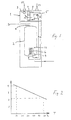
- Fig. 1 illustrates a previously known device comprising a heat pump 1 and a container 2 for consumption hot water.
- the heat pump transfers heat from a heat source, namely from the exhaust air from a building, to the water in the container 2.
- the exhaust air is drawn (arrow P1, temperature e.g. 22°C) by means of a fan 3 passed the evaporator 4 of the heat pump (arrow P2), so that the outflowing air (arrow P3) leaves the device at a substantially lower temperature, e.g. 5°C.
- the heat carrying medium is pumped to a condenser 6 located in the lower part of the hot-water container 2, from which heat is transferred to the ambient water. From the condenser 6, the heat carrying medium is returned via throttle 7 to the evaporator 4.
- Hot water is discharged via a connection 8 located in the upper part of the container 2, whereas cold water is supplied via a lower connection 9.
- a temperature sensor 10 controls the compressor 5 of the heat pump so that the water temperature in the container 2 is kept at a desired level, e.g. 55°C.
- the efficiency of the heat pump strongly depends on the temperature difference between the condenser 6 and the vaporizer 4.
- the functional relation between the efficiency factor s and the condenser temperature T (for a given temperature of the vaporizer 4) is shown in Fig. 2.
- the efficiency factor is about 2 in the above-mentioned example, i.e. at a condenser temperature of about 55°C, while the efficiency factor can be doubled, i.e. to about 4, in case the condenser 6 can be brought to work at a temperature of about 10°C. Even a moderate temperature reduction could, however, result in a substantial improvement, since the relation is essentially linear.
- the efficiency factor of the heat pump can be maintained above 3, which in a typically single-family house corresponds to an energy saving of about 40%, provided that the hot-water consumption and the heat delivered by the fluid circulation circuit (via e.g. a water radiator or a supply air device) altogether amount to about 60% of the total heat energy consumption.
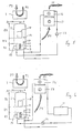
- FIG. 4 A first embodiment of the inventive heat recovery device is shown in Fig. 4. Corresponding parts are given the same reference numerals as in Fig. 3. However, there is an essential difference in that both connections of the water circulation circuit 11, 12 are located in the lower part of the hot-water container 2 adjacent to the heat pump condenser 6. Thus, the feed conduit connection 14 is disposed near, namely somewhat below, the upper edge of the condenser 6, whereas the return conduit connection, which is joined to the supply connection 9 for cold water, is located near, namely somewhat below, the lower edge of the condenser 6. Moreover, the system is controlled by two temperature sensors, namely a first temperature sensor 10, which corresponds to the sensor 10 in the prior art embodiment shown in Fig.
- connection 14 and 9 are situated in the region of the condenser 6, the latter can be kept at an advantageously low temperature level, resulting in an improved efficiency of the heat pump as discussed above.
- the return conduit connection 9 is also provided with a deflecting plate which secures that the incoming water does not flow upwards, but only sideways.
- a zone Z1 having a relatively low temperature can be maintained, whereas in the upper part of the container there remains a zone Z2 with warmer water (having a lower density). Thanks to such a temperature distribution in the container 2, it is possible to accomplish an improved efficiency of the heat pump, while preserving the desired hot-water temperature (at the discharge connection 8).
- Fig. 5 there is shown a second embodiment of the inventive heat recovery device, and corresponding parts are given the same reference numerals as in Figs. 1, 3 and 4.
- the circulation circuit contains a supply air unit having a hot-water element 16, e.g. a heating element with flanges, and a fan 17 which causes the supply air to the building to pass the element 16 and thereby be preheated, at least up to 15-20°C (depending on the temperature of the outdoor air), before being blown into the interior of the building.
- a hot-water element 16 e.g. a heating element with flanges
- a fan 17 which causes the supply air to the building to pass the element 16 and thereby be preheated, at least up to 15-20°C (depending on the temperature of the outdoor air), before being blown into the interior of the building.
- the supply air flow is schematically indicated by arrows P4 and P5.
- electrical additional heating elements 18 are arranged in the upper part of the container 2, i.e. in the upper zone Z2, electrical additional heating elements 18 are arranged. These elements 18 are controlled by an adjacent third temperature sensor 19, which turns on the elements 18 as soon as the water temperature in zone Z2 falls somewhat below the desired hot-water temperature, e.g. at a temperature of 40-90°C, particularly about 65°C.
- the temperature sensor 10, controlling the compressor of the heat pump 1 is in this case located in an intermediate zone Z3 between the upper and lower zones Z2 and Z1.
- the heat pump operates as long as the water temperature at the sensor 10 does not exceed the desired hot water temperature, namely at a temperature of e.g. 40-60°C; in particular about 55°C.
- the senor 15 can preferably control the fan 17 (instead of the pump 12, which can work continuously) so that the supply air is delivered as long as the sensed water temperature and thus approximately the temperature of the heating element 16 does not fall below 5-15°C, particularly about 10°C.
- Fig. 6 operates substantially in the same way as in Fig. 5.
- a water radiator 11 (compare Fig. 4) is connected in the water circulation circuit between the pump 12 and the heating element 16.
- the excess heat is transferred from the container 2 to the supply air (P4, P5) as well as to the air (via the radiator 11).
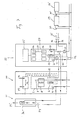
- FIG. 7 A further application of the invention is schematically shown in Fig. 7, wherein the units 20 and 21 together correspond to the embodiment according to Fig. 5.
- the water circulation circuit from the feed conduit connection 14 to .the return conduit connection 9 in the lower part of the container 2 comprises a supply air unit 21.
- this circulation circuit is also provided with a heat exchanger loop 23 disposed in the lower part of a central heating unit 22.
- This unit comprises a central heating vessel 24 and an expansion vessel 25 connected thereto.
- electrical heating elements 26 are arranged in the vessel 24 for heating the water, if necessary.
- From an upper feed conduit connection 27 the water circulates in the building (by means of a pump 28) in a loop comprising radiators 29, 29', etc.
- a shunt 32 can be arranged in conventional manner in the radiator loop.
- the water in the vessel 24 can be heated in three different ways, simultaneously or separately, namely via the heat pump 1 and the hot-water container 2, by means of the electrical elements 26 or by means of the non-illustrated heating device and the circulation circuit 33, 34, 35,36,37.
- the recirculation circuit from the hot-water container may e.g. contain some other medium than water, in which case an exchanger loop is arranged instead of the open connections 9 and 14.
- an exchanger loop is arranged instead of the open connections 9 and 14.
- the essential point is that the heat exchange is effected in the lower part of the container 2 in the region of the condensor 6 of the heat pump, so that the described temperature distribution can be maintained in the container 2.
Landscapes
- Engineering & Computer Science (AREA)
- Physics & Mathematics (AREA)
- Thermal Sciences (AREA)
- Chemical & Material Sciences (AREA)
- Combustion & Propulsion (AREA)
- Mechanical Engineering (AREA)
- General Engineering & Computer Science (AREA)
- Steam Or Hot-Water Central Heating Systems (AREA)
- Central Heating Systems (AREA)
- Heat-Pump Type And Storage Water Heaters (AREA)
- Yarns And Mechanical Finishing Of Yarns Or Ropes (AREA)
- Compression-Type Refrigeration Machines With Reversible Cycles (AREA)
Abstract
Claims (9)
Priority Applications (1)
| Application Number | Priority Date | Filing Date | Title |
|---|---|---|---|
| AT81901115T ATE16418T1 (de) | 1980-04-30 | 1981-04-24 | Vorrichtung zur rueckgewinnung von waerme. |
Applications Claiming Priority (2)
| Application Number | Priority Date | Filing Date | Title |
|---|---|---|---|
| SE8003303A SE435959B (sv) | 1980-04-30 | 1980-04-30 | Anordning for vermeatervinning |
| SE8003303 | 1980-04-30 |
Publications (2)
| Publication Number | Publication Date |
|---|---|
| EP0051069A1 EP0051069A1 (fr) | 1982-05-12 |
| EP0051069B1 true EP0051069B1 (fr) | 1985-11-06 |
Family
ID=20340889
Family Applications (1)
| Application Number | Title | Priority Date | Filing Date |
|---|---|---|---|
| EP81901115A Expired EP0051069B1 (fr) | 1980-04-30 | 1981-04-24 | Dispositif de recuperation de chaleur |
Country Status (7)
| Country | Link |
|---|---|
| US (1) | US4416121A (fr) |
| EP (1) | EP0051069B1 (fr) |
| DK (1) | DK155466C (fr) |
| FI (1) | FI72381C (fr) |
| NO (1) | NO153347C (fr) |
| SE (1) | SE435959B (fr) |
| WO (1) | WO1981003219A1 (fr) |
Families Citing this family (6)
| Publication number | Priority date | Publication date | Assignee | Title |
|---|---|---|---|---|
| US4645908A (en) * | 1984-07-27 | 1987-02-24 | Uhr Corporation | Residential heating, cooling and energy management system |
| CA2121794A1 (fr) * | 1991-10-30 | 1993-05-13 | Theodore C. Gilles | Thermopompe auxiliaire destinee a produire de l'eau chaude pour usage domestique |
| US5984198A (en) * | 1997-06-09 | 1999-11-16 | Lennox Manufacturing Inc. | Heat pump apparatus for heating liquid |
| US6739142B2 (en) | 2000-12-04 | 2004-05-25 | Amos Korin | Membrane desiccation heat pump |
| US9605882B2 (en) | 2013-12-11 | 2017-03-28 | Trane International Inc. | Heat pump with exhaust heat reclaim |
| EP4527736A1 (fr) * | 2023-09-19 | 2025-03-26 | B/E Aerospace, Inc. | Système de gestion de chaleur de cuisine de bord |
Family Cites Families (19)
| Publication number | Priority date | Publication date | Assignee | Title |
|---|---|---|---|---|
| SE190948C1 (fr) * | 1964-01-01 | |||
| US1935281A (en) * | 1931-06-03 | 1933-11-14 | Reed Frank Maynard | Heat-exchange mechanism |
| US2575325A (en) * | 1948-02-14 | 1951-11-20 | American Gas And Electric Comp | Heat pump system |
| DK133520B (da) * | 1973-10-24 | 1976-05-31 | Henning Brinch Madsen | Varmepumpeanlæg. |
| SE389188B (sv) * | 1973-12-20 | 1976-10-25 | Projectus Ind Produkter Ab | Forfarande och anordning for vermning av fluider i olika kretsar for skilda foremal medelst en vermepump, innefattande en koldmediekrets med en expansionsventil, en forangare, en kompressor och ett kondensorapparat |
| SE394741B (sv) * | 1974-04-18 | 1977-07-04 | Projectus Ind Produkter Ab | Vermepumpsystem |
| SE392766B (sv) * | 1974-04-18 | 1977-04-18 | Projectus Ind Produkter Ab | Vermeanleggning, innefattande en vermepump och en brensleeldad vermepanna med en radiatorkrets |
| DE2530994A1 (de) * | 1975-07-11 | 1977-01-27 | Licentia Gmbh | Verfahren und anlage zur nutzung der bei der kaelteerzeugung im haushalt anfallenden abwaerme |
| DE2558227A1 (de) * | 1975-12-23 | 1977-07-07 | Metro Specialfabrik For Elektr | Elektrischer boiler mit waermepumpe |
| DE2619744C2 (de) * | 1976-05-05 | 1982-05-19 | Robert Bosch Gmbh, 7000 Stuttgart | Anlage zum Beheizen eines Gebäudes und zur Warmwasserbereitung |
| US4098092A (en) * | 1976-12-09 | 1978-07-04 | Singh Kanwal N | Heating system with water heater recovery |
| US4315597A (en) * | 1977-05-02 | 1982-02-16 | Garraffa Jr Jerome | Water pre-heater of a refrigeration system |
| NL7707915A (nl) * | 1977-07-15 | 1979-01-17 | Patlico Rights Nv | Warmteopslag- en afgifte-inrichting voor warmte uit een door de zon verwarmd fluidum. |
| FR2412791A1 (fr) * | 1977-12-22 | 1979-07-20 | Must En Grpt Interet Econom | Satellite de commande pour pompe a chaleur |
| US4179894A (en) * | 1977-12-28 | 1979-12-25 | Wylain, Inc. | Dual source heat pump |
| US4246764A (en) * | 1979-02-16 | 1981-01-27 | Jimis Papadakos | Water and energy conservation system for food serving establishments |
| US4293323A (en) * | 1979-08-30 | 1981-10-06 | Frederick Cohen | Waste heat energy recovery system |
| US4336692A (en) * | 1980-04-16 | 1982-06-29 | Atlantic Richfield Company | Dual source heat pump |
| DE3027609C2 (de) * | 1980-07-21 | 1983-08-11 | BFO Blechverarbeitung und Fördertechnik Oberhessen GmbH Kesselwerk & Co KG, 6424 Grebenhain | Heizungsanordnung |
-
1980
- 1980-04-30 SE SE8003303A patent/SE435959B/sv not_active IP Right Cessation
-
1981
- 1981-04-24 EP EP81901115A patent/EP0051069B1/fr not_active Expired
- 1981-04-24 US US06/324,353 patent/US4416121A/en not_active Expired - Fee Related
- 1981-04-24 WO PCT/SE1981/000126 patent/WO1981003219A1/fr not_active Ceased
- 1981-10-29 FI FI813397A patent/FI72381C/fi not_active IP Right Cessation
- 1981-12-09 NO NO814190A patent/NO153347C/no unknown
- 1981-12-18 DK DK563781A patent/DK155466C/da not_active IP Right Cessation
Also Published As
| Publication number | Publication date |
|---|---|
| DK563781A (da) | 1981-12-18 |
| US4416121A (en) | 1983-11-22 |
| NO153347B (no) | 1985-11-18 |
| FI72381B (fi) | 1987-01-30 |
| FI813397L (fi) | 1981-10-31 |
| SE8003303L (sv) | 1981-10-31 |
| NO153347C (no) | 1986-02-26 |
| DK155466C (da) | 1989-10-16 |
| SE435959B (sv) | 1984-10-29 |
| FI72381C (fi) | 1987-05-11 |
| EP0051069A1 (fr) | 1982-05-12 |
| NO814190L (no) | 1981-12-09 |
| DK155466B (da) | 1989-04-10 |
| WO1981003219A1 (fr) | 1981-11-12 |
Similar Documents
| Publication | Publication Date | Title |
|---|---|---|
| US4241588A (en) | Energy conserving water heating system | |
| US4438881A (en) | Solar assisted heat pump heating system | |
| US4378787A (en) | Solar heating system | |
| US4111259A (en) | Energy conservation system | |
| US8141623B2 (en) | Automatic switching two pipe hydronic system | |
| US5366153A (en) | Heat pump system with refrigerant isolation and heat storage | |
| US4143642A (en) | High temperature thermal storage system utilizing solar energy units | |
| US4738305A (en) | Air conditioner and heat dispenser | |
| US20060218949A1 (en) | Water-cooled air conditioning system using condenser water regeneration for precise air reheat in dehumidifying mode | |
| GB2247072A (en) | Heating or cooling system | |
| CA2092879A1 (fr) | Echangeur de chaleur pour reservoir d'eau chaude | |
| US5806331A (en) | Water-based hot water heat pump | |
| US20250043962A1 (en) | Heating installation | |
| US4754614A (en) | Prime-motor-driven room warming/cooling and hot water supplying apparatus | |
| EP2657619B1 (fr) | Procédé et dispositif de contrôle d'un système de chauffage et ventilation hybride | |
| EP0051069B1 (fr) | Dispositif de recuperation de chaleur | |
| US4378785A (en) | Solar heating system | |
| US4368624A (en) | Absorption type heat pump having indoor and outdoor radiators connected in series in a water flow circuit during heat mode | |
| EP0772754B1 (fr) | Procede et transfert d'energie de chauffage et/ou de refroidissement | |
| US4604991A (en) | Hot water preheater system | |
| GB2334089A (en) | Heating and cooling system for a building | |
| CA1160854A (fr) | Dispositif recuperateur de chaleur | |
| GB2153502A (en) | Improvements in water heating systems | |
| US20140251309A1 (en) | Method and configuration for heating buildings with an infrared heater | |
| GB2075178A (en) | Central heating systems |
Legal Events
| Date | Code | Title | Description |
|---|---|---|---|
| PUAI | Public reference made under article 153(3) epc to a published international application that has entered the european phase |
Free format text: ORIGINAL CODE: 0009012 |
|
| 17P | Request for examination filed |
Effective date: 19811021 |
|
| AK | Designated contracting states |
Designated state(s): AT CH DE FR GB LI LU NL |
|
| GRAA | (expected) grant |
Free format text: ORIGINAL CODE: 0009210 |
|
| AK | Designated contracting states |
Designated state(s): AT CH DE FR GB LI LU NL |
|
| PG25 | Lapsed in a contracting state [announced via postgrant information from national office to epo] |
Ref country code: NL Effective date: 19851106 |
|
| REF | Corresponds to: |
Ref document number: 16418 Country of ref document: AT Date of ref document: 19851115 Kind code of ref document: T |
|
| REF | Corresponds to: |
Ref document number: 3172805 Country of ref document: DE Date of ref document: 19851212 |
|
| ET | Fr: translation filed | ||
| NLV1 | Nl: lapsed or annulled due to failure to fulfill the requirements of art. 29p and 29m of the patents act | ||
| PG25 | Lapsed in a contracting state [announced via postgrant information from national office to epo] |
Ref country code: LU Free format text: LAPSE BECAUSE OF NON-PAYMENT OF DUE FEES Effective date: 19860430 |
|
| PLBE | No opposition filed within time limit |
Free format text: ORIGINAL CODE: 0009261 |
|
| STAA | Information on the status of an ep patent application or granted ep patent |
Free format text: STATUS: NO OPPOSITION FILED WITHIN TIME LIMIT |
|
| 26N | No opposition filed | ||
| PGFP | Annual fee paid to national office [announced via postgrant information from national office to epo] |
Ref country code: CH Payment date: 19890425 Year of fee payment: 9 Ref country code: AT Payment date: 19890425 Year of fee payment: 9 |
|
| PGFP | Annual fee paid to national office [announced via postgrant information from national office to epo] |
Ref country code: FR Payment date: 19890428 Year of fee payment: 9 |
|
| PGFP | Annual fee paid to national office [announced via postgrant information from national office to epo] |
Ref country code: GB Payment date: 19890430 Year of fee payment: 9 |
|
| PG25 | Lapsed in a contracting state [announced via postgrant information from national office to epo] |
Ref country code: GB Effective date: 19900424 Ref country code: AT Effective date: 19900424 |
|
| PG25 | Lapsed in a contracting state [announced via postgrant information from national office to epo] |
Ref country code: LI Effective date: 19900430 Ref country code: CH Effective date: 19900430 |
|
| GBPC | Gb: european patent ceased through non-payment of renewal fee | ||
| PG25 | Lapsed in a contracting state [announced via postgrant information from national office to epo] |
Ref country code: FR Effective date: 19901228 |
|
| REG | Reference to a national code |
Ref country code: CH Ref legal event code: PL |
|
| REG | Reference to a national code |
Ref country code: FR Ref legal event code: ST |
|
| PGFP | Annual fee paid to national office [announced via postgrant information from national office to epo] |
Ref country code: DE Payment date: 19930624 Year of fee payment: 13 |
|
| PG25 | Lapsed in a contracting state [announced via postgrant information from national office to epo] |
Ref country code: DE Effective date: 19950103 |