EP0050978B1 - Wärmeverbrauchersteuerungsanlagen - Google Patents
Wärmeverbrauchersteuerungsanlagen Download PDFInfo
- Publication number
- EP0050978B1 EP0050978B1 EP81305030A EP81305030A EP0050978B1 EP 0050978 B1 EP0050978 B1 EP 0050978B1 EP 81305030 A EP81305030 A EP 81305030A EP 81305030 A EP81305030 A EP 81305030A EP 0050978 B1 EP0050978 B1 EP 0050978B1
- Authority
- EP
- European Patent Office
- Prior art keywords
- heat
- control unit
- main control
- temperature
- control system
- Prior art date
- Legal status (The legal status is an assumption and is not a legal conclusion. Google has not performed a legal analysis and makes no representation as to the accuracy of the status listed.)
- Expired
Links
Images


Classifications
-
- G—PHYSICS
- G05—CONTROLLING; REGULATING
- G05D—SYSTEMS FOR CONTROLLING OR REGULATING NON-ELECTRIC VARIABLES
- G05D23/00—Control of temperature
- G05D23/19—Control of temperature characterised by the use of electric means
- G05D23/20—Control of temperature characterised by the use of electric means with sensing elements having variation of electric or magnetic properties with change of temperature
- G05D23/24—Control of temperature characterised by the use of electric means with sensing elements having variation of electric or magnetic properties with change of temperature the sensing element having a resistance varying with temperature, e.g. a thermistor
-
- G—PHYSICS
- G05—CONTROLLING; REGULATING
- G05D—SYSTEMS FOR CONTROLLING OR REGULATING NON-ELECTRIC VARIABLES
- G05D23/00—Control of temperature
- G05D23/19—Control of temperature characterised by the use of electric means
- G05D23/1902—Control of temperature characterised by the use of electric means characterised by the use of a variable reference value
- G05D23/1905—Control of temperature characterised by the use of electric means characterised by the use of a variable reference value associated with tele control
-
- G—PHYSICS
- G05—CONTROLLING; REGULATING
- G05D—SYSTEMS FOR CONTROLLING OR REGULATING NON-ELECTRIC VARIABLES
- G05D23/00—Control of temperature
- G05D23/19—Control of temperature characterised by the use of electric means
- G05D23/1917—Control of temperature characterised by the use of electric means using digital means
Definitions
- This invention relates to control systems which will determine the state of a series of individual heat control devices associated, for example, with a central heating system or air conditioning units distributed throughout rooms or spaces in hotels or other buildings.
- a central heating system or air conditioning units distributed throughout rooms or spaces in hotels or other buildings.
- each space has its own control unit which can be used either to turn a system on or off or possibly to vary the rate at which it operates.
- each space is provided with a temperature detector and a heat control device connected, all of which are connected to a main control unit which determines the operating conditions for each space and constantly monitors the conditions in each space and causes modification of the operating state of the control device as necessary to maintain optimum conditions in the relevant space.
- a system is described in Belgian Patent Specification BE-A-841 601.
- this invention provides a control system comprising a main control unit, a series of individual heat control devices, temperature detectors associated with each control device, a coded addressing device associated with each pair of control devices and temperature detectors, common electrically conductive connections from the main control unit to the coded addressing devices associated with each pair of heat control devices and temperature detectors, the electrically conductive connections being selected from telephone or intercom wiring, a multiplexed highway and mains supply wiring linked to the coded addressing devices associated with each heat control device and temperature detector pair, means for sending an interrogation pulse from the main control unit to any individual temperature detector through its respective coded addressing device, a comparison device for comparing the response to the interrogation with a predetermined value or range of values, and means for sending an operating signal from the main control unit to the related heat control device through its respective coded addressing device when the response indicates a value outside said predetermined value or range of values, characterised by modifying means positioned in the region associated with each temperature detector and heat control device pair, each modifying means connected to
- a building with a large number of rooms will normally have an existing telephone or intercom wiring arrangement which will provide individual connections to each room.
- the heat control device and temperature detectors may be interconnected with the telephone or intercom device present in a room.
- the mains supply wiring could be used at extra expense such as the provision of a coded addressing system for each room.
- the modifying means will operate to produce a command signal for the main control unit, generated from the region where the particular temperature detector and associated heat control device is positioned. If the control system is linked, for example, to telephone wiring, the main control unit could be made responsive to a coded command dialled on the telephone instrument indicating that some modification is required and the extent of the desired modification.
- the temperature detector is a thermistor.
- the heat control device could be an operating switch for an individual heater or air conditioner. More usually it will be a valve in a hot water, steam or hot air supply pipe. In this case the valve will preferably be movable between the two positions for on and off although, for certain uses, it may be desirable to provide for movement of the valve into predetermined intermediate positions.
- the valve may carry a magnetic member and coils outside the valve to be energised to move the valve between its two positions. The number of coils may be minimised by arranging that the valve coils provide a stepping device which will move the valve sequentially between its two positions at each energisation of the coil.
- the valve could incorporate a spring and detent mechanism for biasing the valve positively into one of its two positions. Ideally there will also be a position indicator for indicating the operational state of the valve.
- the main control unit should incorporate means for calculating the heat output of each heat control device. This enables a check to be made on the heat input to each area where a heat control device is provided and the system could incorporate a warning device for indicating an abnormal heat input. It is also preferred that the main control unit should have one or more inputs connected to detectors for indicating external temperature, wind strength and direction, or the total power output of a main heat producer or a main air conditioning unit. The main control unit could then determine any increase in output whch may be required generally or in a particular part of a building which may be more exposed to inclement conditions. Furthermore, the power output of each heat control device can be compared with the total power output from the main heat producer or a main air conditioning unit to check for unexpected power losses.
- the control system described in connection with the drawings is generally suited for installation in large public buildings including offices, hotels, Universities and schools.
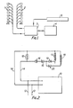
- the system as generally illustrated in Figure 1, requires a sensor 1 and a heat controller 2 for each space and a control centre incorporating a main control unit in the form of a processor and memory unit 3 and an operator and keyboard display unit 4, from which all spaces can be controlled and at which any information on space heating can be monitored and displayed.
- the sensors 1 and controllers 2 are linked with the main control unit through the wiring of an existing telephone. system.
- An outside temperature monitor 5 will also be linked to the processor unit 3.
- the display unit will display continuously the outside air temperature, the temperature of any space and heat consumption for any predetermined short period of any space as a ratio of the heating "on" time to the total time and average temperature. Heat consumption over the previous 12 hours for any space can also be displayed in a similar way.
- Inputs to the processor and memory unit 3 will include the requirements for the temperature of a space (there may be a zero heating requirement for any space unoccupied) and a warning level set for the heat consumption for any space. This will enable a check to be made for excessive consumption if a window was left open or an indication of small heat consumption might suggest a system or component malfunction. It is desirable to be able to modify the space temperature requirement for any particular space where the occupant requires a higher or lower room temperature. This can be done by dialling a special code on the telephone instrument (this code can be shown prominently on the telephone). Thus the occupant could dial three digits, the first two giving access to the system and the last one requesting more or less heat, for example in temperature increments of 2°C subject to a predetermined maximum.
- the advantages of the system include the features that heating is only provided when and where needed; the occupants have control over the temperature of the space they occupy up to a set maximum; and heat consumption is monitored so that abnormal high or low consumption will produce a warning signal (such as a flashing light) on the display unit 4. It would also be possible to monitor the total heat supplied by a main central heating boiler and compare this with the total heat consumption of all the heat control devices 2.
- the pulse controller valve is connected in the radiator feed pipe either to replace the normal valve or to be in series with it.
- Each sensor 1 and heat control device 2 can readily be incorporated in a fairly simple circuit as illustrated in Figure 2.
- Supply lines 12 to an individual telephone instrument 13 in a space to be heated are tapped by connections 14 incorporating the circuit.
- This circuit includes a thermistor 15 whose resistance will vary from a nominal 4.7 ohms at 25°C by 150 to 250 ohms per °C.
- An interrogation current pulse can be sent through the lines 14 to the thermistor 15 and a measurement of the voltage will give a direct indication of the temperature in the region surrounding the thermistor 15.
- Zener diodes 16 will provide a 15 volt threshold.
- the circuit also includes coils 17 and 18 each with a respective diode 19 or 20. These coils will control operation of a valve.
- the coil 17 will be energised whilst a pulse of opposite polarity will cause energisation of the coil 18.
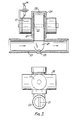
- the coils 17 and 18 are illustrated in the device shown in Figure 3.
- This valve incorporates a rotatable paddle 21 having a magnet 22 moulded therein.
- One end of the paddle is positioned within a pipe 23 of the central heating circuit whilst the other end is held by a cap 24 screwed onto the end of a T-piece 25.
- the pipe 23 and cap 24 provide bearings 26 for the paddle.
- Each pair of coils 17 or 18 incorporates a soft iron core 27 and whenone pair of coils is energised the paddle will be driven either into the open condition allowing liquid to flow along the pipe 23 or a closed position wherein the paddle blocks off this pipe. Once operated the valve will remain in position due to the permanent magnet 22 buried in the paddle 21.
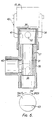
- valve illustrated in Figure 6 has a ported plug 31 instead of the paddle 21 of the device of Figure 3.
- This plug 31 (formed from polytetrafluorethylene) is set in a brass sleeve 37 in one arm of a T-piece 35 and has an L-shaped port 38 to allow flow from an inlet 39 to an outlet 40 of the T-piece.
- a rare earth or ceramic magnet 32 is fitted in the head 41 of the plug 31 and a brass end cap 34 seals the plug within the T-piece 35 and provides a bearing for a polytetrafluoroethylene pivot 36.
- the valve is operated by an electromagnet 42 provided with the oppositely wound coils 17, 18 for switching the plug 31 between the on and off positions.
- the electromagnet 42 is offset by 20° from the on and off positions of the plug 31 whose rotation is limited to an angle of 90° by a stop 43.
- the plug 31 could be set in the T-piece in the same attitude as for the paddle 21 of the valve of Figure 3, the plug 31 then having a straight-through port 38. Holes may be drilled through the plug body from the port 38 to communicate with the top and bottom surfaces of the head 41 of the plug 31 so as to allow for pressure equilisation on the plug 31 and reduce the torque required to move the valve.
- the manager or receptionist tells the control unit at what particular time the room is to be occupied and the temperature to which it should be heated.
- the system has previously learnt the thermal profile of that particular room and knows that for a given outside temperature, and a required inside temperature, a certain time will elapse before the room will reach the temperature required. It therefore calculates the time at which the heating input to the room should be increased. When this time is arrived at, the normal controlling sequence will be iniitiated for that particular room automatically.
- the control unit sequentially checks the temperature of each room and makes the decision to increase or reduce the heat input to the room. A pulse is then sent to the heat control valve concerned to open or close it.
- the information regarding the amount of heat that is being put into a particular room is stored in long-term memory and compared against a known profile of energy use for given outside temperature conditions. If the heat energy that is requested, and provided, is above the normal, then a warning is given to the manager or the receptionist, as it is likely that a window or door has been left open inadvertently. If the amount is lower than normal then the receptionist, (and possibly the maintenance section), is alerted to a probable malfunction of the valve, the heating system, or the control equipment.
- a fire detection programme sequence is initiated. This programme checks the temperature of each room and detects whether an abnormal change in temperature has occurred. The difference between this detection and normal fire detection (orsmoke detection) methods, is that the conventional type of alarm only detects a rise in temperature above pre-set limits, and very often false alarms are caused. The technique used here is much more exact. The system knows how much heat has been put into the room as well as the outside temperature and the temperature around the room. If the temperature has risen inside the room but this has not been caused by corresponding input of heat by the system, then a warning is given. As the level of the temperature before an alarm is requested can be determined by software instructions, full account can be taken of that particular room's thermal profile for all normal conditions.
- the warning can be given discretely because of the vast increase in the amount of time available to take emergency action.
- the system therefore, is not only self- checking but prevents needless disruption due to malfunction and false alarm. Because of the increased time given for action, the cause of the fire can be pinpointed with extreme accuracy obviating the need for early general alarm and subsequent possible panic. It is inevitable therefore that many lives that will otherwise be lost can be saved without the nuisance value of 'trigger happy' alarm systems.
- the system can be put back into its quiescent state either by the receptionist or by a system linked with the key check procedure in the case of hotels or by a 'system cancel' code on the telephone.
- the user of a room can interrupt the normal programme at any time by dialling a pre-set number on the telephone and either dialling a pre-set temperature or a rise in temperature, i.e. plus 2 degrees or 73 degrees F or 22 degrees C.
- a more expensive option is also the use of voice recognition in the system so that the user can actually communicate simply by speech.
- Predictive maintenance is also within the grasp of even the smallest hotels.
- the system will check over a period set by the user, how much heat is being used. This can be compared with the normal, and also with the fuel input to the heating system. A 'building efficiency' figure can thus be obtained for the complete building or parts of it.
- the intelligence of the unit will enable it to predict where and when a malfunction will occur next. This is particularly valuable with respect to the central heat generation in the boiler or heat pump, etc. but it also has value where, for instance, air- conditioning/cooling units that are independent to each room are used.
- the system does not necessarily have to use an existing telephone network but can use a simple two line 'highway' which is distributed around the buildings. This can be as unobstructive as the small twin wires associated with telephone installations. In this case, however, the rooms need a decoder fitted together with the temperature sensor in order that control instructions for that room only are to obeyed. The same decoder will be needed if the mains wiring is used for communication.
- control system can ----readily be used with a central heating based on ducted air or for controlling an air conditioning system.
- the system is intelligent and learns the response of the building, and each individual room, to variations in outside temperature.
- Abnormalities and fire detection can be identified down to the individual room in a matter of seconds.
- Temperature measurement and control can use existing telephone or mains systems wiring, keeping installation costs very low.
- the system is self-monitoring for malfunction.
- Heating plant maintenance requirements can be predicted in advance.
- the control unit can be interfaced with existing computing facilities to co-operate in conjunction with billing systems and room status systems for housekeeping departments.
- the room occupant has direct control over the temperature in that room, although the building manager has ultimate control over the maximum and minimum settings.
- the system can be extended to the heating plant control to improve the efficiency of boilers and heat exchangers, etc.
- Oral communication with the system will be possible for both the manager and the room occupant.
- the system can have a peak demand calculation ability into its intelligence so that load shedding can be applied (dependant upon the type of energy used) to take advantage of preferential ta riffs.
Claims (9)
Priority Applications (1)
| Application Number | Priority Date | Filing Date | Title |
|---|---|---|---|
| AT81305030T ATE25158T1 (de) | 1980-10-28 | 1981-10-26 | Waermeverbrauchersteuerungsanlagen. |
Applications Claiming Priority (2)
| Application Number | Priority Date | Filing Date | Title |
|---|---|---|---|
| GB8034672 | 1980-10-28 | ||
| GB8034672 | 1980-10-28 |
Publications (2)
| Publication Number | Publication Date |
|---|---|
| EP0050978A1 EP0050978A1 (de) | 1982-05-05 |
| EP0050978B1 true EP0050978B1 (de) | 1987-01-21 |
Family
ID=10516928
Family Applications (1)
| Application Number | Title | Priority Date | Filing Date |
|---|---|---|---|
| EP81305030A Expired EP0050978B1 (de) | 1980-10-28 | 1981-10-26 | Wärmeverbrauchersteuerungsanlagen |
Country Status (6)
| Country | Link |
|---|---|
| EP (1) | EP0050978B1 (de) |
| AT (1) | ATE25158T1 (de) |
| AU (1) | AU557709B2 (de) |
| DE (1) | DE3175863D1 (de) |
| ES (1) | ES8300208A1 (de) |
| GR (1) | GR75370B (de) |
Families Citing this family (5)
| Publication number | Priority date | Publication date | Assignee | Title |
|---|---|---|---|---|
| FR2536877A1 (fr) * | 1982-11-29 | 1984-06-01 | Encinas Victor | Procede et dispositif de programmation, de regulation, de controle d'economie du fonctionnement d'une installation de chauffage |
| US4616325A (en) * | 1983-06-17 | 1986-10-07 | Johnson Service Company | Zone condition controller and method of using same |
| FR2570821B1 (fr) * | 1984-09-25 | 1987-06-26 | Inovensea | Dispositif pour la surveillance des performances d'une installation de chauffage |
| EP0192228A3 (de) * | 1985-02-18 | 1987-06-16 | HAPPEL GmbH & Co. | Verfahren zum Regeln der Temperatur in Räumen durch Heiz- und/oder Kühleinrichtungen |
| FR2581218B1 (fr) * | 1985-04-30 | 1988-05-13 | Quille Sa | Procede de regulation d'un systeme de climatisation |
Family Cites Families (8)
| Publication number | Priority date | Publication date | Assignee | Title |
|---|---|---|---|---|
| US3400374A (en) * | 1965-06-16 | 1968-09-03 | Robertshaw Controls Co | Computerized control systems |
| US4021615A (en) * | 1975-07-30 | 1977-05-03 | Rca Corporation | Apparatus for conserving energy in a building |
| US4090248A (en) * | 1975-10-24 | 1978-05-16 | Powers Regulator Company | Supervisory and control system for environmental conditioning equipment |
| BE841601A (fr) * | 1976-05-07 | 1976-09-01 | Ensemble de reglage programme d'une installation de chauffage | |
| LU80763A1 (de) * | 1978-01-09 | 1979-05-16 | Lenz K | Verfahren und anordnung zur steuerung,ueberwachung und verbrauchsmessung eines fluiddurchflussventiles |
| DE2819032A1 (de) * | 1978-04-29 | 1979-11-08 | Walther Bueromasch Gmbh | Verfahren und vorrichtungsanordnung eines elektronisch gesteuerten heizkreisthermostaten |
| US4217646A (en) * | 1978-12-21 | 1980-08-12 | The Singer Company | Automatic control system for a building |
| PT69268A (en) * | 1979-01-23 | 1979-02-28 | Apparatus for producing bags of plastics material |
-
1981
- 1981-10-26 AT AT81305030T patent/ATE25158T1/de not_active IP Right Cessation
- 1981-10-26 DE DE8181305030T patent/DE3175863D1/de not_active Expired
- 1981-10-26 EP EP81305030A patent/EP0050978B1/de not_active Expired
- 1981-10-27 ES ES506594A patent/ES8300208A1/es not_active Expired
- 1981-10-28 AU AU76891/81A patent/AU557709B2/en not_active Withdrawn - After Issue
- 1981-10-29 GR GR66392A patent/GR75370B/el unknown
Also Published As
| Publication number | Publication date |
|---|---|
| GR75370B (de) | 1984-07-13 |
| EP0050978A1 (de) | 1982-05-05 |
| DE3175863D1 (en) | 1987-02-26 |
| ES506594A0 (es) | 1982-10-01 |
| AU7689181A (en) | 1982-05-06 |
| ES8300208A1 (es) | 1982-10-01 |
| ATE25158T1 (de) | 1987-02-15 |
| AU557709B2 (en) | 1987-01-08 |
Similar Documents
| Publication | Publication Date | Title |
|---|---|---|
| USRE48372E1 (en) | System and method for monitoring, controlling, and optimizing the use of utilities | |
| US4294404A (en) | Environmental control system | |
| US5801940A (en) | Fault-tolerant HVAC system | |
| US4174064A (en) | Energy control system providing selective control of remote zone heating or cooling from a central location | |
| US4587403A (en) | Thermostat setback controller sub-base | |
| CN101128855B (zh) | 紧急情况下提供遇难者位置信息的系统和方法 | |
| US5706191A (en) | Appliance interface apparatus and automated residence management system | |
| US5566879A (en) | System for centralized controlling of a plurality of temperature regulating devices | |
| US20020179723A1 (en) | Electronic mixed water preparation device and method for preparing mixed water | |
| EP2857921B1 (de) | Intelligentes Temperatursteuerungssystem | |
| RU2363973C2 (ru) | Модульная инженерная система | |
| CA2069273A1 (en) | Energy management systems | |
| US4671457A (en) | Method and apparatus for controlling room temperature | |
| US11313573B2 (en) | Load management system and method utilizing occupancy data and learned device behavior | |
| CA2115717A1 (en) | Method and apparatus for remote control of an electrical load | |
| US5538181A (en) | Automatic room occupancy controlled fuel savings system for air conditioning/heater units | |
| KR20140135155A (ko) | 건물의 난방 시스템에 대한 온도 제어 유닛에 대한 개선 | |
| EP0050978B1 (de) | Wärmeverbrauchersteuerungsanlagen | |
| EP0717332A1 (de) | Elektrisches Steuergerät für ein Stellorgan | |
| US4256258A (en) | Temperature monitor and alarm system | |
| US20080083403A1 (en) | System and method for monitoring heating system | |
| US4147302A (en) | Home heating system control | |
| JPH05157328A (ja) | ユニットベンチレータの制御装置 | |
| Harrold et al. | Automatic controls in building services | |
| JP6502562B1 (ja) | 発電システム |
Legal Events
| Date | Code | Title | Description |
|---|---|---|---|
| PUAI | Public reference made under article 153(3) epc to a published international application that has entered the european phase |
Free format text: ORIGINAL CODE: 0009012 |
|
| AK | Designated contracting states |
Designated state(s): AT BE CH DE FR GB IT LU NL SE |
|
| 17P | Request for examination filed |
Effective date: 19821028 |
|
| RAP1 | Party data changed (applicant data changed or rights of an application transferred) |
Owner name: MICROTEC SYSTEMS LIMITED |
|
| GRAA | (expected) grant |
Free format text: ORIGINAL CODE: 0009210 |
|
| AK | Designated contracting states |
Kind code of ref document: B1 Designated state(s): AT BE CH DE FR GB IT LI LU NL SE |
|
| PG25 | Lapsed in a contracting state [announced via postgrant information from national office to epo] |
Ref country code: NL Effective date: 19870121 Ref country code: IT Free format text: LAPSE BECAUSE OF FAILURE TO SUBMIT A TRANSLATION OF THE DESCRIPTION OR TO PAY THE FEE WITHIN THE PRESCRIBED TIME-LIMIT;WARNING: LAPSES OF ITALIAN PATENTS WITH EFFECTIVE DATE BEFORE 2007 MAY HAVE OCCURRED AT ANY TIME BEFORE 2007. THE CORRECT EFFECTIVE DATE MAY BE DIFFERENT FROM THE ONE RECORDED. Effective date: 19870121 Ref country code: FR Free format text: LAPSE BECAUSE OF NON-PAYMENT OF DUE FEES Effective date: 19870121 Ref country code: BE Effective date: 19870121 Ref country code: AT Effective date: 19870121 |
|
| REF | Corresponds to: |
Ref document number: 25158 Country of ref document: AT Date of ref document: 19870215 Kind code of ref document: T |
|
| PG25 | Lapsed in a contracting state [announced via postgrant information from national office to epo] |
Ref country code: SE Effective date: 19870131 |
|
| REF | Corresponds to: |
Ref document number: 3175863 Country of ref document: DE Date of ref document: 19870226 |
|
| REG | Reference to a national code |
Ref country code: CH Ref legal event code: PL |
|
| EN | Fr: translation not filed | ||
| NLV1 | Nl: lapsed or annulled due to failure to fulfill the requirements of art. 29p and 29m of the patents act | ||
| PG25 | Lapsed in a contracting state [announced via postgrant information from national office to epo] |
Ref country code: GB Effective date: 19871026 |
|
| PG25 | Lapsed in a contracting state [announced via postgrant information from national office to epo] |
Ref country code: LU Free format text: LAPSE BECAUSE OF NON-PAYMENT OF DUE FEES Effective date: 19871031 |
|
| PLBI | Opposition filed |
Free format text: ORIGINAL CODE: 0009260 |
|
| 26 | Opposition filed |
Opponent name: DANFOSS A/S Effective date: 19871020 |
|
| GBPC | Gb: european patent ceased through non-payment of renewal fee | ||
| RDAG | Patent revoked |
Free format text: ORIGINAL CODE: 0009271 |
|
| STAA | Information on the status of an ep patent application or granted ep patent |
Free format text: STATUS: PATENT REVOKED |
|
| GBPR | Gb: patent revoked under art. 102 of the ep convention designating the uk as contracting state | ||
| 27W | Patent revoked |
Effective date: 19880424 |
|
| REG | Reference to a national code |
Ref country code: CH Ref legal event code: PL |