EP0050955A2 - A vacuum interrupter - Google Patents
A vacuum interrupter Download PDFInfo
- Publication number
- EP0050955A2 EP0050955A2 EP81304914A EP81304914A EP0050955A2 EP 0050955 A2 EP0050955 A2 EP 0050955A2 EP 81304914 A EP81304914 A EP 81304914A EP 81304914 A EP81304914 A EP 81304914A EP 0050955 A2 EP0050955 A2 EP 0050955A2
- Authority
- EP
- European Patent Office
- Prior art keywords
- electrodes
- fixed
- pair
- vacuum interrupter
- movable
- Prior art date
- Legal status (The legal status is an assumption and is not a legal conclusion. Google has not performed a legal analysis and makes no representation as to the accuracy of the status listed.)
- Granted
Links
- 229910001152 Bi alloy Inorganic materials 0.000 claims description 2
- 230000001419 dependent effect Effects 0.000 claims 1
- 239000002184 metal Substances 0.000 abstract description 18
- 229910052751 metal Inorganic materials 0.000 abstract description 18
- 238000007789 sealing Methods 0.000 description 15
- 238000004519 manufacturing process Methods 0.000 description 10
- 230000002093 peripheral effect Effects 0.000 description 9
- 238000005219 brazing Methods 0.000 description 7
- 238000005242 forging Methods 0.000 description 6
- 239000000463 material Substances 0.000 description 5
- RYGMFSIKBFXOCR-UHFFFAOYSA-N Copper Chemical compound [Cu] RYGMFSIKBFXOCR-UHFFFAOYSA-N 0.000 description 4
- XEEYBQQBJWHFJM-UHFFFAOYSA-N Iron Chemical compound [Fe] XEEYBQQBJWHFJM-UHFFFAOYSA-N 0.000 description 4
- 229910052802 copper Inorganic materials 0.000 description 4
- 239000010949 copper Substances 0.000 description 4
- 239000012212 insulator Substances 0.000 description 3
- 229910001069 Ti alloy Inorganic materials 0.000 description 2
- 229910045601 alloy Inorganic materials 0.000 description 2
- 239000000956 alloy Substances 0.000 description 2
- 229910000963 austenitic stainless steel Inorganic materials 0.000 description 2
- 238000000151 deposition Methods 0.000 description 2
- 238000009826 distribution Methods 0.000 description 2
- 230000005684 electric field Effects 0.000 description 2
- 229910052742 iron Inorganic materials 0.000 description 2
- 229910000881 Cu alloy Inorganic materials 0.000 description 1
- 229910001030 Iron–nickel alloy Inorganic materials 0.000 description 1
- 229910017709 Ni Co Inorganic materials 0.000 description 1
- 229910003267 Ni-Co Inorganic materials 0.000 description 1
- 229910003262 Ni‐Co Inorganic materials 0.000 description 1
- PNEYBMLMFCGWSK-UHFFFAOYSA-N aluminium oxide Inorganic materials [O-2].[O-2].[O-2].[Al+3].[Al+3] PNEYBMLMFCGWSK-UHFFFAOYSA-N 0.000 description 1
- 238000005452 bending Methods 0.000 description 1
- 239000000919 ceramic Substances 0.000 description 1
- 230000007423 decrease Effects 0.000 description 1
- 230000008020 evaporation Effects 0.000 description 1
- 238000001704 evaporation Methods 0.000 description 1
- 230000004907 flux Effects 0.000 description 1
- 239000011521 glass Substances 0.000 description 1
- 238000010438 heat treatment Methods 0.000 description 1
- 239000011810 insulating material Substances 0.000 description 1
- 239000012774 insulation material Substances 0.000 description 1
- 238000005304 joining Methods 0.000 description 1
- 230000004807 localization Effects 0.000 description 1
- 239000000155 melt Substances 0.000 description 1
- 230000008018 melting Effects 0.000 description 1
- 238000002844 melting Methods 0.000 description 1
- 238000000034 method Methods 0.000 description 1
- 238000012986 modification Methods 0.000 description 1
- 230000004048 modification Effects 0.000 description 1
- 239000007779 soft material Substances 0.000 description 1
- 230000008646 thermal stress Effects 0.000 description 1
Images


Classifications
-
- H—ELECTRICITY
- H01—ELECTRIC ELEMENTS
- H01H—ELECTRIC SWITCHES; RELAYS; SELECTORS; EMERGENCY PROTECTIVE DEVICES
- H01H33/00—High-tension or heavy-current switches with arc-extinguishing or arc-preventing means
- H01H33/60—Switches wherein the means for extinguishing or preventing the arc do not include separate means for obtaining or increasing flow of arc-extinguishing fluid
- H01H33/66—Vacuum switches
- H01H33/662—Housings or protective screens
- H01H33/66207—Specific housing details, e.g. sealing, soldering or brazing
-
- H—ELECTRICITY
- H01—ELECTRIC ELEMENTS
- H01H—ELECTRIC SWITCHES; RELAYS; SELECTORS; EMERGENCY PROTECTIVE DEVICES
- H01H33/00—High-tension or heavy-current switches with arc-extinguishing or arc-preventing means
- H01H33/60—Switches wherein the means for extinguishing or preventing the arc do not include separate means for obtaining or increasing flow of arc-extinguishing fluid
- H01H33/66—Vacuum switches
- H01H33/664—Contacts; Arc-extinguishing means, e.g. arcing rings
- H01H33/6643—Contacts; Arc-extinguishing means, e.g. arcing rings having disc-shaped contacts subdivided in petal-like segments, e.g. by helical grooves
-
- H—ELECTRICITY
- H01—ELECTRIC ELEMENTS
- H01H—ELECTRIC SWITCHES; RELAYS; SELECTORS; EMERGENCY PROTECTIVE DEVICES
- H01H33/00—High-tension or heavy-current switches with arc-extinguishing or arc-preventing means
- H01H33/60—Switches wherein the means for extinguishing or preventing the arc do not include separate means for obtaining or increasing flow of arc-extinguishing fluid
- H01H33/66—Vacuum switches
- H01H33/662—Housings or protective screens
- H01H33/66207—Specific housing details, e.g. sealing, soldering or brazing
- H01H2033/66215—Details relating to the soldering or brazing of vacuum switch housings
-
- H—ELECTRICITY
- H01—ELECTRIC ELEMENTS
- H01H—ELECTRIC SWITCHES; RELAYS; SELECTORS; EMERGENCY PROTECTIVE DEVICES
- H01H33/00—High-tension or heavy-current switches with arc-extinguishing or arc-preventing means
- H01H33/60—Switches wherein the means for extinguishing or preventing the arc do not include separate means for obtaining or increasing flow of arc-extinguishing fluid
- H01H33/66—Vacuum switches
- H01H33/662—Housings or protective screens
- H01H33/66207—Specific housing details, e.g. sealing, soldering or brazing
- H01H2033/66223—Details relating to the sealing of vacuum switch housings
Definitions
- the present invention relates generally to a vacuum interrupter, and more specifically to a pair of electrodes of magnetic arc driving type used for the vacuum interrupter.
- a pair of electrodes In a vacuum interrupter, special structures have been devised for a pair of electrodes in order to improve the performance of current interruption.
- One of the examples of these structures is a pair of electrodes of magnetic arc driving type.
- each electrode of magnetic arc driving type is formed roughly in a disk shape having a circular recessed portion at the center of one surface thereof, a circular contact surface formed on the same surface thereof concentric with the circular recessed portion, and a number of separate arc-driving members extending from the peripheral edges thereof to the center thereof in a straight line or a spiral form around the contact surface thereof.
- the arc-driving members are radially symmetrical with respect to the center of the electrode in order to effectively drive the arc, generated whenever the electrodes are closed or opened, outwardly, and two types of electrodes having two different shapes opposite to each other with respect to the cross section are used for the movable electrode and fixed electrode, independently.
- the invention as claimed provides:
- a vacuum interrupter comprises a pair of electrodes both the electrode surfaces of which are formed symmetrically with respect to the central axis in the cross section thereof with the same cross section and the same shape and which are provided with a number of arc driving members to drive the arc generated between the electrodes.
- the arc generated between the electrodes becomes less uniformly distributed across the electrode surfaces, and is usually concentrated partially on some portion thereon.
- the metal is subject to evaporation, and thus ensuring that the arc generated therebetween stays at this portion. Therefore, the surface of the electrode melts markedly, thus resulting in localization of subsequent arcs, lowering the electrical withstanding voltage, and then reignition or restriking occurs between a pair of electrodes.
- the magnetic arc driving method is one attempt to prevent partial melting of the electrodes by applying a magnetic field in the lateral direction of the arc to drive the arc outwardly from the arc generation position depending upon a force measured by multiplication .of current by magnetic flux density (I x B).
- the typical electrode is a spiral electrode as depicted in Figs. 1(A) and (B), in which a pair of prior-art spiral electrodes of magnetic arc driving type are shown in a cross-sectional view and a top view.
- the arc (b-c) generated first at the contact portion of the electrodes is driven outwardly by the influence of magnetic field produced by the current through the parts (a-b) and (c-d).
- the current flowing through the electrode (g-h) flows in the spiral route on the arc driving member of the electrode as depicted by a dotted line of Fig. l(B). Accordingly, this current can be divided into two components of m (circumferential direction) and 1 (radial direction).
- the current component m in this circumferential direction generates a magnetic field in H-direction of Fig.
- a pair of fixed-side end plates 201 and movable-side end plate 202 made of inorganic insulating material are hermetically joined to both the ends of a cylindrical metal housing 1 with a pair of auxiliary sealing members 301 and 302 with a L-shaped cross section hermetically disposed therebetween in order to form a vacuum vessel 4 usable under a high vacuum.
- a pair of electrode rods, one fixed 5 and one movable 6, are inserted through the central portions of the fixed-side end plate 201 and the movable-side end plate 202 respectively along the axial direction of the vacuum vessel 4 (vertical direction in Fig. 2).
- a pair of electrodes comprising a /fixed electrode 7 and movable electrode 8 of magnetic arc driving type are fixed, respectively.
- the cylindrical metal housing 1, constituting a part of the vacuum vessel 4, is made of, for instance, austenitic stainless steel, copper, or iron.
- Metallized portions 901 and 902 are formed on the inner peripheral portions of the fixed-side end plate 201 and the movable-side end plate 202 respectively.
- auxiliary sealing member 301 and 302 with an L-shaped cross-section, each of which includes a cylindrical portion 301a or 302a extending in the axial direction thereof (vertical direction in Fig. 2) and a flange portion 301b or 3.02b extending in the radial direction thereof (horizontal direction in Fig.
- each cylindrical portion 301a or 302a is in contact with each metallized portion 901 or 902 of each end plate 201 or 202 and each flange portion 301b or 302b is in contact with each flange portion 101a or 102a of the fixed-side and movable-side auxiliary shield 101 or 102.
- Each auxiliary sealing member 301 or 302 is used for improving the reliability of the hermetic seal between the cylindrical metal housing 1 and the fixed-side end plate 201 and the movable-side end plate 202, because the thermal expansion coefficients of these two materials differ.
- the auxiliary sealing members 301 and 302 are made of a relatively soft material such as copper, and therefore are deformable to reduce the thermal stress between the cylindrical metal cylinder housing and the fixed-side and movable-side end plates generated when these two members are brazed to each other and cooled after brazing.
- copper it is also possible to use iron, a Fe-Ni-Co alloy, or a Fe-Ni alloy for the material of the first auxiliary sealing members 301 and 302.
- the fixed-side and movable-side end plates are made of inorganic insulation material each such as alumina ceramics or crystallized glass, and is formed into a disk shape having a hole 111 or 112 at the center thereof.
- metallized layers 121 and 122 are formed Near each inner surface of each hole 111 or 112, metallized layers 121 and 122 are formed.
- this metallized layer is formed of a Mn-Ti alloy or a Mo-Mn-Ti alloy, thermal expansion coefficient of which is roughly the same as that of the fixed-side and movable-side end plate for protection of bonding strength therebetween.
- a plurality of annular projection portions 141 or 142 with a 0.1-0.5 mm height respectively are formed on each circumferential portion 131 or 132 of each fixed-side or movable-side end plate 201 or 202.
- the fixed-side and movable-side end plates 201 and 202 are hermetically joined to either end of the cylindrical metal housing 1 through the first auxiliary sealing members 301 and 302
- a ring-shaped auxiliary sealing member 15 with a L -shaped cross section which includes a cylindrical portion 15a extending in the axial direction thereof (vertical direction in Fig. 2) and a flange portion 15b extending in the radial direction thereof (horizontal direction in Fig. 2) is fitted and hermetically joined to the hole 111 of the fixed-side end plate 201 in such a way that the flange portion 15b is in contact with the central portion of the outside surface of the fixed-side end plate 201 and the cylindrical portion 15a is almost in contact with the hole 111 of the fixed-side end plate 201.
- the fixed electrode rod 5 made of copper or a copper alloy is inserted through the disc-shaped auxiliary sealing member 15 fitted to the hole 111 formed in the fixed-side end plate 201.
- the movement of the fixed electrode rod 5 in the axial direction thereof is restricted when a first retainer 16 fitted to a peripheral groove 5a provided around an outer portion of the fixed electrode rod 5 is brought into contact with the outer surface of the disc-shaped auxiliary sealing member 15, and the fixed electrode rod 5 is then hermetically joined by brazing to the cylindrical portion 15a of the disc-shaped auxiliary sealing member 15.
- the ring-shaped auxiliary sealing member 15 is used for joining the insulator end plate 2 with the fixed electrode rod 5 with a secure seal in spite of the fact that there is a difference in thermal expansion coefficient between the fixed-side end plate 201 and the fixed electrode rod 5, being made of the same metal as that of the disc-shaped auxiliary sealing member 301.
- a threaded portion 5b is provided at the top end portion of the fixed electrode rod 5
- a flange portion 5c integrally formed therewith is provided at the bottom end portion of the fixed electrode rod 5 so as to form a current contact area when brought into contact with a fixed electrode 7 described hereinafter.
- a second retainer 17 is fitted to the second retainer 17, a fixed-side main are-shield 191 formed in a cup-shape having a diameter larger than that of the auxiliary shield 101 is fitted and fixed by brazing so as to restrict the movement thereof in the axial direction thereof.
- the cylindrical portion 191a of the fixed-side main arc-shield 191 opens upward facing the auxiliary shield 101 and serves to make uniform the distribution of the electric field within the vacuum vessel 4 in coopration with the auxiliary shield 101 provided on the fixed-side and additionally to prevent metal vapour from depositing onto the inner surface of the fixed-side end plate 201, for this purpose, the fixed-side auxiliary shield 101 and fixed-side main arc shield 191 overlap each other concentrically.
- an austenitic stainless steel bellows 20 housed concentrically within the vacuum vessel 4 is attached by way of a cylindrical portion 20a formed by extending the inner diameter of the outer end thereof in the axial direction and hermetically joined by brazing to the metallized layer 122.
- a mounting portion 20b with a V-shaped cross section formed by extending the inner diameter of the inner end thereof in the axial direction and by bending it toward the axis of the vacuum vessel 4.
- the movable electrode rod 6 formed into almost the same shape as that of the fixed electrode rod 5 is inserted through the central hole 112 and the bellows 20.
- the above-mentioned movable electrode rod 6 is made of the same metal as that of the fixed electrode rod 5 and has a peripheral groove 6a on an outer portion thereof, a threaded portion 6b at the outer end thereof in order to connect an vacuum interrupter operating device (not shown), a flange portion 6c at the inner end thereof as a current contact area integrally formed therewith, and another peripheral groove 6d near the flange portion 6c.
- the movement of the movable electrode rod 6 in the axial direction thereof is restricted by a third retainer 21 fitted to the peripheral groove 6d provided near the inner end portion of the movable electrode rod 6 in conjunction with the mounting portion 20b of the bellows 20, and the movable electrode rod 6 is hermetically joined by brazing to the mounting portion 20b of the bellows 20.
- the movable-side main arc-shield 192 is attached between the flange portion 6c of the movable electrode rod 6 and the peripheral groove 6d provided near the flange portion 6c and is formed into a cup shape having a larger diameter than that of the fixed-side auxiliary shield 101 on the fixed-side end plate side.
- the main arc-shield 192 opens downward facing the movable-side auxiliary shield 102 and also serves to make uniform the distribution of the electric field within the vacuum vessel 4 in cooperation with the the movable-side auxiliary shield 102 provided on the lower side and additionally to prevent metal vapour from depositing onto the bellows 20 and the inner surface of the movable-side end plate 202.
- the main arc-shields 192 and auxiliary shield 102 overlap each other concentrically.
- each electrode 7 or 8 is of a roughly disc shape provided with a through hole 24 at the center thereof in the axial direction (vertical direction in Fig. 4).
- the diameter of the hole 24 is almost the same as that of each electrode rod 5 or 6.
- two recessed fitting portions 25a and 25b are provided having almost the same diameter as that of the flange portion 5c or 6c of each electrode rod 5 or 6 respectively.
- the recessed fitting portions 25a and 25b serve to fix the electrodes 7 and 8 onto the electrode rods 5 and 6 respectively.
- each electrode 7 and 8 a plurality of arc driving member 7a formed by slits are provided in order to drive the arc, generated when the electrodes are closed or opened, outwardly, starting from a plurality of positions on the outer peripheral portion thereof and leading to near the recessed fitting portions 25a and 25b with approximately the same spacing throughout.
- the fixed electrode 7 is fitted to the fixed electrode rod 5 through the hole 24, and either of the recessed fitting portion 25a or 25b is fitted and fixed to the flange portion 5c of the fixed electrode rod 5.
- the movable electrode 8 is fitted and fixed to the flange portion 6c of the movable electrode rod 6 with either of the recessed fitting portion 25a or 25b being brought into contact with the flange portion 6c of the movable electrode rod 6.
- a ring-shaped contact member 27 (Fig. 1) formed with an L-shaped cross section, which includes a cylinder portion extending in the axial direction thereof and having almost the same diameter as that of the hole 24 of the movable electrode 8 and a flange portion extending in the radial direction and having almost the same diameter as that of the recessed fitting portion 25b or 25a, is fitted and fixed by brazing, as shown in Fig. 2, in such a way that its cylindrical portion and some part of its flange portion respectively are fitted to the hole 24 and the recessed fitting portion 25b or 25a of the movable electrode 8.
- the contact member 27 is made of a material having a high antiweld property such as a Cu-Bi alloy in order to improve the welds of the fixed and movable electrodes 7 and 8; however, being not limited to this material, it is of course possible to form at least one of the flange portions 5c and 6c of the fixed electrode 5 and movable electrode 6, respectively, of a material having a high antiweld property.
- the flange 5c and the contact member 27 serve to drive the arc by the arc driving members 7a of the electrodes 7 and 8, as described with reference to Fig. 1.
- slits 26 provided in the fixed and movable electrodes 7 and 8 are illustrated in the form of a spiral, it is possible to use slits of other forms, such as shown in Figs. 5 and 6, which start from a plurality of positions along the circumference and lead to near the recessed fitting portions 25a and 25b in a straight line, maintaining approximately the same spacing.
- slits 26 in the electrodes at an appropriate predetermined angle with respect to the axis thereof (vertical direction in Fig. 4).
- the arc-driving members 7a and 8a of the fixed electrode 7 and the movable electrode 8 can be formed in a disc shape having a tapered periphery 28 in vertical cross-section in which the wall thickness decreases as it reaches the outer diameter side, as shown in Fig. 7.
- a pair of the magnetic arc driving type electrodes are formed symmetrically with respect to the cross section perpendicular to the axial direction thereof, that is, along the arc-running direction, it is possible to use only one kind of magnetic arc driving electrode in the vacuum interrupter. Therefore, the electrodes can be manufactured in mass production steps by using only a single forging metal die, thus reducing the number of manufacturing steps and the manufacturing cost markedly.
Abstract
Description
- The present invention relates generally to a vacuum interrupter, and more specifically to a pair of electrodes of magnetic arc driving type used for the vacuum interrupter.
- In a vacuum interrupter, special structures have been devised for a pair of electrodes in order to improve the performance of current interruption. One of the examples of these structures is a pair of electrodes of magnetic arc driving type.
- In a vacuum interrupter provided with a pair of electrodes of magnetic arc driving type within the vacuum vessel, each electrode of magnetic arc driving type is formed roughly in a disk shape having a circular recessed portion at the center of one surface thereof, a circular contact surface formed on the same surface thereof concentric with the circular recessed portion, and a number of separate arc-driving members extending from the peripheral edges thereof to the center thereof in a straight line or a spiral form around the contact surface thereof.
- In a pair of conventional electrodes of magnetic arc driving type used with the vacuum interrupter, the arc-driving members are radially symmetrical with respect to the center of the electrode in order to effectively drive the arc, generated whenever the electrodes are closed or opened, outwardly, and two types of electrodes having two different shapes opposite to each other with respect to the cross section are used for the movable electrode and fixed electrode, independently.
- Accordingly, in order to manufacture these electrodes of magnetic arc driving type by using, for example, forging steps, two kinds of d.ifferent metal forging dies must be prepared for the reason explained above, thus increasing the number of manufacturing steps and the manufacturing cost. prior art
- A more detailed description of / electrodes of magnetic arc driving type will be made with reference to Figures 1(A) and 1(B) of the attached drawings.
- With these problems in mind therefore, it is a primary object of the present invention to provide a vacuum interrupter provided with a pair of electrodes of magnetic arc driving type, in which a single form can be used for the fixed and movable electrodes in common, so that it is possible to reduce the number of metal forging dies, manufacturing steps, and manufacturing cost.
- The invention as claimed provides:
- A vacuum interrupter having a pair of roughly disc-shaped electrodes of magnetic arc driving type disposed within a vacuum vessel so as to be brought into contact with or separated from each other for current interruption, CHARACTERIZED IN THAT:
- a pair of said electrodes of magnetic arc driving type are formed in such a way that both the electrode surfaces of a pair of said electrodes are formed symmetrically with respect to the central axis of the cross section thereof perpendicular to the axial direction of said electrodes.
- To achieve the above-mentioned object, a vacuum interrupter according to the present invention comprises a pair of electrodes both the electrode surfaces of which are formed symmetrically with respect to the central axis in the cross section thereof with the same cross section and the same shape and which are provided with a number of arc driving members to drive the arc generated between the electrodes.
- Ways of carrying out the invention are described in. detail below with reference to drawings which illustrate three specific embodiments.
- In the accompanying drawings like reference numerals designate corresponding elements and in the drawings:
- Fig. 1(A) is a cross sectional view of a pair of prior-art electrodes of magnetic arc driving type-Fig. 1(B) is a top view of the pair of prior-art electrodes of magnetic arc driving type in the direction shown by the arrows B-B in Fig. 1;
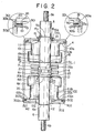
- Fig. 2 is a longitudinal cross-sectional view of a preferred embodiment of the vacuum interrupter according to the present invention;
- Fig. 3 is a top view of a first preferred embodiment of an electrode of magnetic arc driving type used with the vacuum interrupter according to the present invention;
- Fig. 4 is a cross-sectional view taken along the lines IV-IV of Fig. 3;
- Fig. 5 is a top view of a second preferred embodiment of the electrode of magnetic arc driving type used with the vacuum interrupter according to the present invention;
- Fig. 6 is a cross-sectional view taken along the lines VI-VI of Fig. 5; and
- Fig. 7 is a cross-sectional view of a third preferred embodiment of the electrode of magnetic arc driving type used with the vacuum interrupter according to the present invention.
- To facilitate understanding of the present embodiments, a brief reference will be made hereinafter to a pair of prior-art electrodes of magnetic arc driving type used for a vacuum interrupter, with reference to Fig. 1(A) and (B).
- In vacuum interrupters of magnetic arc driving type, as the rated breaking current increase, and therefore the diameter of the electrodes increase, the arc generated between the electrodes becomes less uniformly distributed across the electrode surfaces, and is usually concentrated partially on some portion thereon. At the corner portion of the electrode, in particular, the metal is subject to evaporation, and thus ensuring that the arc generated therebetween stays at this portion. Therefore, the surface of the electrode melts markedly, thus resulting in localization of subsequent arcs, lowering the electrical withstanding voltage, and then reignition or restriking occurs between a pair of electrodes.
- The magnetic arc driving method is one attempt to prevent partial melting of the electrodes by applying a magnetic field in the lateral direction of the arc to drive the arc outwardly from the arc generation position depending upon a force measured by multiplication .of current by magnetic flux density (I x B). The typical electrode is a spiral electrode as depicted in Figs. 1(A) and (B), in which a pair of prior-art spiral electrodes of magnetic arc driving type are shown in a cross-sectional view and a top view.
- In these figures, the arc (b-c) generated first at the contact portion of the electrodes is driven outwardly by the influence of magnetic field produced by the current through the parts (a-b) and (c-d). Next, when taking into account the case where the arc (b-c) moves to the position (f-g), since a number of spiral slits are provided in the electrode surface, the current flowing through the electrode (g-h) flows in the spiral route on the arc driving member of the electrode as depicted by a dotted line of Fig. l(B). Accordingly, this current can be divided into two components of m (circumferential direction) and 1 (radial direction). The current component m in this circumferential direction generates a magnetic field in H-direction of Fig. 1(A), and the arc is driven in the circumferential direction, that is, in F-direction of Fig. l(B) by the mutual operation of this magnetic field H and the arc (g-f). Since the arc is driven in the circumferential direction along the electrode surface, partial heating can be minimized on the electrode surface, thus increasing the upper limit of current interruption. It is possible to explain the movement due to the current (e-f) in the radial direction analogously to the current (g-h).
- In a pair of conventional electrodes of magnetic arc driving type used with the vacuum interrupter, however, although the arc driving members are formed symmetrically with respect to the center of the electrode to effectively drive the arc (generated whenever the electrodes are closed or opened) outwardly, two types of electrodes of the fixed respectively and movable electrodes¡, the electrode surfaces of which are independently formed symmetricaly with respect to the central axis thereof, are used with the single vacuum interrupter. Accordingly, in order to manufacture these electrodes of magnetic arc driving type by using, for example, forging steps, two kinds of different metal forging dies must be prepared, thus increasing the member of manufacturing steps and the manufaturing cost.
- In view of the above description, reference is now made to Figs. 2 to 7, and more specifically to Fig. 2, in which a preferred embodiment of a vacuum interrupter according to the present invention is illustrated by way of example with a pair of electrodes of magnetic arc driving type improved as described in more detail hereinafter.
- With reference to Fig. 2, there is explained hereinbelow the structure of the vacuum interrupter embodying the present invention.
- In this interrupter, a pair of fixed-
side end plates 201 and movable-side end plate 202 made of inorganic insulating material are hermetically joined to both the ends of acylindrical metal housing 1 with a pair ofauxiliary sealing members vacuum vessel 4 usable under a high vacuum. - Within this
vacuum vessel 4, a pair of electrode rods, one fixed 5 and one movable 6, are inserted through the central portions of the fixed-side end plate 201 and the movable-side end plate 202 respectively along the axial direction of the vacuum vessel 4 (vertical direction in Fig. 2). - To the respective inside ends of the fixed one and the other of
electrode rod 5 andmovable electrode rod 6,/ a pair of electrodes comprising a /fixed electrode 7 andmovable electrode 8 of magnetic arc driving type are fixed, respectively. - The
cylindrical metal housing 1, constituting a part of thevacuum vessel 4, is made of, for instance, austenitic stainless steel, copper, or iron. Metallizedportions side end plate 201 and the movable-side end plate 202 respectively. - In addition, a pair of disc-shaped
auxiliary sealing member cylindrical portion 301a or 302a extending in the axial direction thereof (vertical direction in Fig. 2) and aflange portion 301b or 3.02b extending in the radial direction thereof (horizontal direction in Fig. 2) perpendicular to thecylindrical portion 301a or 302a, respectively, are fitted and hermetically joined by brazing in such a way that eachcylindrical portion 301a or 302a is in contact with eachmetallized portion end plate flange portion flange portion 101a or 102a of the fixed-side and movable-sideauxiliary shield 101 or 102. - Each
auxiliary sealing member cylindrical metal housing 1 and the fixed-side end plate 201 and the movable-side end plate 202, because the thermal expansion coefficients of these two materials differ. Theauxiliary sealing members auxiliary sealing members - In this embodiment, the fixed-side and movable-side end plates are made of inorganic insulation material each such as alumina ceramics or crystallized glass, and is formed into a disk shape having a
hole - Near each inner surface of each
hole metallized layers metallized layers - In addition, a plurality of
annular projection portions circumferential portion 131 or 132 of each fixed-side or movable-side end plate side end plates cylindrical metal housing 1 through the firstauxiliary sealing members vacuum vessel 4 by hermetically sealing an insulator cylinder housing with a pair of metal end plates by using a pair of sealing metal members fixed on either end of the insulator cylinder housing. - A ring-shaped
auxiliary sealing member 15 with a L-shaped cross section, which includes acylindrical portion 15a extending in the axial direction thereof (vertical direction in Fig. 2) and a flange portion 15b extending in the radial direction thereof (horizontal direction in Fig. 2) is fitted and hermetically joined to thehole 111 of the fixed-side end plate 201 in such a way that the flange portion 15b is in contact with the central portion of the outside surface of the fixed-side end plate 201 and thecylindrical portion 15a is almost in contact with thehole 111 of the fixed-side end plate 201. - Within the
vacuum vessel 4, thefixed electrode rod 5 made of copper or a copper alloy is inserted through the disc-shapedauxiliary sealing member 15 fitted to thehole 111 formed in the fixed-side end plate 201. During assembly, the movement of thefixed electrode rod 5 in the axial direction thereof is restricted when a first retainer 16 fitted to aperipheral groove 5a provided around an outer portion of thefixed electrode rod 5 is brought into contact with the outer surface of the disc-shapedauxiliary sealing member 15, and thefixed electrode rod 5 is then hermetically joined by brazing to thecylindrical portion 15a of the disc-shapedauxiliary sealing member 15. - In the same way as with the disc-shaped
auxiliary sealing member 301 disposed between thecylindrical metal housing 1 and the fixed-side end plate 201, the ring-shapedauxiliary sealing member 15 is used for joining the insulator end plate 2 with thefixed electrode rod 5 with a secure seal in spite of the fact that there is a difference in thermal expansion coefficient between the fixed-side end plate 201 and thefixed electrode rod 5, being made of the same metal as that of the disc-shapedauxiliary sealing member 301. - Alao, a threaded
portion 5b is provided at the top end portion of the fixedelectrode rod 5, and aflange portion 5c integrally formed therewith is provided at the bottom end portion of the fixedelectrode rod 5 so as to form a current contact area when brought into contact with afixed electrode 7 described hereinafter. - Near the
flange portion 5c, another peripheral groove 5d is formed, into which asecond retainer 17 is fitted. To thesecond retainer 17, a fixed-side main are-shield 191 formed in a cup-shape having a diameter larger than that of theauxiliary shield 101 is fitted and fixed by brazing so as to restrict the movement thereof in the axial direction thereof. - The
cylindrical portion 191a of the fixed-side main arc-shield 191 opens upward facing theauxiliary shield 101 and serves to make uniform the distribution of the electric field within thevacuum vessel 4 in coopration with theauxiliary shield 101 provided on the fixed-side and additionally to prevent metal vapour from depositing onto the inner surface of the fixed-side end plate 201, for this purpose, the fixed-sideauxiliary shield 101 and fixed-sidemain arc shield 191 overlap each other concentrically. - On the other hand, to a
hole 112 formed in the movable-side end plate 202, an austeniticstainless steel bellows 20 housed concentrically within thevacuum vessel 4 is attached by way of a cylindrical portion 20a formed by extending the inner diameter of the outer end thereof in the axial direction and hermetically joined by brazing to themetallized layer 122. - Also, at the inner end portion of the
bellows 20, there is provided amounting portion 20b with a V-shaped cross section formed by extending the inner diameter of the inner end thereof in the axial direction and by bending it toward the axis of thevacuum vessel 4. - And, within the
vacuum vessel 4, themovable electrode rod 6 formed into almost the same shape as that of thefixed electrode rod 5 is inserted through thecentral hole 112 and thebellows 20. The above-mentionedmovable electrode rod 6 is made of the same metal as that of thefixed electrode rod 5 and has aperipheral groove 6a on an outer portion thereof, a threadedportion 6b at the outer end thereof in order to connect an vacuum interrupter operating device (not shown), aflange portion 6c at the inner end thereof as a current contact area integrally formed therewith, and anotherperipheral groove 6d near theflange portion 6c. During assembly, the movement of themovable electrode rod 6 in the axial direction thereof is restricted by athird retainer 21 fitted to theperipheral groove 6d provided near the inner end portion of themovable electrode rod 6 in conjunction with the mountingportion 20b of thebellows 20, and themovable electrode rod 6 is hermetically joined by brazing to the mountingportion 20b of thebellows 20. - The movable-side main arc-
shield 192 is attached between theflange portion 6c of themovable electrode rod 6 and theperipheral groove 6d provided near theflange portion 6c and is formed into a cup shape having a larger diameter than that of the fixed-sideauxiliary shield 101 on the fixed-side end plate side. - The main arc-
shield 192 opens downward facing the movable-side auxiliary shield 102 and also serves to make uniform the distribution of the electric field within thevacuum vessel 4 in cooperation with the the movable-side auxiliary shield 102 provided on the lower side and additionally to prevent metal vapour from depositing onto thebellows 20 and the inner surface of the movable-side end plate 202. For this purpose, the main arc-shields 192 and auxiliary shield 102 overlap each other concentrically. - As shown in Fig. 2, at the inner end portions of the above-mentioned, fixed
electrode rod 5. andmovable electrode rod 6, one hand the otherof a pair of a electrodes comprising a fixedelectrode 7 andmovable electrode 8 of magnetic arc driving type are fixed. In the fixed andmovable electrodes electrode hole 24 at the center thereof in the axial direction (vertical direction in Fig. 4). The diameter of thehole 24 is almost the same as that of eachelectrode rod hole 24 in both the electrode surfaces, two recessedfitting portions flange portion electrode rod - The recessed
fitting portions electrodes electrode rods - Further, in each
electrode arc driving member 7a formed by slits are provided in order to drive the arc, generated when the electrodes are closed or opened, outwardly, starting from a plurality of positions on the outer peripheral portion thereof and leading to near the recessedfitting portions - The fixed
electrode 7 is fitted to the fixedelectrode rod 5 through thehole 24, and either of the recessedfitting portion flange portion 5c of the fixedelectrode rod 5. - On the other hand, the
movable electrode 8 is fitted and fixed to theflange portion 6c of themovable electrode rod 6 with either of the recessedfitting portion flange portion 6c of themovable electrode rod 6. - To the other recessed
fitting portion movable electrode 8, a ring-shaped contact member 27 (Fig. 1) formed with an L-shaped cross section, which includes a cylinder portion extending in the axial direction thereof and having almost the same diameter as that of thehole 24 of themovable electrode 8 and a flange portion extending in the radial direction and having almost the same diameter as that of the recessedfitting portion hole 24 and the recessedfitting portion movable electrode 8. - Furthermore, the
contact member 27 is made of a material having a high antiweld property such as a Cu-Bi alloy in order to improve the welds of the fixed andmovable electrodes flange portions electrode 5 andmovable electrode 6, respectively, of a material having a high antiweld property. - In this embodiment, the
flange 5c and thecontact member 27 serve to drive the arc by thearc driving members 7a of theelectrodes - In the above-mentioned embodiment of a vacuum interrupter, although the
slits 26 provided in the fixed andmovable electrodes fitting portions - In addition, it is possible to provide
slits 26 in the electrodes at an appropriate predetermined angle with respect to the axis thereof (vertical direction in Fig. 4). - Further, the arc-driving
members electrode 7 and themovable electrode 8 can be formed in a disc shape having a taperedperiphery 28 in vertical cross-section in which the wall thickness decreases as it reaches the outer diameter side, as shown in Fig. 7. - As described above, in a vacuum interrupter having a pair of disc-shaped electrodes of magnetic arc driving type disposed within the vacuum vessel so as to be brought into contact with or separated from each other for current interruption, since a pair of the magnetic arc driving type electrodes are formed symmetrically with respect to the cross section perpendicular to the axial direction thereof, that is, along the arc-running direction, it is possible to use only one kind of magnetic arc driving electrode in the vacuum interrupter. Therefore, the electrodes can be manufactured in mass production steps by using only a single forging metal die, thus reducing the number of manufacturing steps and the manufacturing cost markedly.
- It will be understood by those skilled in the art that the foregoing description is in terms of preferred embodiments of the present invention wherein various changes and modifications may be made without departing from the spirit and scope of the invention, as set forth in the appended claims.
Claims (6)
Applications Claiming Priority (2)
| Application Number | Priority Date | Filing Date | Title |
|---|---|---|---|
| JP1980150277U JPS5772527U (en) | 1980-10-21 | 1980-10-21 | |
| JP150277/80U | 1980-10-21 |
Publications (3)
| Publication Number | Publication Date |
|---|---|
| EP0050955A2 true EP0050955A2 (en) | 1982-05-05 |
| EP0050955A3 EP0050955A3 (en) | 1983-02-09 |
| EP0050955B1 EP0050955B1 (en) | 1986-01-22 |
Family
ID=15493442
Family Applications (1)
| Application Number | Title | Priority Date | Filing Date |
|---|---|---|---|
| EP81304914A Expired EP0050955B1 (en) | 1980-10-21 | 1981-10-20 | A vacuum interrupter |
Country Status (4)
| Country | Link |
|---|---|
| US (1) | US4446346A (en) |
| EP (1) | EP0050955B1 (en) |
| JP (1) | JPS5772527U (en) |
| DE (1) | DE3173578D1 (en) |
Cited By (1)
| Publication number | Priority date | Publication date | Assignee | Title |
|---|---|---|---|---|
| DE3628174A1 (en) * | 1986-08-20 | 1988-02-25 | Calor Emag Elektrizitaets Ag | Vacuum switching chamber |
Families Citing this family (8)
| Publication number | Priority date | Publication date | Assignee | Title |
|---|---|---|---|---|
| US4672156A (en) * | 1986-04-04 | 1987-06-09 | Westinghouse Electric Corp. | Vacuum interrupter with bellows shield |
| US4936030A (en) * | 1987-06-23 | 1990-06-26 | Rennex Brian G | Energy efficient running shoe |
| EP0563830B1 (en) * | 1992-03-31 | 1995-01-11 | Siemens Aktiengesellschaft | Vacuum tube for low and middle tension switch, particularly for vacuum contactor |
| EP1367619B1 (en) * | 1995-09-04 | 2005-03-09 | Kabushiki Kaisha Toshiba | Vacuum valve |
| CN100555496C (en) * | 2007-08-07 | 2009-10-28 | 苑舜 | High capacity vacuum load switch |
| CN101834088B (en) * | 2010-05-12 | 2012-07-04 | 山东泰开真空开关有限公司 | Vacuum arc-extinguishing device for ultrahigh-voltage isolation |
| US9177742B2 (en) * | 2011-10-18 | 2015-11-03 | G & W Electric Company | Modular solid dielectric switchgear |
| CN103971985A (en) * | 2013-02-01 | 2014-08-06 | 西门子公司 | Contact elements and contact system for vacuum switch tube |
Citations (3)
| Publication number | Priority date | Publication date | Assignee | Title |
|---|---|---|---|---|
| DE1911071B2 (en) * | 1968-03-08 | 1977-12-29 | General Electric Co., Schenectady, N.Y. (V.St.A.) | VACUUM SWITCH |
| DD134897A1 (en) * | 1978-03-06 | 1979-03-28 | Gerhard Moennig | SWITCH ELECTRODE PAIR FOR VACUUM SWITCH |
| EP0017378A1 (en) * | 1979-03-23 | 1980-10-15 | Kabushiki Kaisha Meidensha | Vacuum circuit interrupter |
Family Cites Families (6)
| Publication number | Priority date | Publication date | Assignee | Title |
|---|---|---|---|---|
| DE134897C (en) * | ||||
| US3182156A (en) * | 1961-09-19 | 1965-05-04 | Gen Electric | Vacuum-type circuit interrupter |
| US3462572A (en) * | 1966-10-03 | 1969-08-19 | Gen Electric | Vacuum type circuit interrupter having contacts provided with improved arcpropelling means |
| US3522399A (en) * | 1968-03-08 | 1970-07-28 | Gen Electric | Vacuum-type circuit interrupter with contacts having particularly shaped circumferentially spaced slots |
| US3727018A (en) * | 1971-09-16 | 1973-04-10 | Allis Chalmers | Disk vacuum power interrupter |
| US3809836A (en) * | 1972-12-21 | 1974-05-07 | Gen Electric | Vacuum-type electric circuit interrupter |
-
1980
- 1980-10-21 JP JP1980150277U patent/JPS5772527U/ja active Pending
-
1981
- 1981-10-09 US US06/310,397 patent/US4446346A/en not_active Expired - Fee Related
- 1981-10-20 EP EP81304914A patent/EP0050955B1/en not_active Expired
- 1981-10-20 DE DE8181304914T patent/DE3173578D1/en not_active Expired
Patent Citations (3)
| Publication number | Priority date | Publication date | Assignee | Title |
|---|---|---|---|---|
| DE1911071B2 (en) * | 1968-03-08 | 1977-12-29 | General Electric Co., Schenectady, N.Y. (V.St.A.) | VACUUM SWITCH |
| DD134897A1 (en) * | 1978-03-06 | 1979-03-28 | Gerhard Moennig | SWITCH ELECTRODE PAIR FOR VACUUM SWITCH |
| EP0017378A1 (en) * | 1979-03-23 | 1980-10-15 | Kabushiki Kaisha Meidensha | Vacuum circuit interrupter |
Cited By (1)
| Publication number | Priority date | Publication date | Assignee | Title |
|---|---|---|---|---|
| DE3628174A1 (en) * | 1986-08-20 | 1988-02-25 | Calor Emag Elektrizitaets Ag | Vacuum switching chamber |
Also Published As
| Publication number | Publication date |
|---|---|
| US4446346A (en) | 1984-05-01 |
| EP0050955B1 (en) | 1986-01-22 |
| JPS5772527U (en) | 1982-05-04 |
| EP0050955A3 (en) | 1983-02-09 |
| DE3173578D1 (en) | 1986-03-06 |
Similar Documents
| Publication | Publication Date | Title |
|---|---|---|
| US4394554A (en) | Vacuum circuit interrupter | |
| EP0029691B1 (en) | A vacuum power interrupter | |
| EP0050955A2 (en) | A vacuum interrupter | |
| EP0129080B1 (en) | Vacuum interrupter | |
| EP1294004B1 (en) | Contact for vacuum interrupter and vacuum interrupter using the contact | |
| KR100443325B1 (en) | Clad end seal for vacuum interrupter | |
| JP3361932B2 (en) | Vacuum valve | |
| EP0030852B1 (en) | Vacuum power interrupting device | |
| GB2182805A (en) | Vacuum interrupter | |
| EP0040933B1 (en) | Vacuum-housed circuit interrupter | |
| EP0043258B1 (en) | A vacuum interrupter and methods of manufacturing the same | |
| US3996437A (en) | Vacuum contactor for motor control and method of making | |
| US4733456A (en) | Method of assembling a shield assembly of a vacuum interrupter | |
| EP0080315B1 (en) | Vacuum interrupter | |
| US4630361A (en) | Process for preparing a vacuum switch tube | |
| EP0084238A1 (en) | Vacuum interrupter | |
| EP0043186B1 (en) | Vacuum circuit interrupter | |
| JPH0113620B2 (en) | ||
| JP5255416B2 (en) | Vacuum valve | |
| KR200401664Y1 (en) | Vacuum Interrupeter Acr Shield Flange | |
| EP0095327B1 (en) | Vacuum interrupter | |
| GB2182804A (en) | Casing of vacuum interrupters | |
| KR830002735Y1 (en) | Vacuum breaker | |
| JPH056724A (en) | Vacuum valve | |
| JPS6327405Y2 (en) |
Legal Events
| Date | Code | Title | Description |
|---|---|---|---|
| PUAI | Public reference made under article 153(3) epc to a published international application that has entered the european phase |
Free format text: ORIGINAL CODE: 0009012 |
|
| AK | Designated contracting states |
Designated state(s): CH DE FR GB IT LI NL SE |
|
| PUAL | Search report despatched |
Free format text: ORIGINAL CODE: 0009013 |
|
| AK | Designated contracting states |
Designated state(s): CH DE FR GB IT LI NL SE |
|
| RHK1 | Main classification (correction) |
Ipc: H01H 33/66 |
|
| 17P | Request for examination filed |
Effective date: 19830309 |
|
| GRAA | (expected) grant |
Free format text: ORIGINAL CODE: 0009210 |
|
| ITF | It: translation for a ep patent filed |
Owner name: BUGNION S.P.A. |
|
| AK | Designated contracting states |
Designated state(s): CH DE FR GB IT LI NL SE |
|
| ET | Fr: translation filed | ||
| REF | Corresponds to: |
Ref document number: 3173578 Country of ref document: DE Date of ref document: 19860306 |
|
| PLBE | No opposition filed within time limit |
Free format text: ORIGINAL CODE: 0009261 |
|
| STAA | Information on the status of an ep patent application or granted ep patent |
Free format text: STATUS: NO OPPOSITION FILED WITHIN TIME LIMIT |
|
| 26N | No opposition filed | ||
| PGFP | Annual fee paid to national office [announced via postgrant information from national office to epo] |
Ref country code: SE Payment date: 19891013 Year of fee payment: 9 |
|
| PGFP | Annual fee paid to national office [announced via postgrant information from national office to epo] |
Ref country code: FR Payment date: 19891016 Year of fee payment: 9 |
|
| PGFP | Annual fee paid to national office [announced via postgrant information from national office to epo] |
Ref country code: CH Payment date: 19891019 Year of fee payment: 9 |
|
| ITTA | It: last paid annual fee | ||
| PGFP | Annual fee paid to national office [announced via postgrant information from national office to epo] |
Ref country code: NL Payment date: 19891031 Year of fee payment: 9 Ref country code: GB Payment date: 19891031 Year of fee payment: 9 |
|
| PGFP | Annual fee paid to national office [announced via postgrant information from national office to epo] |
Ref country code: DE Payment date: 19891212 Year of fee payment: 9 |
|
| PG25 | Lapsed in a contracting state [announced via postgrant information from national office to epo] |
Ref country code: GB Effective date: 19901020 |
|
| PG25 | Lapsed in a contracting state [announced via postgrant information from national office to epo] |
Ref country code: SE Effective date: 19901021 |
|
| PG25 | Lapsed in a contracting state [announced via postgrant information from national office to epo] |
Ref country code: LI Effective date: 19901031 Ref country code: CH Effective date: 19901031 |
|
| PG25 | Lapsed in a contracting state [announced via postgrant information from national office to epo] |
Ref country code: NL Effective date: 19910501 |
|
| NLV4 | Nl: lapsed or anulled due to non-payment of the annual fee | ||
| GBPC | Gb: european patent ceased through non-payment of renewal fee | ||
| PG25 | Lapsed in a contracting state [announced via postgrant information from national office to epo] |
Ref country code: FR Effective date: 19910628 |
|
| REG | Reference to a national code |
Ref country code: CH Ref legal event code: PL |
|
| PG25 | Lapsed in a contracting state [announced via postgrant information from national office to epo] |
Ref country code: DE Effective date: 19910702 |
|
| REG | Reference to a national code |
Ref country code: FR Ref legal event code: ST |
|
| EUG | Se: european patent has lapsed |
Ref document number: 81304914.5 Effective date: 19910603 |