EP0050748A1 - Analog-/digital subscriber's station - Google Patents
Analog-/digital subscriber's station Download PDFInfo
- Publication number
- EP0050748A1 EP0050748A1 EP81107827A EP81107827A EP0050748A1 EP 0050748 A1 EP0050748 A1 EP 0050748A1 EP 81107827 A EP81107827 A EP 81107827A EP 81107827 A EP81107827 A EP 81107827A EP 0050748 A1 EP0050748 A1 EP 0050748A1
- Authority
- EP
- European Patent Office
- Prior art keywords
- communication channel
- digital
- branch
- subscriber station
- wire
- Prior art date
- Legal status (The legal status is an assumption and is not a legal conclusion. Google has not performed a legal analysis and makes no representation as to the accuracy of the status listed.)
- Granted
Links
Images


Classifications
-
- H—ELECTRICITY
- H04—ELECTRIC COMMUNICATION TECHNIQUE
- H04M—TELEPHONIC COMMUNICATION
- H04M11/00—Telephonic communication systems specially adapted for combination with other electrical systems
- H04M11/06—Simultaneous speech and data transmission, e.g. telegraphic transmission over the same conductors
- H04M11/068—Simultaneous speech and data transmission, e.g. telegraphic transmission over the same conductors using time division multiplex techniques
-
- H—ELECTRICITY
- H04—ELECTRIC COMMUNICATION TECHNIQUE
- H04B—TRANSMISSION
- H04B1/00—Details of transmission systems, not covered by a single one of groups H04B3/00 - H04B13/00; Details of transmission systems not characterised by the medium used for transmission
- H04B1/38—Transceivers, i.e. devices in which transmitter and receiver form a structural unit and in which at least one part is used for functions of transmitting and receiving
- H04B1/40—Circuits
- H04B1/54—Circuits using the same frequency for two directions of communication
- H04B1/58—Hybrid arrangements, i.e. arrangements for transition from single-path two-direction transmission to single-direction transmission on each of two paths or vice versa
- H04B1/583—Hybrid arrangements, i.e. arrangements for transition from single-path two-direction transmission to single-direction transmission on each of two paths or vice versa using a bridge network
-
- H—ELECTRICITY
- H04—ELECTRIC COMMUNICATION TECHNIQUE
- H04Q—SELECTING
- H04Q11/00—Selecting arrangements for multiplex systems
Definitions
- transmission devices are required between the telecommunication points that enable a sufficiently interference-free signal transmission in both transmission directions.
- a separate one possibly in multiplex mode, for two connections that exist simultaneously, can be used Telecommunication points multiple use transmission line may be provided;
- Such four-wire operation will preferably be provided in higher telecommunications network levels.
- a signal transmission in duplex mode is generally carried out over two-wire lines.
- a signal transmission can be provided in the separate position method by providing separate transmission channels for the two transmission directions in terms of time and / or frequency, and / or the transmission signals of the two transmission directions can be separated using a Two-wire line terminating hybrid circuit can be effected in the form of a bridge circuit, which 'transfers the two-wire line, for example, into the four-wire part of a subscriber terminal (and vice versa).
- the bridge circuit In order to achieve a complete decoupling of the receiving branch of the four-wire line leading away from the hybrid circuit from the transmitting branch of the four-wire line leading to the hybrid circuit, the bridge circuit must be balanced, for which purpose it must contain an exact replica of the input impedance of the two-wire line.
- the analog telephone subscriber stations provided in today's analog telephone network which convert the respective two-wire connection line into a four-wire speech current / hearing current line branch, contain a compromise replica that only reduces the (frequency-dependent) line impedance in a relatively narrow frequency range sufficiently replicates what is portable for analog telephone traffic.
- Such a telecommunications subscriber station appears to be relatively expensive in that, in addition to a crossover acting as a frequency multiplexer / demultiplexer, both in the low-pass branch as well as in the high-pass branch a fork circuit to be realized by a bridge circuit must be provided, the bridge circuit located in the high-pass branch, which is too narrow-band, must be supplemented by an echo canceller.
- the invention shows a way to a less complex telecommunications subscriber station for analog communication in the telephone channel and digital communication in an overlying digital communication channel.
- the invention relates to a telecommunications subscriber station that can be connected to a two-wire connecting line and has a frequency multiplexer or demultiplexer for bundling or fanning out an analog communication channel covering the telephone band and a digital communication channel lying above the telephone band and with a two-wire line branch hybrid circuit transferring into a four-wire transmission / reception line branch, in particular speech current / hearing current line branch;
- This telecommunications subscriber station is characterized in that the two-wire connection line is terminated by a broadband fork circuit, which upstream in the transmission line branch connects at least the analog communication channel covering the telephone band and the frequency multiplexer bundling the digital communication channel lying above the telephone band and a frequency demultiplexer fanning out at least the analog communication channel covering the telephone band and the digital communication channel lying above the telephone band is connected in the receive line branch; in another embodiment of the invention, the frequency can ..multiplexer or demultiplexer together with the telephone band covering (for example, about from 0.3 kHz to
- the invention makes particular use of the fact that due to newer telecommunication ent. a relatively simple and at the same time very broadband transformer-free hybrid circuit is available, in which, parallel to the series connection, a current source and a resistor controlled by the transmission line branch, the two-wire line line formed from a second resistor and a residual impedance is particularly suitable for use in the context of the invention. Terminating impedance is connected and the series circuit formed by the two resistors is connected in series with two further resistances, the receiving line branch being controlled by the voltage occurring between the connection point of the two resistances and the connection point of the two resistors; a very broadband decoupling of the transmission signals of the two transmission directions, which is effective up to the megahertz range, is thus achieved.
- the invention has the advantage that analog communication in the (3 kHz) telephone channel and digital communication in an overlying digital communication channel, for example a 64 - or 80 kbit / s channel, even within the framework of a conventional analog telecommunications network and beyond also to open a path to digital communication in a subscriber signal channel lying below the telephone band and / or to analog communication, in particular video communication, in an analog channel lying above the digital communication channel.
- the multiplexer can be reduced to a simple combination circuit due to the appropriate choice of line code and type of modulation, so that the digital signal baseband and analog signal baseband as well as possibly subscriber signaling baseband do not overlap at least noticeably.
- the speech current line branch can be connected to the analog communication channel input of the frequency multiplexer and the audio current line branch of the telecommunication subscriber station can be connected to the analog communication channel output of the frequency multiplexer, while one belonging to a digital communication terminal is connected to the digital communication channel input of the frequency multiplexer
- Digital signal transmission circuit for transmitting transmission signal pulses with a frequency spectrum lying essentially above the telephone band and with the digital communication channel output of the frequency demultiplexer a digital signal reception circuit associated with a digital communication terminal for receiving reception signal pulses is connected to a frequency spectrum which is also above the telephone band.
- the output and. can also be used with the analog communication channel input of the frequency multiplexer to the analog communication output of the Frequenzdemultiplexers the input of a data terminal associated F p be rn Anlagenkanalmodems connected, while the speech current line branch of the telecommunications subscriber station via a coder and a digital signal transmission circuit for transmitting transmission signal pulses having a lying above the telephone band frequency spectrum by the digital communication channel -Input of the frequency multiplexer and the digital communication channel output of the frequency demultiplexer is connected via a digital signal receiving circuit for receiving received signal pulses with a frequency spectrum which is also above the telephone band and a decoder is connected to the hearing current line branch of the telecommunications subscriber station; this simultaneously enables digital telephony, for example in a 64 kbit / s communication channel, and (slow) data transmission in the analog telephony channel.
- Both alternatives can also be further developed in such a way that the connections mentioned to the two frequency multiplexer inputs or from the two frequency demultiplexer outputs each run via switching devices which can be switched over by manual signaling and / or in accordance with a reception of digital signals, which makes it possible, if necessary alternatively switch from one to the other operating mode.
- the transmission branch in particular voice current line branch
- the reception branch in particular audio current line branch, with the analog communication channel output of the frequency demultiplexer
- the second telecommunications subscriber station via a digital signal transmission circuit for transmitting transmission signal pulses with a frequency spectrum above the telephone band with the digital communication channel input of the frequency multiplexer and the digital communication channel output of the frequency demultiplexer via a digital signal input
- Receiving circuit for receiving received signal pulses with a frequency spectrum likewise above the telephone band is connected to the receiving branch, in particular via a hearing current line branch guided via a decoder, to the second telecommunications subscriber station of the two-way connection;
- a digital signal transmission circuit emitting scrambled pseudo-ternary half-step signal pulses (AMI signal pulses) and / or such a digital signal reception circuit receiving signal impulses that have no significant spectrum components in the voice frequency band can be provided; it can also be provided a digital signal transmission circuit for transmitting transmission signal pulses at certain times or with a predetermined focus of their frequency spectrum and a digital signal reception circuit for receiving reception signal pulses at other times or with a different focus of their frequency spectrum, which further increases the Decoupling.
- AMI signal pulses scrambled pseudo-ternary half-step signal pulses
- the telecommunications subscriber station can use the two-wire connecting line to an input / output of a two-wire switch be connected and thus take advantage of the broadband nature of the cross-point switches of today's conventional two-wire exchanges and also of the two-wire local trunk lines installed today, so that, with appropriate broadband capability, the subscriber line circuits, as is the case with so-called throttle supply, also in one conventional analog telecommunication network while continuing to use the usual signaling and connection setup and clearing procedures and the other switching features, i.e.
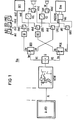
- the drawing 1 shows schematically in a required extent for understanding the invention, a communication system with an analog / digital F ernmelde subscriber station -According to the invention.
- This telecommunication system has a two-wire switching center A-VSt (given, for example, by an extension switching system ESK 10-2 electronic or EMS 300), to which telecommunication subscriber stations each have one with the two-wire connecting lines not shown in detail in FIG the two-wire connecting line connected signaling circuit and a two-wire line branch in.
- a four-wire transmission / reception line branch in particular speech current / hearing current line branch, can be connected to a hybrid circuit, such telecommunication subscriber stations for simultaneous analog communication and digital communication with a frequency multiplexer or demultiplexer for bundling or fanning out one covering the telephone band Analog communication channel and a digital communication channel located above the telephone band can be provided.
- An analog / is connected to the two-wire exchange A-VSt via a two-wire connecting line A1.
- Digital telecommunications subscriber station Tln connected which has a broadband fork circuit G terminating the two-wire connection line A1 and a signaling circuit NSW connected to the two-wire connection line A1; 1 indicates that the signaling circuit can be formed by a customary number switch / alarm clock circuit NSW inserted into the two-wire connecting line A1 or connected to it in a chain connection.
- the telecommunications subscriber station can also be equipped with key dialing, without this being shown in FIG. 1; the telecommunications subscriber station may also have a display for making information visible, which is also not shown in FIG. 1).
- the transmission signal current 2i s supplied by the current source I controlled by the transmission branch VS of the four-wire line VL is divided between the two-wire line Al and the two-wire line termination impedance Z2, R2 to at least approximately equal parts i s ; at the same time, the received signal current i e flows through the two-wire line terminating impedance Z2, R2 via the two-wire line A1 from the remote station - not shown in FIG. 2 and in principle also provided with a signal current source.
- a voltage occurs at the resistor R2 of the two-wire line terminating impedance Z2 + R2, which is composed of a component i e ⁇ R2 proportional to the received signal current and a component i se R2 proportional to the transmit signal current.
- the ohmic resistance R1 lying in series with the signal current source I is only traversed by the transmission signal current 2 * i s , so that here a transmission current proportional voltage 2 * i s * R1 occurs alone.
- Receiving branch VE of the four-wire line VL is acted upon by a received signal corresponding to the voltage occurring between the two connection points e and a and being proportional to the received signal current.
- the parallel connection of the two-wire line impedance Z2, R2 and the current source branch I, R1 can also be used as a feeder for a supply current supplied via the two-wire line A1, so that the signal current source I is supplied by the feed current supplied via the two-wire line A1 if the two-wire line terminating impedance is DC-impermeable.
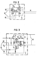
- the signal current source I can be formed by a transistor TI, which is controlled by its control electrode from the transmission branch VS of the four-wire line VS, as illustrated in the drawing in FIG. 3.
- a temperature-stable, voltage-resistant field-effect transistor TI in the example, is as stable as possible an N-channel junction field-effect transistor, preferably with high steepness, is provided, the source resistance of which forms the aforementioned first ohmic resistor R1 with a resistance value of 50 ⁇ , for example.
- the field effect transistor TI can be controlled from the transmission branch VS, for example by a microphone or microphone amplifier circuit, via a coupling element formed with a capacitor of, for example, 10 nF and a resistance of, for example, 1 MQ, so that the supply current is modulated accordingly and thus generates a corresponding transmission signal current becomes.
- the two-wire line impedance Z2, R2 which is impermeable to direct current, consists of the series connection of said second ohmic resistor R2 of, for example, 100 ⁇ and the further impedance Z2 required for further simulation of the two-wire line impedance, depending on the line type, which is advantageously provided by an RC circuit, if necessary, can be formed by an RC chain break circuit, as is also indicated in FIG. 3.
- connection point e of the two resistances R3, R4 which may each have a resistance value of, for example, 100 k ⁇
- the circuit point a °, at which the two ohmic resistors R1 and R2 are directly connected to one another in terms of AC voltage lies in the broadband fork circuit G according to FIG .3 the control path of a transistor TE, in the example of a depletion-type field-effect transistor with an N-channel that works as a simple source follower, from the source resistor of which the received signal for the receive branch VE of the four-wire line VL is picked up via a capacitor.
- a negative feedback operational amplifier can also be provided, without this being shown in the drawing, which is connected to the receiving signal circuit point e with its invating input and to the switching point a with its other input and its output to the Receiving branch VE of the four-wire line VL leads; otherwise any remaining effects of the received signal on the signal current source transistor TI are then avoided.
- an adaptive transversal filter F can be provided parallel to the resistance R3, which feeds the received signal circuit point e to the four-wire line VL an echo compensation signal to further increase the decoupling between the transmitting branch VS and the receiving branch VE. Since it is known in principle (e.g. from FREQUENCY 28 (1974) 5, 118 ... 122 and 155 ... 161) to eliminate transmission-signal-related interference signals occurring in the receive branch of a hybrid circuit by adding or subtracting compensation signals, one is required here such echo cancellation not to be discussed in more detail.
- a circuit element D through which the supply current supplied via the two-wire line flows, is inserted in the supply circuit, at which a local operating voltage U B (for transmit and receive circuits of the four-wire line or for the four-wire branch as a whole and for the hybrid circuit itself) can be tapped.
- This circuit element is formed in the circuit arrangement according to Figure 3 by a zener diode; in deviation from the illustration in FIG. 3, the zener diode can also be replaced by a circuit which only draws current when the operating voltage U B has reached an operating voltage setpoint.
- the broadband fork circuit G in the transmission line branch VS is an at least one analog communication channel covering the telephone band and one above the telephone band frequency multiplexer MUL bundling lying digital communication channel upstream and in the receive line branch VE connected at least one analog communication channel covering the telephone band and one digital communication channel lying above the telephone band fanning out frequency demultiplexer DEX.
- the frequency multiplexer MUL and the frequency demultiplexer DEX are each shown as a low-pass / high-pass crossover, the low-pass input as or output ae of the frequency multiplexer.
- MUL or demultiplexer DEX forms the analog communication channel input or output and the high-pass input ds or output de forms the digital communication channel input or output.
- the speech current line branch M of the telecommunications subscriber station Tln is connected to the analog communication channel input as of the frequency division multiplexer MUL via switching devices UAS, UM, and the switching current line branch H of the telecommunication is connected to the analog communication channel output ae of the demultiplexer DEX via switching devices UAE, UH -T Participant station connected.
- the output bs of the frequency multiplexer MUL leads to the transmission line branch VS which closes the two-wire connection line AI and effects the separation of the transmission signals of the two transmission directions broadband fork circuit G, the reception line branch VE of which leads to the input be of the frequency demultiplexer DEX.
- the telecommunications subscriber station Tln can first of all (in the switching state of the switching devices UM, UAS; UAE, UH shown in FIG. 1) with the delivery of dialing pulses or reception of ringing current signals when establishing a connection, transmission of analog voice signals in the baseband position during the Existence of a telephone connection as well Loop current interruption when initiating the connection in the usual way participate in the telephone traffic (Analbg telephone operation).
- a digital signal transmission circuit DS for transmitting transmission signal pulses with a substantially above the telephone band, ie. significantly above connected of about 4.8 kHz, lying frequency spectrum of a digital communication terminal DEE leads to the switching means via a UDS the output SSD, which is for example a 64-kbit / s D a tenend réelle can act;
- a digital signal receiving circuit DE for receiving received signal pulses with a frequency spectrum which is also above the telephone band, which in turn is connected via a switchover device UDE to the input esd of said digital communication terminal DEE.
- the digital signal transmission circuit can emit, for example, pseudo-ternary half-step signal pulses, so-called half-bauded AMI (alternate mark inversion) signal pulses, as digital signal pulses having no significant spectrum components in the speech frequency band, for which purpose, as described elsewhere (DE- AS 29 16 576) is, a coded storage and storing instantaneous values of the transmission signal pulses and controlled according to the digital signals supplied to them, which feeds the corresponding instantaneous values in their coded representation to a decoder, which forms the corresponding transmission signal pulses.
- pseudo-ternary half-step signal pulses so-called half-bauded AMI (alternate mark inversion) signal pulses
- AMI alternate mark inversion
- the digital signal receiving circuit DE can contain a regenerator as is known in principle (for example from the Siemens publication "PCM - The Pulse Code Modulation and its Application in Telecommunications", page 15, figure 21) and in which with the aid of a clock extractor, the received bit pulse is derived from the received signal pulses, on the basis of which the decision times are defined at which the amplitude decision about the respective status value of the relevant bit is made in the digital signal receiving circuit DE; Furthermore, the digital signal receiving circuit DE can contain a receiving signal converter to be implemented in the example with a rectifier circuit, which converts the regenerated signals into corresponding AM or PCM signals.
- a regenerator as is known in principle (for example from the Siemens publication "PCM - The Pulse Code Modulation and its Application in Telecommunications", page 15, figure 21) and in which with the aid of a clock extractor, the received bit pulse is derived from the received signal pulses, on the basis of which the decision times are defined at which the amplitude decision about the respective status value of the relevant bit is
- a digital signal transmission circuit DS for transmitting transmission signal pulses at certain times or with a predetermined focus of their frequency spectrum and a digital signal reception circuit DE for receiving reception signal pulses at other times or with a different focus of their frequency spectrum;
- the transmit bit clock can, as is suggested elsewhere (DE-AS 29 21 019), be derived from the receive bit clock and be phase-shifted by half a bit period. Further details regarding a digital signal transmission circuit DS and reception circuit DE contained in the analog / digital telecommunications subscriber station Tln according to FIG need not be explained here, however, since this is not necessary to understand the invention.
- the multiplexer MUL can advantageously be reduced to a simple merging circuit, in deviation from the illustration in FIG. 1. while the demultiplexer DEX is formed by a high-pass / low-pass crossover, as shown in FIG.
- the switching devices UAS, UAE are switched from the switching state shown in FIG. 1 to the opposite switching state, then in the analog / digital telecommunications subscriber station Tln according to FIG. 1 with the analog communication input as of the frequency multiplexer.
- MUL the output sld and connected to the analog communication channel output ae of the frequency demultiplexer DEX the input eld of a telephone channel modem MODEM belonging to a (slow) data terminal Dee, for example the telephone channel modem contained in a HF 1048 bright remote copier.
- the switching devices UM, UDS are the switching devices UM, UDS; If UDE, UH is switched from the switching state shown in FIG. 1 to the opposite switching state, then on the transmission side the speech current line branch M of the telecommunications subscriber station Tln according to FIG. 1 is given via the switchover device UM with, for example, a delta or pulse code modulator Voice signal coder CO connected, which in turn is connected via the switching device UDS to the digital signal transmission circuit DS leading to the digital communication channel input ds of the frequency multiplexer MUL for transmitting transmission signal pulses with a frequency spectrum lying above the telephone band; At the receiving end, the digital signal receiving circuit DE connected to the digital communication channel output of the frequency demultiplexer DEX for receiving received signal pulses with a frequency spectrum which is also above the telephone band is connected via the switching device UDE to a speech signal decoder DEC, which via the switching device UH to the hearing current Line branch H of the telecommunications subscriber station Tln leads.
- the telephone communication can also take place only in a corresponding 32 kbit / s subchannel of the 64 kbit / s unit channel carrying AM signals, while a second 32 kbit / s subchannel for a type of communication supporting the telephony communication, for example Teletype, what can be exploited with the help of the digital telephone signals and the Support communication digital signals summarizing or fanning out subchannel multiplexer / demultiplexer can be effected, but need not be pursued here, since this is not necessary to understand the invention.
- Switching the switching devices UDS, UDE; UAS, UAE; UM, UH can, as is also indicated in FIG. 1, be triggered by manual signaling by means of corresponding operating mode switches MHD, ALD, DSD.
- the monitoring circuit is expediently designed so that on the one hand a temporary non-occurrence of F e rn Anlagen digital signal pulses, such as may occur in the course of an undisturbed call connection, is bridged, and on the other hand during prolonged failure of telephone digital signals due to transmission errors - or at '(the now common remote supply of analog F e rnuze subscriber stations unaffected let countries) power failure - switching back operating again on analog telephony - which can be done in the rest-.with the help of the aforementioned mode switch at any time by hand.
- the switching devices which are not required can also be omitted or replaced by a fixed circuit, with reference to the illustration in FIG. 1 in the first example the fast data terminal DEE is also omitted and in the second example the slow data terminal Dee with associated modem MODEM as well as voice signal coder Co and voice signal decoder Dec, while digital signal transmission circuit DS and digital signal reception circuit DE can then be included in the fast data terminal DEE.
- the frequency multiplexer or demultiplexer can then, for example, together with the analog communication channel covering the telephone band, for example from 0.3 kHz to 3.4 kHz, and the one lying above the telephone band, for example a 64 or 80 kbit / s -Unit channel forming and for example approximately from 4 kHz to 80 kHz extending digital communication channel one below the analog communication channel, approximately up to 0.1 kHz digital signal channel and / or one above the digital communication channel, approximately from 0.1 MHz to 1 MHz analog channel or also bundle or fan out one or more additional digital channels.
- the analog communication channel covering the telephone band for example from 0.3 kHz to 3.4 kHz
- the one lying above the telephone band for example a 64 or 80 kbit / s -Unit channel forming and for example approximately from 4 kHz to 80 kHz extending digital communication channel one below the analog communication channel, approximately up to 0.1 kHz digital signal channel and / or one above the digital communication channel, approximately from 0.1 MHz to
- the two-wire connection line A1 connecting the telecommunication subscriber station Tln with the switching center that enables broadband throughput is terminated on the subscriber station side by a broadband fork circuit G, which, as already mentioned above, can decouple the transmission signals of the two transmission directions up to the megahertz range .
- a digital 'telephone subscriber station equipped, for example, according to FIG. 4 with key selection and display, slow data device and video devices, in addition to a - possibly also auxiliary communication-supported - telephone digital operation in the 64 kbit / s digital communication unit channel and a slow data mode, e.g.
- the signals can be transmitted in the baseband position both in the subscriber signal channel and in the analog communication channel covering the telephony band and finally in the 64- or 80-kbit / s digital communication channels above it.
- Video communication is possible in an analog signal channel located above the 64 kbit / s digital communication unit channel, for example moving picture transmission to a video telephone arm with 1 MHz bandwidth.
- the analog / digital telecommunications subscriber station Tln is connected to an input / output of a two-wire switching center A-VSt via the two-wire connecting line A1.
- the telecommunications subscriber station according to the invention can also be connected to a four-wire switching center V-VSt (in FIG. 4), for which purpose the two-wire connection line must then also be terminated at the switching center end by a corresponding broadband fork circuit, as shown in FIG .4 is indicated.
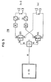
- the transmission branch formed by the voice current line branch M is connected to the one telephone subscriber station Tln I, which is combined with the further telecommunication subscriber station Tln II to form a two-way connection Z1D; with the analog communication channel output ae of the frequency demultiplexer DEX is the the hearing current line branch H forming the receiving branch of the telecommunications subscriber station Tln I is connected.
- the telecommunications subscriber station Tln I can thus participate in the telephone traffic in the usual manner in the analog communication channel covering the telephone band.
- the digital communication channel input ds of the frequency multiplexer MUL is the one through a voice.
- the signal coder CO-guided speech current line branch M formed transmission branch of the second telecommunications subscriber station Tln II of the two-way connection Z1D connected, specifically via a digital signal transmission circuit DS for transmitting transmission signal pulses with a frequency spectrum lying above the telephone band;
- the digital communication channel output de of the frequency demultiplexer DEX is via a digital signal receiving circuit DE for receiving received signal pulses with a frequency spectrum which is also above the telephone band and with the hearing current line branch H of the second telecommunication branch which forms the receiving branch and is conducted via a speech signal decoder DEC.
- Subscriber station Tln II of the two-way connection Z1D connected.
- the telecommunications subscriber station TInII can then participate in the telephony traffic in the digital communication mode, for example 64 kbit / s unit channel, in the digital communication channel above the telephone band.
- the digital communication mode for example 64 kbit / s unit channel
- the relevant statements made above in connection with FIG. 1 or FIG. 4 apply in a corresponding manner, so that here of others Explanations can be dispensed with.
- This transmission branch VS is also symmetrical, i.e. its two output terminals sa, sb conduct the respective transmission signal voltage Us in phase opposition to one another (based on a line symmetry point 0 which leads to a center potential); the internal resistance of the transmission branch VS that occurs between the two output terminals sa, sb or between each output terminal and the line symmetry point 0 may be at least approximately negligible.
- the two inputs -, + one leading to the receiving branch VE of the four-wire line VL are also via two resistors R.
- Operational amplifier V connected; the two resistors may have a high resistance value, so that their influence on the termination of the two-wire line A1 is at least approximately negligible.
- the two inputs -, + of the operational amplifier V are also connected to the two output terminals sb, sa of the transmission branch VS of the four-wire line VL via two resistors 2R twice the resistance value -, + of the operational amplifier V, in the reverse relationship to the assignment to the two-wire line wires a, b.
- the inverting input (-) of the operational amplifier V is connected to its output and the non-inverting input (+) is connected to the line symmetry point 0, in each case via a resistor vR with a resistance value that is v times as large as that of the first-mentioned resistors (R) .
- Operational amplifier output A and line symmetry point 0 form the input of the receiving branch VE of the four-wire line VL.
- reception signal potentials t Ue / 2 which arrive on the two-wire lines a, b (from the far end thereof) and to which the transmission signal potentials ⁇ Us / 2 mentioned above are superimposed there, just a pure reception signal voltage v Ue on, while the transmission signal components arriving at the input terminals of the operational amplifier V are in each case just (at least approximately) compensating each other.
Abstract
Description
Um in einem Fernmeldesystem eine Kommunikation zwischen zwei Fernmeldestellen zu ermöglichen, sind zwischen den Fernmeldestellen Übertragungseinrichtungen erforderlich, die eine hinreichend störungsfreie Signalübertragung in beiden Übertragungsrichtungen ermöglichen, Hierzu kann für jede Übertragungsrichtung eine eigene, ggf. im Multiplexbetrieb auch für eine Mehrzahl gleichzeitig bestehender Verbindungen jeweils zweier Fernmeldestellen mehrfach ausgenutzte Übertragungsleitung vorgesehen sein; ein solcher Vierdrahtbetrieb wird vorzugsweise in höheren Fernmeldenetzebenen vorgesehen sein. In unteren Fernmeldenetzebenen, insbesondere im Bereich der Teilnehmeranschlußleitungen, wird im allgemeinen eine Signalübertragung im Duplexbetrieb über Zweidrahtleitungen durchgeführt. Dabei kann zur Entkopplung der Übertragungssignale der beiden Übertragungsrichtungen eine Signalübertragung im Getrenntlageverfahren vorgesehen sein, indem man für die beiden Übertragungsrichtungen zeitlich und/oder in der Frequenzlage voneinander getrennte Übertragungskanäle vorsieht, und/oder es kann die Trennung der Übertragungssignale der beiden Übertragungsrichtungen mit Hilfe einer die Zweidrahtleitung abschließenden Gabelschaltung in Form einer Brückenschaltung bewirkt werden, die'die Zweidrahtleitung beispielsweise in den vierdrähtigen Teil einer Teilnehmerendstelle (und umgekehrt) überführt.In order to enable communication between two telecommunication points in a telecommunication system, transmission devices are required between the telecommunication points that enable a sufficiently interference-free signal transmission in both transmission directions.Therefore, for each transmission direction, a separate one, possibly in multiplex mode, for two connections that exist simultaneously, can be used Telecommunication points multiple use transmission line may be provided; Such four-wire operation will preferably be provided in higher telecommunications network levels. In lower telecommunications network levels, particularly in the area of the subscriber lines, a signal transmission in duplex mode is generally carried out over two-wire lines. In order to decouple the transmission signals of the two transmission directions, a signal transmission can be provided in the separate position method by providing separate transmission channels for the two transmission directions in terms of time and / or frequency, and / or the transmission signals of the two transmission directions can be separated using a Two-wire line terminating hybrid circuit can be effected in the form of a bridge circuit, which 'transfers the two-wire line, for example, into the four-wire part of a subscriber terminal (and vice versa).
Um eine vollständige Entkopplung des von der Gabel- - schaltung wegführenden Empfangszweiges der Vierdrahtleitung von dem zur Gabelschaltung hinführenden Sendezweig der Vierdrahtleitung zu erzielen, muß die Brückenschaltung abgeglichen sein, wozu sie eine exakte Nachbildung der Eingangsimpedanz der Zweidrahtleitung enthalten muß. In der Praxis enthalten die bei heute im Analog-Fernsprechnetz üblichen Analog-Fernsprechteilnehmerstellen vorgesehenen, die jeweilige Zweidraht-Anschlußleitung in einen vierdrähtigen Sprechstrom-/Hörstrom-Leitungszweig überführenden Analogsignal-Gabelschaltungen eine Kompromißnachbildung, die die (frequenzabhängige) Leitungsimpedanz nur in einem relativ schmalen Frequenzbereich hinreichend genau nachbildet, was indessen für den Analog-Fernsprechverkehr tragbar ist.In order to achieve a complete decoupling of the receiving branch of the four-wire line leading away from the hybrid circuit from the transmitting branch of the four-wire line leading to the hybrid circuit, the bridge circuit must be balanced, for which purpose it must contain an exact replica of the input impedance of the two-wire line. In practice, the analog telephone subscriber stations provided in today's analog telephone network, which convert the respective two-wire connection line into a four-wire speech current / hearing current line branch, contain a compromise replica that only reduces the (frequency-dependent) line impedance in a relatively narrow frequency range sufficiently replicates what is portable for analog telephone traffic.
Neuere Entwicklungen der Fernmeldetechnik führen zu Digital-Fernmeldesystemen, die für Fernsprechteilnehmer eine Wandlung der Sprachsignale in digitale Signale (und umgekehrt) bereits in der Teilnehmerstelle vorsehen und in denen über Digital-Vierdraht-Vermittlungsstellen Digital-Fernsprechverbindungen in einheitlichen Kommunikationskanälen mit einer Bitrate von vorzugsweise 64 kbit/s (je Übertragungsrichtung) aufbaubar sind, wobei außerhalb ("out-slot") dieses 64-kbit/s-Kommunikations-Kanals eine Signalisierungsverbindung für eine sogenannte "out-slot"-Signalisierung in einem zusätzlichen Signalkanal (Teilnehmersignalkanal) mit einer Bitrate von beispielsweise 8 kbit/s (je Übertragungsrichtung) ständig bestehen kann (ISS'79, 773, 777; telcom report 2(1979)4, 254, 259). Außer Sprache können auch Texte, Daten und Bilder übertragen werden; eine solche Übertragung und Vermittlung (Übermittlung) von Digitalsignalen ist in einem zukünftigen dienstintegrierten Fernmeldenetz (ISDN) zu erwarten.Recent developments in telecommunications technology have led to digital telecommunications systems that already convert voice signals into digital signals (and vice versa) for subscribers at the subscriber station and in which digital-four-wire exchanges use digital telephony connections in uniform communication channels with a bit rate of preferably 64 kbit / s (depending on the transmission direction) can be set up, with outside ("out-slot") of this 64 kbit / s communication channel a signaling connection for a so-called "out-slot" signaling in an additional signal channel (subscriber signal channel) with a Bit rate of, for example, 8 kbit / s (for each transmission direction) can constantly exist (ISS'79, 773, 777; telcom report 2 (1979) 4, 254, 259). In addition to voice, texts, data and images can also be transmitted; such a transmission and switching (transmission) of digital signals is in a future integrated telecommunications network (ISDN) can be expected.
Gegenwärtig und in naher Zukunft werden indessen sowohl für Orts-Vermittlungsstellen als auch für Nebenstellenanlagen noch die heute im Analog-Fernsprechnetz üblichen Zweidraht-Vermittlungsstellen eingesetzt sein, an die über Zweidraht-Anschlußleitungen jeweils mit einer im Zweidrahtleitungszweig liegenden Signalisierungsschaltung und einer den Zweidrahtleitungszweig abschließenden Analogsignal-Gabelschaltung versehene Anälog-Fernsprech-Teilnehmerstellen angeschlossen sind. Bei Einführung und weiterer Vervollständigung eines dienstintegrierten Digitalnetzes wird daher bereits eine große Anzahl solcher Fernmeldesysteme im Rahmen des herkömmlichen Analog-Fernmeldenetzes in Betrieb sein; dabei in zweckmäßiger Weise auch die Vorteile digitaler Kommunikationsverfahren ausnutzen zu können, zeigt die Erfindung einen Weg.At present and in the near future, however, the two-wire exchanges common today in the analog telephone network will still be used both for local exchanges and for private branch exchanges, to which two-wire connecting lines each have a signaling circuit located in the two-wire line branch and an analog signal terminating the two-wire line branch. Dual-circuit analog telephone subscriber stations are connected. With the introduction and further completion of an integrated digital network, a large number of such telecommunication systems will therefore already be in operation within the framework of the conventional analog telecommunication network; To be able to utilize the advantages of digital communication methods in an expedient manner, the invention shows a way.
In diesem Zusammenhang ist es bereits (aus NTF 73, 1980, S.36...40) bekannt, dem Analog-Fernsprech-Kanal einer an eine Zweidraht-Anschlußleitung angeschlossenen Fernmelde-Teilnehmerstelle einen oberhalb des Fernsprechbandes liegenden 96 kbit/s-Digital-Kommunikations-Kanal zu überlagern, indem die Zweidraht-Anschlußleitung durch eine Frequenzweiche abgeschlossen wird, an deren Tiefpaßzweig das übliche Analog-Fernsprechgerät angeschlossen ist und an deren Hochpaßzweig über eine adaptive Gabelschaltung in Form einer mit einem Echokompensator verbundenen Brückenschaltung eine Digitalsignal-Sende-tEmpfangs-Schaltung angeschlossen ist. Eine solche Fernmelde- Teilnehmerstelle erscheint insofern als relativ aufwendig, als neben einer als Frequenzmultiplexer/-demultiplexer wirkenden Frequenzweiche sowohl im Tiefpaßzweig als auch im Hochpaßzweig jeweils eine durch eine Brückenschaltung zu realisierende Gabelschaltung vorgesehen sein muß, wobei die im Hochpaßzweig liegende, an sich zu schmalbandige Brückenschaltung durch einen Echokompensator ergänzt sein muß.In this connection it is already (from NTF 73, 1980, p.36 ... 40) are known, the analog telephone channel of a connected to a two-wire subscriber line telecommunications subscriber station kbit / s a rnsprechbandes above the F e lie 96 -Digital communication channel superimposed by the two-wire connection line is terminated by a crossover, to the low-pass branch of the conventional analog telephone set is connected and to the high-pass branch via an adaptive hybrid circuit in the form of a bridge circuit connected to an echo canceller, a digital signal transmission -tReception circuit is connected. Such a telecommunications subscriber station appears to be relatively expensive in that, in addition to a crossover acting as a frequency multiplexer / demultiplexer, both in the low-pass branch as well as in the high-pass branch a fork circuit to be realized by a bridge circuit must be provided, the bridge circuit located in the high-pass branch, which is too narrow-band, must be supplemented by an echo canceller.
Die Erfindung zeigt demgegenüber einen Weg zu einer weniger aufwendigen Fernmelde-Teilnehmerstelle für Analog-Kommunikation im Fernsprech-Kanal und Digital-Kommunikation in einem darüberliegenden Digitalkommunikations-Kanal.In contrast, the invention shows a way to a less complex telecommunications subscriber station for analog communication in the telephone channel and digital communication in an overlying digital communication channel.
Die Erfindung betrifft eine an eine Zweidraht-Anschlußleitung anschließbare Fernmelde-Teilnehmerstelle mit einem Frequenzmultiplexer bzw. -demultiplexer zur Bündelung bzw. Auffächerung eines das Fernsprechband überdeckenden Analog-Kommunikations-Kanals und eines oberhalb des Fernsprechbandes liegenden Digital-Kommunikations-Kanals und mit einer einen Zweidrahtleitungszweig in einen vierdrähtigen Sende-/Empfangs-Leitungszweig, insbesondere Sprechstrom-/Hörstrom-Leitungszweig, überführenden Gabelschaltung; diese Fernmelde-Teilnehmerstelle ist erfindungsgemäß dadurch gekennzeichnet, daß die Zweidraht-Anschlußleitung durch eine Breitbandgabelschaltung abgeschlossen ist, der im Sende-Leitungszweig ein zumindest den das Fernsprechband überdeckenden Analog-Kommunikations-Kanal und den oberhalb des Fernsprechbandes liegenden Digital-Kommunikations-Kanal bündelnder Frequenzmultiplexer vorgeschaltet und im Empfangs-Leitungszweig ein zumindest den das Fernsprechband überdeckenden Analog-Kommunikations-Kanal und den oberhalb des Fernsprechbandes liegenden Digital-Kommunikations-Kanal auffächernder Frequenzdemultiplexer nachgeschaltet ist; in weiterer Ausgestaltung der Erfindung kann der Frequenz- ..multiplexer bzw. -demultiplexer zusammen mit dem das Fernsprechband überdeckenden (beispielsweise etwa von 0,3 kHz bis 3,4 kHz reichenden) Analog-Kommunikations- Kanal und dem oberhalb des Fernsprechbandes liegenden (beispielsweise etwa von 4,5 bis 80 kHz reichenden) Digital-Kommunikationskanal einen unterhalb des Analog- Kommunikations-Kanals liegenden (beispielsweise etwa bis 0,1 kHz reichenden) Digitalsignalkanal und/oder einen oberhalb des Digital-Kommunikations-Kanals liegenden (beispielsweise etwa von 0,1 bis 1 MHz reichenden) Analogkanal oder auch Digitalkanal bündeln bzw. auffächern.The invention relates to a telecommunications subscriber station that can be connected to a two-wire connecting line and has a frequency multiplexer or demultiplexer for bundling or fanning out an analog communication channel covering the telephone band and a digital communication channel lying above the telephone band and with a two-wire line branch hybrid circuit transferring into a four-wire transmission / reception line branch, in particular speech current / hearing current line branch; This telecommunications subscriber station is characterized in that the two-wire connection line is terminated by a broadband fork circuit, which upstream in the transmission line branch connects at least the analog communication channel covering the telephone band and the frequency multiplexer bundling the digital communication channel lying above the telephone band and a frequency demultiplexer fanning out at least the analog communication channel covering the telephone band and the digital communication channel lying above the telephone band is connected in the receive line branch; in another embodiment of the invention, the frequency can ..multiplexer or demultiplexer together with the telephone band covering (for example, about from 0.3 kHz to 3.4 kHz ranging) analog communication channel and the rnsprechbandes above the lying F e (for example about 4.5 to 80 kHz range) digital communication channel one below the analog communication channel (for example about 0.1 kHz range) digital signal channel and / or one above the digital communication channel (for example about bundle or fan out the analog channel or digital channel ranging from 0.1 to 1 MHz.
Die Erfindung macht sich dabei besonders den Umstand zunutze, daß aufgrund neuerer fernmeldetechnischer Ent- . wicklungen als für die Anwendung im Rahmen der Erfindung besonders geeignet eine relativ einfache und zugleich sehr breitbandige übertragerfreie Gabelschaltung zur Verfügung steht, in der parallel zur Serienschaltung einer vom Sende-Leitungszweig gesteuerten Stromquelle und eines Widerstandes die aus einem zweiten Widerstand und einer Restimpedanz gebildete Zweidrahtleitungs-Abschlußimpedanz geschaltet ist und der durch die beiden Widerstände gebildeten Serienschaltung die Serienschaltung zweier weiterer Resistanzen parallelgeschaltet.ist, wobei der Empfangs-Leitungszweig durch die zwischen dem Verbindungspunkt der beiden Resistanzen und dem Verbindungspunkt der beiden Widerstände auftretende Spannung gesteuert wird; es wird damit eine sehr breitbandige, bis hin zum Megahertzbereich wirksame Entkopplung der Übertragungssignale der beiden Übertragungsrichtungen erreicht.The invention makes particular use of the fact that due to newer telecommunication ent. a relatively simple and at the same time very broadband transformer-free hybrid circuit is available, in which, parallel to the series connection, a current source and a resistor controlled by the transmission line branch, the two-wire line line formed from a second resistor and a residual impedance is particularly suitable for use in the context of the invention. Terminating impedance is connected and the series circuit formed by the two resistors is connected in series with two further resistances, the receiving line branch being controlled by the voltage occurring between the connection point of the two resistances and the connection point of the two resistors; a very broadband decoupling of the transmission signals of the two transmission directions, which is effective up to the megahertz range, is thus achieved.
Die Erfindung bringt den Vorteil mit sich, mit nur geringem schaltungstechnischem Aufwand einer Fernmelde-Teilnehmerstelle in beiden Übertragungsrichtungen jeweils Analog-Kommunikation im (3-kHz-)Fernsprech-Kanal und Digital-Kommunikation in einem darüberliegenden Digital-Kommunikations-Kanal , beispielsweise einem 64- oder 80-kbit/s-Kanal, auch schon im Rahmen eines herkömmlichen Analog-Fernmeldenetzes zu ermöglichen und darüberhinaus auch einen Weg zu einer Digital kommunikation in einem unterhalb des Fernsprech-Bandes liegenden Teilnehmersignalkanal und/oder zu einer Analog-Kommunikation, insbesondere Video-Kommunikation, in einem oberhalb des Digital-Kommunikations-Kanals liegenden Analogkanal zu eröffnen. Von Vorteil ist in diesem Zusammenhang insbesondere auch, daß aufgrund zweckentsprechender Wahl von Leitungscode und Modulationsart, so daß sich Digitalsignal-Basisband und Analogsignal-Basisband sowie ggf. Teilnehmersignalisierungs-Basisband zumindest nicht merklich überschneiden, der Multiplexer zu einer einfachen Kombinationsschaltung reduziert sein kann.The invention has the advantage that analog communication in the (3 kHz) telephone channel and digital communication in an overlying digital communication channel, for example a 64 - or 80 kbit / s channel, even within the framework of a conventional analog telecommunications network and beyond also to open a path to digital communication in a subscriber signal channel lying below the telephone band and / or to analog communication, in particular video communication, in an analog channel lying above the digital communication channel. In this context, it is particularly advantageous that the multiplexer can be reduced to a simple combination circuit due to the appropriate choice of line code and type of modulation, so that the digital signal baseband and analog signal baseband as well as possibly subscriber signaling baseband do not overlap at least noticeably.
In weiterer Ausgestaltung der Erfindung kann mit dem Analogkommunikationskanal-Eingang des Frequenzmultiplexers der Sprechstrom-Leitungszweig und mit dem Analogkommunikationskanal-Ausgang des Frequenzmultiplexers der Hörstrom-Leitungszweig der Fernmelde-Teilnehmerstelle verbunden sein, während mit dem Digitalkommunikationskanal-Eingang des Frequenzmultiplexers eine einem Digitalkommunikations-Endgerät zugehörige Digitalsignal-Sendeschaltung zum Aussenden von Sendesignalimpulsen mit einem im wesentlichen oberhalb des Fernsprechbandes liegenden Frequenzspektrum und mit dem Digitalkommunikationskanal-Ausgang des Frequenzdemultiplexers eine einem Digitalkommunikations-Endgerät zugehörige Digitalsignal-Empfangsschaltung zum Empfang von Empfangssignalimpulsen mit einem ebenfalls oberhalb des Fernsprechbandes liegenden Frequenzspektrum verbunden ist. Eine solche Konfiguration ermöglicht gleichzeitig mit einem normalen Analog-Fernsprech-Betrieb eine Kommunikation zwischen (schnellen) Digitalkommunikations-Endgeräten beispielsweise mit einem Datenfluß von 64 oder 80 kbit/s.In a further embodiment of the invention, the speech current line branch can be connected to the analog communication channel input of the frequency multiplexer and the audio current line branch of the telecommunication subscriber station can be connected to the analog communication channel output of the frequency multiplexer, while one belonging to a digital communication terminal is connected to the digital communication channel input of the frequency multiplexer Digital signal transmission circuit for transmitting transmission signal pulses with a frequency spectrum lying essentially above the telephone band and with the digital communication channel output of the frequency demultiplexer a digital signal reception circuit associated with a digital communication terminal for receiving reception signal pulses is connected to a frequency spectrum which is also above the telephone band. Such a configuration enables communication between (fast) digital communication terminals, for example with a data flow of 64 or 80 kbit / s, at the same time as normal analog telephone operation.
;Alternativ dazu kann auch mit dem Analogkommunikationskanal-Eingang des Frequenzmultiplexers der Ausgang und mit dem Analogkommunikations-Ausgang des Frequenzdemultiplexers der Eingang eines einem Datenendgerät zugehörigen Fprnsprechkanalmodems verbunden sein, während der Sprechstrom-Leitungszweig der Fernmelde-Teilnehmerstelle über einen Coder und eine Digitalsignal-Sendeschaltung zum Aussenden von Sendesignalimpulsen mit einem oberhalb des Fernsprechbandes liegenden Frequenzspektrum mit dem Digitalkommunikationskanal-Eingang des Frequenzmultiplexers und der Digitalkommunikationskanal-Ausgang des Frequenzdemultiplexers über eine Digitalsignal-Empfangsschaltung zum Empfang von Empfangssignalimpulsen mit einem ebenfalls oberhalb des Fernsprechbandes liegenden Frequenzspektrum und einen Decoder mit dem Hörstrom-Leitungszweig der Fernmelde-Teilnehmerstelle verbunden ist; dies ermöglicht gleichzeitig Digital-Fernsprechen beispielsweise in einem 64-kbit/s-Kommunikationskanal und (langsame) Datenübertragung im Analog-Fernsprech-kanal.; Alternatively, the output and. Can also be used with the analog communication channel input of the frequency multiplexer to the analog communication output of the Frequenzdemultiplexers the input of a data terminal associated F p be rnsprechkanalmodems connected, while the speech current line branch of the telecommunications subscriber station via a coder and a digital signal transmission circuit for transmitting transmission signal pulses having a lying above the telephone band frequency spectrum by the digital communication channel -Input of the frequency multiplexer and the digital communication channel output of the frequency demultiplexer is connected via a digital signal receiving circuit for receiving received signal pulses with a frequency spectrum which is also above the telephone band and a decoder is connected to the hearing current line branch of the telecommunications subscriber station; this simultaneously enables digital telephony, for example in a 64 kbit / s communication channel, and (slow) data transmission in the analog telephony channel.
Beide Alternativen können auch dahingehend weitergebildet sein, daß die genannten Verbindungen zu den beiden FrequenzmUltiplexer-Eingängen bzw.von den beiden Frequenzdemultiplexer-Ausgängen jeweils über durch manuelle Signalgabe und/oder nach Maßgabe eines Empfanges von Digitalsignalen umschaltbare Umschalteeinrichtungen verlaufen, was es ermöglicht, ggf. auch wahlweise von der einen auf die andere Betriebsart umzuschalten.Both alternatives can also be further developed in such a way that the connections mentioned to the two frequency multiplexer inputs or from the two frequency demultiplexer outputs each run via switching devices which can be switched over by manual signaling and / or in accordance with a reception of digital signals, which makes it possible, if necessary alternatively switch from one to the other operating mode.
In weiterer Ausgestaltung der Erfindung kann auch mit dem Analogkommunikationskanal-Eingang des Frequenzmultiplexers der Sendezweig, insbesondere Sprechstrom-Leitungszweig, und mit dem Analogkommunikationskanal-Ausgang des Frequenzdemultiplexers der Empfangszweig, insbesondere Hörstrom-Leitungszweig, der mit einer weiteren Fernmelde-Teilnehmerstelle zu einem Zweieranschluß zusammengefaßten Fernmelde- Teilnehmerstelle verbunden sein, während der Sendezweig, insbesondere über einen Coder geführte Sprechstrom-Leitungszweig, der zweiten Fernmelde-Teilnehmerstelle über eine Digitalsignal-Sendeschaltung zum Aussenden von Sendesignalimpulsen mit einem oberhalb des Fernsprechbandes liegenden Frequenzspektrum mit dem Digital- kommunikationskanal-Eingang des Frequenzmultiplexers und der Digitalkommunikationskanal-Ausgang des Frequenzdemultiplexers über eine Digitalsignal-Empfangsschaltung zum Empfang von Empfangssignalimpulsen mit einem ebenfalls oberhalb des Fernsprechbandes liegenden Frequenzspektrum mit dem Empfangszweig, insbesondere über einen Decoder geführten Hörstrom-Leitungszweig, der zweiten Fernmelde- Teilnehmerstelle des Zweieranschlusses verbunden ist; die Erfindung ermöglicht damit eine moderne Realisierung eines Zweieranschlusses, die zugleich dem einen Zweieranschluß-Teilnehmer Digital-Kommunikationsmöglichkeiten auch schon im Rahmen eines herkömmlichen Analog-Fernmeldenetzes erschließt.In a further embodiment of the invention, the transmission branch, in particular voice current line branch, can also be used with the analog communication channel input of the frequency multiplexer, and the reception branch, in particular audio current line branch, with the analog communication channel output of the frequency demultiplexer, the telecommunication combined with a further telecommunications subscriber station to form a two-way connection - the subscriber station must be connected during the transmission branch, in particular via a coder-operated speech current line branch, the second telecommunications subscriber station via a digital signal transmission circuit for transmitting transmission signal pulses with a frequency spectrum above the telephone band with the digital communication channel input of the frequency multiplexer and the digital communication channel output of the frequency demultiplexer via a digital signal input Receiving circuit for receiving received signal pulses with a frequency spectrum likewise above the telephone band is connected to the receiving branch, in particular via a hearing current line branch guided via a decoder, to the second telecommunications subscriber station of the two-way connection; The invention thus enables a modern implementation of a two-way connection, which at the same time opens up digital communication options to one two-way subscriber even within the framework of a conventional analog telecommunications network.
Bei allen diesen Alternativen kann ferner in weiterer Ausgestaltung der Erfindung eine gescrambelte Pseudoternär-Halbschritt-Signalimpulse (AMI-Signalimpulse) aussendende Digitalsignal-Sendeschaltung und/oder eine solche - keine wesentlichen Spektrumsanteile im Sprachfrequenzband aufweisenden - Signalimpulse empfangende Digitalsignal-Empfangsschaltung vorgesehen sein; es kann auch eine Digitalsignal-Sendeschaltung zum Aussenden von Sendesignalimpulsen zu bestimmten Zeitpunkten bzw. mit einem vorgegebenen Schwerpunkt ihres Frequenzspektrums und eine Digitalsignal-Empfangsschaltung zum Empfangen von Empfangssignalimpulsen zu anderen Zeitpunkten bzw. mit einem anderen Schwerpunkt ihres Frequenzspektrums vorgesehen sein, was eine weitere Erhöhung der Entkopplung mit sich bringt.In all of these alternatives, a digital signal transmission circuit emitting scrambled pseudo-ternary half-step signal pulses (AMI signal pulses) and / or such a digital signal reception circuit receiving signal impulses that have no significant spectrum components in the voice frequency band can be provided; it can also be provided a digital signal transmission circuit for transmitting transmission signal pulses at certain times or with a predetermined focus of their frequency spectrum and a digital signal reception circuit for receiving reception signal pulses at other times or with a different focus of their frequency spectrum, which further increases the Decoupling.
Die Fernmelde-Teilnehmerstelle kann in weiterer Ausgestaltung der Erfindung über die Zweidraht-Anschlußleitung an einen Eingang/Ausgang einer Zweidraht-Vermittlungsstelle angeschlossen sein und sich damit die Breitbandigkeit der Koppelpunktschalter heute üblicher Zweidraht-Vermittlungen und ebenso der heute installierten Zweidraht-Ortsverbindungsleitungen zunutze machen, so daß bei entsprechender Breitbandigkeit auch der Teilnehmeranschlußschaltungen, wie sie bei sog..Drossel- speisung gegeben ist, auch in einem herkömmlichen Analog-Fernmeldenetz unter Weiterbenutzung der darin üblichen Signalisierungs- und Verbindungsauf- und -abbauverfahren und der übrigen vermittlungstechnischen Leistungsmerkmale, d.h. im Rahmen bereits vorhandener Zweidraht-Vermittlungsstellen und -Nebenstellenanlagen, nicht nur generell die Vorteile digitaler Kommunikationsverfahren, wie z.B. weitgehender Dämpfungsunabhängigkeit, konstanter und ggf. verbesserter Sprachqualität und einfacher Realisierbarkeit verschiedener Kommunikationsformen in einer bestehenden Verbindung (Mischkommunikation), ausgenutzt werden können, sondern dabei beispielsweise neben einem Fernsprech-Analog-Kanal auch ein darunterliegender Teilnehmersignalisierungs- kanal.und ein darüberliegender schneller Datenkanal bereitgestellt werden können. Von Vorteil ist dabei die Vermeidung von Kompatibilitätsproblemen, indem von einer in der angegebenen Weise ausgebildeten und angeschlossenen Ferrmelde-Teilnehmerstelle einerseits Analog-Verbindungen sowohl zu reinen Analog-Fernmeldestellen als auch zu in der vorstehend angegebenen Weise ausgerüsteten Fernmelde-Teilnehmerstellen möglich sind und andererseits Digital-Verbindungen sowohl zu in der angegebenen Weise ausgerüsteten Fernmelde-Teilnehmerstellen als auch zu reinen Digital-Teilnehmerstellen, womit die Möglichkeit gegeben ist, ggf. auch nur einzelne Fernmelde-Teilnehmerstellen einer herkömmlichen Ortsvermittlungsstelle oder Nebenstellenanlage gemäß der Erfindung auszubilden und anzuschließen.In a further embodiment of the invention, the telecommunications subscriber station can use the two-wire connecting line to an input / output of a two-wire switch be connected and thus take advantage of the broadband nature of the cross-point switches of today's conventional two-wire exchanges and also of the two-wire local trunk lines installed today, so that, with appropriate broadband capability, the subscriber line circuits, as is the case with so-called throttle supply, also in one conventional analog telecommunication network while continuing to use the usual signaling and connection setup and clearing procedures and the other switching features, i.e. within the framework of existing two-wire switching centers and private branch exchanges, not only generally the advantages of digital communication methods, such as extensive damping independence, constant and If necessary, improved speech quality and simple feasibility of different forms of communication in an existing connection (mixed communication) can be used, but in this case, for example, in addition to a telephone call alog channel, an underlying subscriber signaling channel and an overlying fast data channel can also be provided. The avoidance of compatibility problems is advantageous in that, from a Ferrmeldeesstellestelle trained and connected in the specified manner, on the one hand analog connections are possible both to pure analogue telecommunications stations and to telecommunication subscriber stations equipped in the manner specified above, and on the other hand digital Connections to telecommunication subscriber stations equipped in the specified manner as well as to purely digital subscriber stations, which gives the possibility of possibly also training and connecting only individual telecommunication subscriber stations of a conventional local exchange or private branch exchange according to the invention.
Anhand der Zeichnungen sei die Erfindung noch näher erläutert.The invention will be explained in more detail with reference to the drawings.
Dabei zeigt
- Fig.1 im Rahmen eines Fernmeldesystems ein Ausführungsbeispiel einer Analog-/Digital-Fernmelde-Teilnehmerstelle gemäß der Erfindung;
- Fig.2 zeigt ein Prinzipschaltbild und
- Fig.3 zeigt schaltungstechnische Einzelheiten einer für die Analog-/Digital-Fernmelde-Teilnehmerstelle gemäß der Erfindung besonders geeigneten Breitbandgabelschaltung.
- Fig.4 und 5 zeigen wiederum im Rahmen eines Fernmeldesystems ein Ausführungsbeispiel einer Analog-/Digital-Fernmelde-Teilnehmerstelle gemäß der Erfindung; und
- Fig.6 zeigt wiederum ein Prinzipschaltbild einer für die Analog-/Digital-Fernmelde-Teilnehmerstelle gemäß der Erfindung besonders geeigneten Breitbandgabelschaltung.
- 1 in the context of a telecommunications system, an embodiment of an analog / digital telecommunications subscriber station according to the invention;
- Fig. 2 shows a block diagram and
- 3 shows circuit-specific details of a broadband fork circuit which is particularly suitable for the analog / digital telecommunications subscriber station according to the invention.
- 4 and 5 again show, in the context of a telecommunications system, an embodiment of an analog / digital telecommunications subscriber station according to the invention; and
- 6 again shows a basic circuit diagram of a broadband fork circuit which is particularly suitable for the analog / digital telecommunications subscriber station in accordance with the invention.
Die Zeichnung Fig.1 zeigt schematisch in einem zum Verständnis der Erfindung erforderlichen Umfange ein Fernmeldesystem mit einer Analog-/Digital-Fernmelde-Teilnehmerstelle -gemäß der Erfindung. Dieses Fernmeldesystems weist eine (z.B. durch eine Nebenstellen-Vermittlungsanlage ESK 10-2 electronic oder EMS 300 gegebene) Zweidraht-Vermittlungsstelle A-VSt auf, an die über in Fig.1 nicht im einzelnen dargestellte Zweidraht-Anschlußleitungen Fernmelde-Teilnehmerstellen jeweils mit einer mit der Zweidraht-Anschlußleitung verbundenen Signalisierungsschaltung und einer einen Zweidrahtleitungszweig in. einen vierdrähtigen Sende-/Empfangs-Leitungszweig, insbesondere Sprechstrom-/Hörstrom-Leitungszweig, überführenden Gabelschaltung angeschlossen sein können, wobei solche Fernmelde-Teilnehmerstellen zur gleichzeitigen Analog-Kommunikation und Digital-Kommunikation mit einem Frequenzmultiplexer bzw. -demultiplexer zur Bündelung bzw. Auffächerung eines das Fernsprechband überdeckenden Analog-Kommunikations-Kanals und eines oberhalb des Fernsprechbandes liegenden Digital-Kommunikations-Kanals versehen sein können. Über eine Zweidraht-Anschlußleitung Al ist an die Zweidraht-Vermittlungsstelle A-VSt eine Analog-/ . Digital-Fernmelde-Teilnehmerstelle Tln angeschlossen, die eine die Zweidraht-Anschlußleitung Al abschließende Breitbandgabelschaltung G sowie eine mit der Zweidraht-Anschlußleitung Al verbundene Signalisierungsschaltung NSW aufweist; in Fig.1 ist dazu angedeutet, daß die Signalisierungsschaltung durch eine übliche, in die Zweidraht-Anschlußleitung Al eingefügte bzw. in Kettenschaltung mit ihr verbundene Nummernschalter-/Wecker-Schaltung NSW gebildet sein kann. (Alternativ dazu kann die Fernmelde-Teilnehmerstelle aber auch mit Tastenwahl'ausgerüstet sein, ohne daß dies in Fig.1 dargestellt ist; die Fernmeldeteilnehmerstelle kann auch ein Display zur Sichtbarmachung von Informationen aufweisen, was ebenfalls in Fig.1 nicht näher dargestellt ist).The drawing 1 shows schematically in a required extent for understanding the invention, a communication system with an analog / digital F ernmelde subscriber station -According to the invention. This telecommunication system has a two-wire switching center A-VSt (given, for example, by an extension switching system ESK 10-2 electronic or EMS 300), to which telecommunication subscriber stations each have one with the two-wire connecting lines not shown in detail in FIG the two-wire connecting line connected signaling circuit and a two-wire line branch in. a four-wire transmission / reception line branch, in particular speech current / hearing current line branch, can be connected to a hybrid circuit, such telecommunication subscriber stations for simultaneous analog communication and digital communication with a frequency multiplexer or demultiplexer for bundling or fanning out one covering the telephone band Analog communication channel and a digital communication channel located above the telephone band can be provided. An analog / is connected to the two-wire exchange A-VSt via a two-wire connecting line A1. Digital telecommunications subscriber station Tln connected, which has a broadband fork circuit G terminating the two-wire connection line A1 and a signaling circuit NSW connected to the two-wire connection line A1; 1 indicates that the signaling circuit can be formed by a customary number switch / alarm clock circuit NSW inserted into the two-wire connecting line A1 or connected to it in a chain connection. (Alternatively, the telecommunications subscriber station can also be equipped with key dialing, without this being shown in FIG. 1; the telecommunications subscriber station may also have a display for making information visible, which is also not shown in FIG. 1).
Bezüglich der Breitbandgabelschaltung G sei an dieser Stelle zunächst ein Blick auf die Zeichnungen Fig.2 und Fig.3 geworfen, die ein Prinzipschaltbild und schaltungstechnische Einzelheiten einer solchen Breitbandgabelschaltung G zeigen:
- Die in Fig.2 im Prinzipschaltbild dargestellte, mit einer den Wellenwiderstand der Zweidrahtleitung Al zumindest angenähert nachbildenden Zweidrahtleitungs-Abschlußimpedanz Z2, R2 versehene Gabelschaltung G zur Verbindung der Zweidrahtleitung Al mit einer den Sendezweig VS und den Empfangszweig VE aufweisenden Vierdrahtleitung VL bei gleichzeitiger Entkopplung der beiden Vierdrahtleitungszweige VS, VE voneinander enthält-zunächst die Reihenschaltung einer Signalstromquelle I, zu deren Steuereingang der Sendezweig VS der Vierdrahtleitung VL führt, und eines ersten ohmschen Widerstandes R1; dieser Reihenschaltung ist die durch die Reihenschaltung eines zweiten ohmschen Widerstandes R2, dessen Widerstandswert zumindest angenähert doppelt so groß wie derjenigen des ersten ohmschen Widerstandes R1 sein mag, und einer weiteren Impedanz Z2 gebildete Zweidrahtleitungs-Abschlußimpedanz parallelgeschaltet. Die beiden einen Klemmen der beiden ohmschen Widerstände R1, R2 sind untereinander und mit der einen Zweidrahtleitungsader a zumindest wechselstrommäßig direkt verbunden, während die beiden anderen Klemmen der beiden ohmschen Widerstände R1, R2 über die Reihenschaltung zweier Resistanzen R3, R4 miteinander verbunden sind, wobei diese beiden Resistanzen von gleicher Größe und zugleich groß gegenüber - dem ersten Widerstand R1 und dem zweiten Widerstand R2 sein mögen. Zwischen dem Verbindungspunkt e der beiden Resistanzen R3, R4 und dem Verbindungspunkt a der beiden Widerstände R1, R2 ist der Empfangszweig VE der Vierdrahtleitung VL angeschlossen.
- The fork circuit G shown in the basic circuit diagram in FIG. 2, provided with a two-wire line terminating impedance Z2, R2 at least approximately simulating the characteristic impedance of the two-wire line Al, for connecting the two-wire line A1 to a four-wire line VL having the transmitting branch VS and the receiving branch VE, with simultaneous decoupling of the two Four-wire line branches VS, VE from one another initially contain the series connection of a signal current source I, to the control input of which the transmission branch VS of the four-wire line VL leads, and a first ohmic resistor R1; this series connection is that due to the series connection of a second ohmic resistor R2, the resistance value of which is at least approximately twice as large as that of the first ohmic resistor R1, and a further impedance Z2 formed two-wire terminating impedance connected in parallel. The two one terminals of the two ohmic resistors R1, R2 are directly connected to one another and to the one two-wire line core a, at least in terms of alternating current, while the two other terminals of the two ohmic resistors R1, R2 are connected to one another via the series connection of two resistors R3, R4, these two resistances of the same size and large at the same time - may be the first resistor R1 and the second resistor R2. The receiving branch VE of the four-wire line VL is connected between the connection point e of the two resistances R3, R4 and the connection point a of the two resistors R1, R2.
In der Schaltungsanordnung nach Fig.2 teilt sich der von der vom Sendezweig VS der Vierdrahtleitung VL her gesteuerten Stromquelle I gelieferte Sendesignalstrom 2is auf die Zweidrahtleitung Al und die Zweidrahtleitungs-Abschlußimpedanz Z2, R2 zu zumindest angenähert gleichen Teilen is auf; zugleich fließt durch die Zweidrahtleitungs-Abschlußimpedanz Z2, R2 der über die Zweidrahtleitung Al von der - in Fig.2 nicht näher dargestellten, im Prinzip ebenfalls mit einer Signalstromquelle versehenen - Gegenstelle her gelieferte Empfangssignalstrom ie. Am Widerstand R2 der Zweidrahtleitungs-Abschlußimpedanz Z2+R2 tritt daher eine Spannung auf, die sich aus einem empfangssignalstromproportionalen Anteil ie·R2 und einem sendesignalstromproportionalen Anteil iseR2 zusammensetzt. Auf der anderen Seite wird der in Serie zur Signalstromquelle I liegende ohmsche Widerstand R1 nur von dem Sendesignalstrom 2·is durchflossen, so daß hier allein eine sendestromproportionale Spannung 2·is·R1 auftritt. Der zwischen dem Verbindungspunkt a der beiden Widerstände R1, R2 und dem Verbindungspunkt e der beiden Resistanzen R3, R4 angeschlossene Empfangszweig VE der Vierdrahtleitung VL wird mit einem der zwischen den beiden Verbindungspunkten e und a auftretenden, dem Empfangssignalstrom proportionalen Spannung entsprechenden Empfangssignal beaufschlagt. Dabei ist die gegenseitige Kompensation der an den beiden ohmschen Widerständen R1 und R2 jeweils auftretenden sendesignalstromproportionalen Spannungen nicht daran gebunden, daß, wie zuvor zunächst angenommen, der Widerstandswert-des zweiten ohmschen Widerstandes R2 gerade doppelt so groß wie derjenige des ersten ohmschen Widerstandes R1 ist und daß der Widerstandswert der Resistanz R3 gerade gleich demjenigen der Resistanz R4 ist; es genügt vielmehr, daß zumindest angenähert R2·R3 = 2·R1·R4 ist, wobei die Widerstandswerte der Resistanzen R3 und R4 groß gegenüber den Widerstandswerten der Widerstände R1 und R2 sein sollten, sodaß ein Einfluß des Empfangssignalstroms ie über die Resistanzen R3, R4 auf die Sendesignalstromquelle I zu vernachlässigen ist.In the circuit arrangement according to FIG. 2, the transmission signal current 2i s supplied by the current source I controlled by the transmission branch VS of the four-wire line VL is divided between the two-wire line Al and the two-wire line termination impedance Z2, R2 to at least approximately equal parts i s ; at the same time, the received signal current i e flows through the two-wire line terminating impedance Z2, R2 via the two-wire line A1 from the remote station - not shown in FIG. 2 and in principle also provided with a signal current source. A voltage occurs at the resistor R2 of the two-wire line terminating impedance Z2 + R2, which is composed of a component i e · R2 proportional to the received signal current and a component i se R2 proportional to the transmit signal current. On the other hand, the ohmic resistance R1 lying in series with the signal current source I is only traversed by the transmission signal current 2 * i s , so that here a transmission current proportional voltage 2 * i s * R1 occurs alone. The one connected between the connection point a of the two resistors R1, R2 and the connection point e of the two resistances R3, R4 Receiving branch VE of the four-wire line VL is acted upon by a received signal corresponding to the voltage occurring between the two connection points e and a and being proportional to the received signal current. The mutual compensation of the transmission signal current proportional voltages occurring at the two ohmic resistors R1 and R2 is not tied to the fact that, as previously assumed, the resistance value of the second ohmic resistor R2 is just twice as large as that of the first ohmic resistor R1 and that the resistance value of the resistance R3 is exactly the same as that of the resistance R4; it is rather sufficient that at least approximately R2 * R3 = 2 * R1 * R4, the resistance values of the resistances R3 and R4 should be large compared to the resistance values of the resistors R1 and R2, so that an influence of the received signal current i e via the resistances R3, R4 on the transmission signal current source I is negligible.
Die Parallelschaltung von Zweidrahtleitungs-AbschluBimpedanz Z2, R2 und Stromquellenzweig I, R1 kann bei gleichstromundurchlässiger Zweidrahtleitungs-Abschlußimpedanz auch als Speiseweiche für einen über die Zweidrahtleitung Al zugeführten Speisestrom ausgenutzt werden, so daß die Signalstromquelle I von dem über die Zweidrahtleitung Al zugeführten Speisestrom durchflossen wird. Dabei kann die Signalstromquelle I durch einen an seiner Steuerelektrode vom Sendezweig VS der Vierdrahtleitung VS her gesteuerten, speisestromdurchflossenen Transistor TI gebildet sein, wie dies die Zeichnung Fig.3 verdeutlicht. Als Signalstromquelle ist in der Breitbandgabelschaltung G nach Fig.3 ein tunlichst temperaturstabiler, spannungsfester Feldeffekttransistor TI, im Beispiel ein N-Kanal-Sperrschicht-Feldeffekttransistor vorzugsweise mit hoher Steilheit, vorgesehen, dessen Source-Widerstand den genannten ersten ohmschen Widerstand R1 mit einem Widerstandswert von beispielsweise 50 Ω bildet. Über ein mit einem Kondensator von beispielsweise 10 nF und einem Widerstand von z.B. 1 MQ gebildetes Koppelglied kann der Feldeffekttransistor TI vom Sendezweig VS her, beispielsweise von einer Mikrophon- oder Mikrofonverstärkerschaltung, gesteuert werden, so daß der Speisestrom entsprechend moduliert und damit ein entsprechender Sendesignalstrom erzeugt wird.The parallel connection of the two-wire line impedance Z2, R2 and the current source branch I, R1 can also be used as a feeder for a supply current supplied via the two-wire line A1, so that the signal current source I is supplied by the feed current supplied via the two-wire line A1 if the two-wire line terminating impedance is DC-impermeable. In this case, the signal current source I can be formed by a transistor TI, which is controlled by its control electrode from the transmission branch VS of the four-wire line VS, as illustrated in the drawing in FIG. 3. As the signal current source in the broadband fork circuit G according to FIG. 3, a temperature-stable, voltage-resistant field-effect transistor TI, in the example, is as stable as possible an N-channel junction field-effect transistor, preferably with high steepness, is provided, the source resistance of which forms the aforementioned first ohmic resistor R1 with a resistance value of 50 Ω, for example. The field effect transistor TI can be controlled from the transmission branch VS, for example by a microphone or microphone amplifier circuit, via a coupling element formed with a capacitor of, for example, 10 nF and a resistance of, for example, 1 MQ, so that the supply current is modulated accordingly and thus generates a corresponding transmission signal current becomes.
Die gemäß Fig.3 gleichstromundurchlässige Zweidrahtleitungs-Abschlußimpedanz Z2, R2 besteht aus der Reihenschaltung des genannten zweiten ohmschen Widerstandes R2 von beispielsweise 100Ω und der zur weiteren Nachbildung des Zweidrahtleitungs-Wellenwiderstandes jeweils nach Leitungstyp erforderlichen weiteren Impedanz Z2, die vorteilhaft durch eine RC-Schaltung, ggf. durch eine RC-Kettenbruchschaltung, gebildet sein kann, wie dies auch in Fig.3 angedeutet ist. Zwischen dem Verbindungspunkt e der beiden Resistanzen R3, R4, die jeweils einen Widerstandswert von beispielsweise 100 kΩ aufweisen mögen, und dem Schaltungspunkt a°, an dem die beiden ohmschen Widerstände R1 und R2 wechselspannungsmäßig direkt miteinander verbunden sind, liegt in der Breitbandgabelschaltung G gemäß Fig.3 die Steuerstrecke eines Transistors TE, im Beispiel eines als einfacher Sourcefolger arbeitenden Verarmungs-IG-Feldeffekttransistors mit N-Kanal, an dessen Source-Widerstand über einen Kondensator das Empfangssignal für den Empfangszweig VE der Vierdrahtleitung VL abgenommen wird. Alternativ zum Transistor TE kann auch, ohne daß dies in der Zeichnung noch dargestellt ist, ein gegengekoppelter Operationsverstärker vorgesehen sein, der mit seinem invatierenden Eingang am Empfangssignalschaltungspunkt e und mit seinem anderen Eingang am Schaltungspunkt a liegt und dessen Ausgang zu dem Empfangszweig VE der Vierdrahtleitung VL führt; dabei sind dann sonst etwa noch verbleibende Rückwirkungen des Empfangssignals auf den Signalstromquellentransistor TI vermieden.3, the two-wire line impedance Z2, R2, which is impermeable to direct current, consists of the series connection of said second ohmic resistor R2 of, for example, 100Ω and the further impedance Z2 required for further simulation of the two-wire line impedance, depending on the line type, which is advantageously provided by an RC circuit, if necessary, can be formed by an RC chain break circuit, as is also indicated in FIG. 3. Between the connection point e of the two resistances R3, R4, which may each have a resistance value of, for example, 100 kΩ, and the circuit point a °, at which the two ohmic resistors R1 and R2 are directly connected to one another in terms of AC voltage, lies in the broadband fork circuit G according to FIG .3 the control path of a transistor TE, in the example of a depletion-type field-effect transistor with an N-channel that works as a simple source follower, from the source resistor of which the received signal for the receive branch VE of the four-wire line VL is picked up via a capacitor. As an alternative to the transistor TE, a negative feedback operational amplifier can also be provided, without this being shown in the drawing, which is connected to the receiving signal circuit point e with its invating input and to the switching point a with its other input and its output to the Receiving branch VE of the four-wire line VL leads; otherwise any remaining effects of the received signal on the signal current source transistor TI are then avoided.
Wie dies auch in Fig.3 angedeutet ist, kann parallel zur Resistanz R3 ein adaptives Transversalfilter F vorgesehen sein, das dem Empfangssignalschaltungspunkt e zur weiteren Erhöhung der Entkopplung zwischen Sendezweig VS und Empfangszweig VE der Vierdrahtleitung VL ein Echokompensationssignal zuführt. Nachdem es (z.B. aus FREQUENZ 28(1974)5, 118...122 und 155...161) prinzipiell bekannt ist,im Empfangszweig einer Gabelschaltung auftretende, sendesignalbedingte Störsignale durch Addition bzw. Subtraktion von Kompensationssignalen zu eliminieren, braucht hier auf eine solche Echokompensation nicht näher eingegangen zu werden.As is also indicated in FIG. 3, an adaptive transversal filter F can be provided parallel to the resistance R3, which feeds the received signal circuit point e to the four-wire line VL an echo compensation signal to further increase the decoupling between the transmitting branch VS and the receiving branch VE. Since it is known in principle (e.g. from FREQUENCY 28 (1974) 5, 118 ... 122 and 155 ... 161) to eliminate transmission-signal-related interference signals occurring in the receive branch of a hybrid circuit by adding or subtracting compensation signals, one is required here such echo cancellation not to be discussed in more detail.
Zwischen den wechselstrommäßig miteinander verbundenen Klemmen des ersten Widerstandes R1 und des zweiten Widerstandes R2 ist in den Speisestromkreis ein von dem über die Zweidrahtleitung zugeführten Speisestrom durchflossenes Schaltungsglied D eingefügt, an welchem eine örtliche Betriebsspannung UB (für Sende- und Empfangsschaltungen der Vierdrahtleitung bzw. für den Vierdrahtzweig insgesamt und für die Gabelschaltung selbst) abgreifbar ist. Dieses Schaltungsglied ist in der Schaltungsanordnung nach Fig.3 durch eine Zenerdiode gebildet; in Abweichung von der Darstellung in Fig.3 kann die Zenerdiode aber auch durch eine Schaltung ersetzt sein, die nur dann Strom aufnimmt, wenn die Betriebsspannung UB einen Betriebsspannungssollwert erreicht hat.Between the AC-connected terminals of the first resistor R1 and the second resistor R2, a circuit element D, through which the supply current supplied via the two-wire line flows, is inserted in the supply circuit, at which a local operating voltage U B (for transmit and receive circuits of the four-wire line or for the four-wire branch as a whole and for the hybrid circuit itself) can be tapped. This circuit element is formed in the circuit arrangement according to Figure 3 by a zener diode; in deviation from the illustration in FIG. 3, the zener diode can also be replaced by a circuit which only draws current when the operating voltage U B has reached an operating voltage setpoint.
Um nun wieder auf Fig.1 zurückzukommen, so ist der Breitbandgabelschaltung G im Sende-Leitungszweig VS ein zumindest einen das Fernsprechband überdeckenden Analog- Kommunikations-Kanal und einen oberhalb des Fernsprechbandes liegenden Digital-Kommunikations-Kanal bündelnder Frequenzmultiplexer MUL vorgeschaltet und im Empfangs-Leitungszweig VE ein zumindest einen das Fernsprechband überdeckenden Analog-Kommunikationskanal und einen oberhalb des Fernsprechbandes liegenden Digital-Kommunikations-Kanal auffächernder Frequenzdemultiplexer DEX nachgeschaltet. In Fig. 1 sind der Frequenzmnltiplexer MUL und der Frequenzdemultiplexer DEX jeweils als Tiefpaß-/Hochpaß-Frequenzweiche dargestellt, wobei der Tiefpaß-Eingang as bzw. -Ausgang ae des Frequenzmultiplexers. MUL bzw. -Demultiplexers DEX den Analogkommunikationskanal-Eingang bzw. -Ausgang bildet und der Hochpaß-Eingang ds bzw. -Ausgang de den Digitalkommunikationskanäl-Eingang bzw. -Ausgang. Über Umschalteeinrichtungen UAS, UM ist mit dem Analogkommunikationskanal-Eingang as des Frequenzmultiplexers MUL der Sprechstrom-Leitungszweig M der Fernmelde-Teilnehmerstelle Tln verbunden, und über Umschalteinrichtungen UAE, UH ist mit dem Analogkommunikationskanal-Ausgang ae des Demultiplexers DEX der Hörstrom-Leitungszweig H der Fernmelde-Teilnehmerstelle Tln verbunden. Der Ausgang bs des Frequenzmultiplexers MUL führt zum Sende-Leitungszweig VS der die Zweidraht-Anschlußleitung AI abschließenden, die Trennung der Übertragungssignale der beiden Übertragungsrichtungen bewirkenden Breitbandgabelschaltung G, deren Empfangs-Leitungszweig VE zu dem Eingang be des Frequenzdemultiplexers DEX führt.To return to FIG. 1, the broadband fork circuit G in the transmission line branch VS is an at least one analog communication channel covering the telephone band and one above the telephone band frequency multiplexer MUL bundling lying digital communication channel upstream and in the receive line branch VE connected at least one analog communication channel covering the telephone band and one digital communication channel lying above the telephone band fanning out frequency demultiplexer DEX. In Fig. 1, the frequency multiplexer MUL and the frequency demultiplexer DEX are each shown as a low-pass / high-pass crossover, the low-pass input as or output ae of the frequency multiplexer. MUL or demultiplexer DEX forms the analog communication channel input or output and the high-pass input ds or output de forms the digital communication channel input or output. The speech current line branch M of the telecommunications subscriber station Tln is connected to the analog communication channel input as of the frequency division multiplexer MUL via switching devices UAS, UM, and the switching current line branch H of the telecommunication is connected to the analog communication channel output ae of the demultiplexer DEX via switching devices UAE, UH -T Participant station connected. The output bs of the frequency multiplexer MUL leads to the transmission line branch VS which closes the two-wire connection line AI and effects the separation of the transmission signals of the two transmission directions broadband fork circuit G, the reception line branch VE of which leads to the input be of the frequency demultiplexer DEX.
Damit kann die Fernmelde-Teilnehmerstelle Tln zunächst einmal (bei dem in Fig.1 dargestellten Schaltzustand der genannten Umschalteinrichtungen UM, UAS; UAE, UH) unter Abgabe von Wahlimpulsen bzw. Empfang von Rufstromsignalen beim Verbindungsaufbau, Übertragung von Analog-Sprachsignalen in Basisbandlage während des Bestehens einer Fernsprechverbindung sowie Schleifenstromunterbrechung beim Auslösen der Verbindung in der üblichen Weise am Fernsprechverkehr teilnehmen (Analbg-Fernsprechbetrieb).Thus, the telecommunications subscriber station Tln can first of all (in the switching state of the switching devices UM, UAS; UAE, UH shown in FIG. 1) with the delivery of dialing pulses or reception of ringing current signals when establishing a connection, transmission of analog voice signals in the baseband position during the Existence of a telephone connection as well Loop current interruption when initiating the connection in the usual way participate in the telephone traffic (Analbg telephone operation).
Mit dem Digitalkommunikationskanal-Eingang ds des Frequenzmultiplexers MUL ist eine Digitalsignal-Sendeschaltung DS zum Aussenden von Sendesignalimpulsen mit einem im wesentlichen oberhalb des Fernsprechbandes, dh. deutlich oberhalb von etwa 4,8 kHz, liegenden Frequenzspektrum verbunden, zu der über eine Umschalteinrichtung UDS der Ausgang ssd eines Digitalkommunikations-Endgerätes DEE führt, bei dem es sich beispielsweise um ein 64-kbit/s-Datenendgerät handeln kann; mit dem Digitalkommunikationskanal-Ausgang de des Frequenzdemultiplexers DEX ist eine Digitalsignal-Empfangsschaltung DE zum Empfang von Empfangssignalimpulsen mit einem ebenfalls oberhalb des Fernsprechbandes liegenden Frequenzspektrum verbunden, die ihrerseits über eine Umschalteinrichtung UDE mit dem Eingang esd des genannten Digitalkommunikations-Endgerätes DEE verbunden ist.With the digital communication channel input ds of the frequency multiplexer MUL is a digital signal transmission circuit DS for transmitting transmission signal pulses with a substantially above the telephone band, ie. significantly above connected of about 4.8 kHz, lying frequency spectrum of a digital communication terminal DEE leads to the switching means via a UDS the output SSD, which is for example a 64-kbit / s D a tenendgerät can act; to the digital communication channel output de of the frequency demultiplexer DEX is connected a digital signal receiving circuit DE for receiving received signal pulses with a frequency spectrum which is also above the telephone band, which in turn is connected via a switchover device UDE to the input esd of said digital communication terminal DEE.
Damit kann (bei dem in Fig.1 dargestellten Schaltzustand der Umschalteinrichtungen UDS, UDE) im Rahmen einer Fernmeldeverbindung mit der in Fig.1 dargestellten Analog-/ Digital-Fernmelde-Teilnehmerstelle Tln neben einer im üblichen-Fernsprech-Kanal (ca. 0,3...3,4 kHz) stattfindenden Analog-Fernsprechkommunikation in einem oberhalb des Fernsprechbandes liegenden Digital-Kommunikations- Kanal, beispielsweise einem 64-kbit/s-Einheitskanal,. auch eine schnelle Daten-Kommunikation (Digital-Datenbetrieb) stattfinden.This means that (in the switching state of the switching devices UDS, UDE shown in FIG. 1) in the context of a telecommunications connection with the analog / digital telecommunications subscriber station Tln shown in FIG. 1, in addition to one in the usual telephone channel (approx. 3 ... 3.4 kHz) analog telephone communication taking place in a digital communication channel above the telephone band, for example a 64 kbit / s standard channel. fast data communication (digital data operation) also take place.
Als keine wesentlichen Spektrumsanteile im Sprachfrequenzband aufweisende Digitalsignalimpulse kann dabei die Digitalsignal-Sendeschaltung beispielsweise Pseudoternär-Halbschritt-Signalimpulse, sogenannte half-bauded-AMI-(alternate-mark-inversion-)Signalimpulse abgeben, wozu sie, wie dies an anderer Stelle (DE-AS 29 16 576) angegeben wird, einen Momentanwerte der Sendesignalimpulse codiert speichernden und nach Maßgabe ihr zugeführter Digitalsignale angesteuerten Festwertspeicher aufweisen kann, der die entsprechenden Momentanwerte in ihrer codierten Darstellung einem Decoder zuführt, welcher daraus die entsprechenden Sendesignalimpulse bildet. Zum Empfang entsprechender Empfangssignalimpulse kann die Digitalsignal-Empfangsschaltung-DE einen Regenerator enthalten, wie er prinzipiell (beispielsweise aus der Siemens-Druckschrift "PCM - Die Pulscode-Modulation und ihrer Anwendung im Fernmeldewesen", Seite 15, Bild 21) bekannt ist und in dem mit Hilfe eines Taktextraktors aus den Empfangssignalimpulsen der Empfangsbittakt abgeleitet wird, aufgrund dessen die Entscheidungszeitpunkte definiert werden, in denen in der Digitalsignal-Empfangsschaltung DE jeweils die Amplitudenentscheidung über den jeweiligen Zustandswert des betreffenden Bits getroffen wird; des weiteren kann die Digitalsignal-Empfangsschaltung DE einen im Beispiel mit einer Gleichrichterschaltung zu realisierenden Empfangssignalwandler enthalten, der die regenerierten Signale in entsprechende AM- bzw. PCM-Signale umformt. Es ist auch möglich, eine Digitalsignal-Sendeschaltung DS zum Aussendenvon Sendesignalimpulsen zu bestimmten Zeitpunkten bzw. mit einem vorgegebenen Schwerpunkt ihres Frequenzspektrums und eine Digitalsignal-Empfangsschaltung DE zum Empfangen von Empfangssignalimpulsen zu anderen Zeitpunkten bzw. mit einem anderen Schwerpunkt ihres Frequenzspektrums vorzusehen; der Sendebittakt kann, wie dies an anderer Stelle (DE-AS 29 21 019) vorgeschlagen wird, vom Empfangsbittakt abgeleitet und diesem gegenüber um eine halbe Bitzeitspanne phasenverschoben sein. Weitere Einzelheiten bezüglich einer in der Analog-/Digital-Fernmelde-Teilnehmerstelle Tln gemäß Fig.1 enthaltenen Digitalsignal-Sendeschaltung DS und -Empfangsschaltung DE brauchen hier jedoch nicht erläutert zu werden, da dies zum Verständnis der Erfindung nicht erforderlich ist.The digital signal transmission circuit can emit, for example, pseudo-ternary half-step signal pulses, so-called half-bauded AMI (alternate mark inversion) signal pulses, as digital signal pulses having no significant spectrum components in the speech frequency band, for which purpose, as described elsewhere (DE- AS 29 16 576) is, a coded storage and storing instantaneous values of the transmission signal pulses and controlled according to the digital signals supplied to them, which feeds the corresponding instantaneous values in their coded representation to a decoder, which forms the corresponding transmission signal pulses. To receive corresponding received signal pulses, the digital signal receiving circuit DE can contain a regenerator as is known in principle (for example from the Siemens publication "PCM - The Pulse Code Modulation and its Application in Telecommunications", page 15, figure 21) and in which with the aid of a clock extractor, the received bit pulse is derived from the received signal pulses, on the basis of which the decision times are defined at which the amplitude decision about the respective status value of the relevant bit is made in the digital signal receiving circuit DE; Furthermore, the digital signal receiving circuit DE can contain a receiving signal converter to be implemented in the example with a rectifier circuit, which converts the regenerated signals into corresponding AM or PCM signals. It is also possible to provide a digital signal transmission circuit DS for transmitting transmission signal pulses at certain times or with a predetermined focus of their frequency spectrum and a digital signal reception circuit DE for receiving reception signal pulses at other times or with a different focus of their frequency spectrum; the transmit bit clock can, as is suggested elsewhere (DE-AS 29 21 019), be derived from the receive bit clock and be phase-shifted by half a bit period. Further details regarding a digital signal transmission circuit DS and reception circuit DE contained in the analog / digital telecommunications subscriber station Tln according to FIG need not be explained here, however, since this is not necessary to understand the invention.
Nachdem aufgrund zweckentsprechender Wahl des im Digital- Kommunikations-Kanal verwendeten Leitungscodes sich das Digitalsignal-Basisband und das Analogsignal-Basisband zumindest nicht merklich überschneiden, kann übrigens in Abweichung von der Darstellung in Fig.1 der Multiplexer MUL vorteilhafterweise zu einer einfachen Zusammenführungsschaltung reduziert sein, während der Demultiplexer DEX entsprechend der Darstellung in Fig.1 durch eine Hochpaß-/ Tiefpaß-Frequenzweiche gebildet ist.After the digital signal baseband and the analog signal baseband at least not overlap due to the appropriate selection of the line code used in the digital communication channel, the multiplexer MUL can advantageously be reduced to a simple merging circuit, in deviation from the illustration in FIG. 1. while the demultiplexer DEX is formed by a high-pass / low-pass crossover, as shown in FIG.
Werden die Umschalteinrichtungen UAS, UAE von dem in Fig.1 dargestellten Schaltzustand in den entgegengesetzten Schaltzustand umgeschaltet, so ist in der Analog-/Digital-Fernmelde-Teilnehmerstelle Tln gemäß Fig.1 mit dem Analog- kommunikations-Eingang as des Frequenzmultiplexers. MUL der Ausgang sld und mit dem Analogkommunikationskanal-Ausgang ae des Frequenzdemultiplexers DEX der Eingang eld eines einem (langsamen) Datenendgerät Dee zugehörigen Fernsprechkanalmodems MODEM, beispielsweise des in einem Hell-Fernkopierer HF 1048 enthaltenen Fernsprechkanalmodems, verbunden.If the switching devices UAS, UAE are switched from the switching state shown in FIG. 1 to the opposite switching state, then in the analog / digital telecommunications subscriber station Tln according to FIG. 1 with the analog communication input as of the frequency multiplexer. MUL the output sld and connected to the analog communication channel output ae of the frequency demultiplexer DEX the input eld of a telephone channel modem MODEM belonging to a (slow) data terminal Dee, for example the telephone channel modem contained in a HF 1048 bright remote copier.
Damit kann dann im Rahmen einer bestehenden Fernmeldeverbindung mit der in Fig.1 dargestellten Analog-/Digital-Fernmelde-Teilnehmerstelle Tln neben einer in dem oberhalb des Ferhsprechbandes liegenden Digital-Kommunikations- kanal, beispielsweise 64-kbit/s-Einheitskanal, stattfindenden schnellen Daten-Kommunikation (Digital-Datenbetrieb) im üblichen Fernsprechband (ca. 0,3...3,4 kHz) eine langsame Daten-Kommunikation (Analog-Datenbetrieb) stattfinden.In this way, within the framework of an existing telecommunications connection with the analog / digital telecommunications subscriber station Tln shown in FIG. 1, in addition to fast data taking place in the digital communication channel located above the telephony band, for example 64 kbit / s unit channel communication (digital data mode) in the usual telephone band (about 0.3 ... 3.4 kHz) slow data communication (analog D a tenbetrieb) take place.
Werden (auch) die Umschalteinrichtungen UM, UDS; üDE, UH von dem in Fig.1 dargestellten Schaltzustand in den entgegengesetzten Schaltzustand umgeschaltet, so ist sendeseitig der Sprechstrom-Leitungszweig M der Fernmelde- Teilnehmerstelle Tln gemäß Fig.1 über die Umschalteinrichtung UM mit einem beispielsweise durch einen Delta-oder Pulscode-Modulator gegebenen Sprachsignal-Coder CO verbunden, der seinerseits über die Umschalteinrichtung UDS mit der zum Digitalkommunikationskanal-Eingang ds des Frequenzmultiplexers MUL führenden Digitalaignal-Sendeschaltung DS zum Aussenden von Sendesignalimpulsen mit einem oberhalb des Fernsprechbandes liegenden Frequenzspektrum verbunden ist; empfangsseitig ist dann die an den Digitalkommunikationskanal-Ausgang de- des Frequenzdemultiplexers DEX angeschlossene Digitalsignal-Empfangsschaltung DE zum Empfang von Empfangssignalimpulsen mit einem ebenfalls oberhalb des Fernsprechbandes liegenden Frequenzspektrum über die Umschalteinrichtung UDE mit einem Sprachsignal-Decoder DEC verbunden, der über die Umschalteinrichtung UH zum Hörstrom-Leitungszweig H der Fernmelde-Teilnehmerstelle Tln führt.Are the switching devices UM, UDS; If UDE, UH is switched from the switching state shown in FIG. 1 to the opposite switching state, then on the transmission side the speech current line branch M of the telecommunications subscriber station Tln according to FIG. 1 is given via the switchover device UM with, for example, a delta or pulse code modulator Voice signal coder CO connected, which in turn is connected via the switching device UDS to the digital signal transmission circuit DS leading to the digital communication channel input ds of the frequency multiplexer MUL for transmitting transmission signal pulses with a frequency spectrum lying above the telephone band; At the receiving end, the digital signal receiving circuit DE connected to the digital communication channel output of the frequency demultiplexer DEX for receiving received signal pulses with a frequency spectrum which is also above the telephone band is connected via the switching device UDE to a speech signal decoder DEC, which via the switching device UH to the hearing current Line branch H of the telecommunications subscriber station Tln leads.
Damit kann dann im Rahmen einer Fernmeldeverbindung mit der in Fig.1 dargestellten Analog-/Digital-Fernmelde- Teilnehmerstelle Tln neben einer im üblichen Fernsprechband (ca. 0,3...3,4 kHz) stattfindenden langsamen Daten-Kommunikation (Analog-Datenbetrieb) in dem oberhalb des Fernsprechbandes liegenden Digital-Kommunikations-Kanal, beispielsweise 64-kbit/s-Einheitskanal, eine Fernsprechkommunikation (Digital-Fernsprechbetrieb) stattfinden. Dabei kann übrigens die Fernsprechkommunikation auch nur in einem entsprechende AM-Signale führenden 32-kbit/s-Teilkanal des 64-kbit/s-Einheitskanals vonstatten gehen, während ein zweiter 32-kbit/s-Teilkanal für eine die Fernsprechkommunikation unterstützenden Kommunikationsart, z.B. Fernzeichnen, ausgenutzt werden kann, was mit Hilfe eines die Fernsprech-Digitalsignale und die Unterstützungskommunikations-Digitalsignale zusammenfassenden bzw. auffächernden Teilkanal-Multiplexers/-Demultiplexers bewirkt werden kann, hier jedoch nicht weiter verfolgt zu werden braucht, da dies zum Verständnis der Erfindung nicht erforderlich ist.In this way, in the context of a telecommunications connection with the analog / digital telecommunications subscriber station Tln shown in FIG. 1, in addition to slow data communication taking place in the usual telephone band (approx. 0.3 ... 3.4 kHz) (analog Data operation) in the digital communication channel located above the telephone band, for example 64 kbit / s unit channel, telephone communication (digital telephone operation) take place. Incidentally, the telephone communication can also take place only in a corresponding 32 kbit / s subchannel of the 64 kbit / s unit channel carrying AM signals, while a second 32 kbit / s subchannel for a type of communication supporting the telephony communication, for example Teletype, what can be exploited with the help of the digital telephone signals and the Support communication digital signals summarizing or fanning out subchannel multiplexer / demultiplexer can be effected, but need not be pursued here, since this is not necessary to understand the invention.
Das Umschalten der Umschalteinrichtungen UDS, UDE; UAS, UAE; UM, UH kann, wie dies auch in Fig.1 angedeutet ist, durch manuelle Signalgabe mittels entsprechender Betriebsartenumschalter MHD, ALD, DSD ausgelöst werden. Daneben ist es auch möglich, die Umschalteeinrichtungen nach Maßgabe eines Empfanges von Digitalsignalen über die Zweidraht-Anschlußleitung Al automatisch umzuschalten, indem beispielsweise mit Hilfe einer mit der Digitalsignal-Empfangsschaltung DE verbundenen Überwachungsschaltung bei Empfang von Fernsprech-Digitalsignalimpulsen ein entsprechendes Umsteuersignal abgegeben wird, aufgrund dessen die in Frage kommenden Umschalteinrichtungen von nAnalog-Fernsprechbetriebn auf "Digital-Fernsprechbetrieb" umgeschaltet werden. Die Überwachungsschaltung wird dabei zweckmäßigerweise so ausgelegt, daß einerseits ein vorübergehendes Nichtauftreten von Fernsprech-Digitalsignalimpulsen, wie es im Verlauf einer ungestörten Gesprächsverbindung eintreten kann, überbrückt wird und andererseits bei längerem Ausfall von Fernsprech-Digitalsignalen aufgrund von Übertragungsfehlern - oder auch bei'(die heute übliche Fernspeisung der Analog-Fernsprech-Teilnehmerstellen unberührt lassendern) Netzausfall - wieder auf Analog-Fernsprech- betrieb zurückgeschaltet wird - was im übrigen-.mit Hilfe der erwähnten Betriebsartenumschalter jederzeit auch von Hand geschehen kann. Dies braucht hier jedoch nicht weiter verfolgt zu werden, da dies zum Verständnis der Erfindung nicht erforderlich ist.Switching the switching devices UDS, UDE; UAS, UAE; UM, UH can, as is also indicated in FIG. 1, be triggered by manual signaling by means of corresponding operating mode switches MHD, ALD, DSD. In addition, it is also possible to switch over the switching devices automatically in accordance with a reception of digital signals via the two-wire connecting line A1, for example by using a monitoring circuit connected to the digital signal receiving circuit DE when a telephone digital signal pulse is received when a corresponding reversing signal is emitted, on the basis of which the switchover devices in question are switched from n analog telephone operation n to "digital telephone operation". The monitoring circuit is expediently designed so that on the one hand a temporary non-occurrence of F e rnsprech digital signal pulses, such as may occur in the course of an undisturbed call connection, is bridged, and on the other hand during prolonged failure of telephone digital signals due to transmission errors - or at '( the now common remote supply of analog F e rnsprech subscriber stations unaffected let countries) power failure - switching back operating again on analog telephony - which can be done in the rest-.with the help of the aforementioned mode switch at any time by hand. However, this need not be pursued further here since this is not necessary for an understanding of the invention.
Soweit umgekehrt eine Betriebsartenumschaltung nicht-erforderlich ist, weil beispielsweise neben einem Digital-Fernsprechbetrieb im Digital-Kommunikations-Kanal nur (langsamer) Analog-Datenbetrieb im Analog-Kommunikations-Kanal möglich sein soll oder weil beispielsweise neben einem Analog-Fernsprechbetrieb im Analog-Kommunikations-Kanal nur (schneller) Digital-Datenbetrieb im Digital-Kommunikations-Kanal durchführbar sein soll, können die dabei nicht benötigten Umschalteeinrichtungen auch entfallen bzw. durch eine feste Durchschaltung ersetzt sein, wobei, bezogen auf die Darstellung in Fig.1, im ersten Beispiel auch das schnelle Datenendgerät DEE entfällt und im zweiten Beispiel das langsame Datenendgerät Dee mit zugehörigem Modem MODEM sowie Sprachsignal-Coder Co und Sprachsignal-Decoder Dec, während Digitalsignal-Sendeschaltung DS und Digitalsignal-Empfangsschaltung DE dann in das schnelle Datenendgerät DEE miteinbezogen sein können.Conversely, as far as an operating mode switchover is not necessary because, for example, in addition to digital telephone operation in the digital communication channel, only (slower) analog data operation in the analog communication channel should be possible or because, for example, in addition to analog telephone operation in analog communication -Channel only (faster) digital data operation in the digital communication channel can be carried out, the switching devices which are not required can also be omitted or replaced by a fixed circuit, with reference to the illustration in FIG. 1 in the first example the fast data terminal DEE is also omitted and in the second example the slow data terminal Dee with associated modem MODEM as well as voice signal coder Co and voice signal decoder Dec, while digital signal transmission circuit DS and digital signal reception circuit DE can then be included in the fast data terminal DEE.
In dem in Fig.1 skizzierten Ausführungsbeispiel einer Fernmelde-Teilnehmerstelle Tln gemäß der Erfindung werden gerade ein das Fernsprechband überdeckender Analog- Kommunikations-Kanal und ein oberhalb des Fernsprechbandes liegender Digital-Kommunikations-Kanal vom Frequenzmultiplexer MUL gebündelt bzw. vom Frequenzdemultiplexer DEX aufgefächert. Darüberhinausgehend ist es indessen auch möglich, daß der Frequenzmultiplexer bzw. -demultiplexer zusammen mit dem das Fernsprechband überdeckenden Analog- Kommunikationskanal und dem oberhalb des Fernsprechbandes liegenden Digital-Kommunikations-Kanal weitere Übertragungskanäle bündelt bzw. auffächert, wozu dann eine einfache Tiefpaß-/Hochpaß-Frequenzweiche, wie sie in Fig.1 angedeutet ist, nicht mehr ausreicht, vielmehr stattdessen oder zusätzlich dazu entsprechende Bandpässe vorzusehen sind.In the procedure outlined in Figure 1 embodiment of a telecommunications subscriber station Tln according to the invention are just a the F e rnsprechband of overlapping analog communication channel and a rnsprechbandes above the F e lying digital communication channel from the frequency multiplexer MUL bundled or by the frequency demultiplier DEX fanned out. Furthermore, it is also possible for the frequency multiplexer or demultiplexer to bundle or fan out further transmission channels together with the analog communication channel covering the telephone band and the digital communication channel located above the telephone band, for which purpose a simple low-pass / high-pass Crossover, as indicated in Fig. 1, is no longer sufficient, but instead, or in addition to this, appropriate bandpass filters must be provided.
Der Frequenzmultiplexer bzw. -demultiplexer kann dann beispielsweise zusammen mit dem das Fernsprechband überdeckenden, etwa von 0,3 kHz bis 3,4 kHz reichenden Analog- Kommunikations-Kanal und dem oberhalb des Fernsprechbandes liegenden, beispielsweise einen 64- oder 80-kbit/s-Einheitskanal bildenden und beispielsweise etwa von 4 kHz bis 80 kHz reichenden Digital-Kommunikations- Kanal einen unterhalb des Analog-Kommunikations-Kanals liegenden, etwa bis 0,1 kHz reichenden Digitalsignalkanal und/oder einen oberhalb des Digital-Kommunikations-Kanals liegenden, etwa von 0,1 MHz bis 1 MHz reichenden Analog-Kanal oder auch einen oder auch mehrere weitere Digital -Kanäle bündeln bzw. auffächern. Auch hierbei ist die die Fernmelde-Teilnehmerstelle Tln mit der eine breitbandige Durchschaltung ermöglichenden Vermittlungsstelle verbindende Zweidraht-Anschlußleitung Al teilnehmerstellenseitig durch eine Breitbandgabelschaltung G abgeschlossen, die, wie oben bereits erwähnt wurde, eine Entkopplung der Übertragungssignale der beiden Übertragungsrichtungen bis hin zum Megahertzbereich zu bewirken vermag. Dies ermöglicht dann einer beispielsweise gemäß Fig.4 mit Tastwahl und Display, langsamem Datengerät und Videoeinrichtungen ausgerüsteten Digital- ' Fernsprech-Teilnehmerstelle, neben einem - ggf. auch hilfskommunikationsunterstützten - Fernsprech-Digitalbetrieb im 64-kbit/s-Digital-Kommunikations-Einheitskanl und einem langsamen Datenbetrieb, z.B. Faksimilebetrieb, in demdas Fernsprechband überdeckenden 3-kHz-Analog-Kommunikations-Kanal auch eine Signalisierung von bzw. zu der Fernmelde-Teilnehmerstelle Tln in einem unterhalb des Analog-Kommunikations-Kanals liegenden Digitalsignalkanal, indem etwa (in an anderer Stelle (DE-P 30 26 669) näher beschriebener Weise) in der Vermittlungsstelle der Fernspeisespannung ein unterhalb des Fernsprechbandes liegendes Trägersignal überlagert wird, das mit einem eine beim Teilnehmer auf einen Display sichtbar zu machende Information codiert darstellenden Digitalsignal moduliert wird; dabei können bei zweckentsprechender Wahl von Modulationsart bzw. Leitungscode sowohl im Teilnehmersignalkanal als auch im das Fernsprechband überdeckenden Analog-Kommunikationskanal als schließlich auch im darüberliegenden 64- oder 80-kbit/s-Digital-Kommunikationskanäl die Signale in Basisbandlage übertragen werden. In einem oberhalb des 64-kbit/s-Digital-Kommunikations-Einheitskanals liegenden Analogsignalkanal ist Videokommunikation, beispielsweise Bewegtbildübertragung nach Bildfernsprecharm mit 1 MHz Bandbreite, ermöglicht.The frequency multiplexer or demultiplexer can then, for example, together with the analog communication channel covering the telephone band, for example from 0.3 kHz to 3.4 kHz, and the one lying above the telephone band, for example a 64 or 80 kbit / s -Unit channel forming and for example approximately from 4 kHz to 80 kHz extending digital communication channel one below the analog communication channel, approximately up to 0.1 kHz digital signal channel and / or one above the digital communication channel, approximately from 0.1 MHz to 1 MHz analog channel or also bundle or fan out one or more additional digital channels. Here, too, the two-wire connection line A1 connecting the telecommunication subscriber station Tln with the switching center that enables broadband throughput is terminated on the subscriber station side by a broadband fork circuit G, which, as already mentioned above, can decouple the transmission signals of the two transmission directions up to the megahertz range . This then enables a digital 'telephone subscriber station equipped, for example, according to FIG. 4 with key selection and display, slow data device and video devices, in addition to a - possibly also auxiliary communication-supported - telephone digital operation in the 64 kbit / s digital communication unit channel and a slow data mode, e.g. facsimile mode, in the 3 kHz analog communication channel covering the telephone band also signaling from or to the telecommunications subscriber station Tln in a digital signal channel lying below the analog communication channel, for example by (in other Position (DE-P 30 26 669) described in more detail) in the switching center of the remote supply voltage, a carrier signal lying below the telephone band is superimposed, that is modulated with a digital signal that encodes information to be made visible to the subscriber on a display; With appropriate selection of the type of modulation or line code, the signals can be transmitted in the baseband position both in the subscriber signal channel and in the analog communication channel covering the telephony band and finally in the 64- or 80-kbit / s digital communication channels above it. Video communication is possible in an analog signal channel located above the 64 kbit / s digital communication unit channel, for example moving picture transmission to a video telephone arm with 1 MHz bandwidth.
In dem Ausführungsbeispiel nach Fig.1 ist die Analog-/ Digital-Fernmelde-Teilnehmerstelle Tln über die Zweidraht-Anschlußleitung Al an einen Eingang/Ausgang einer Zweidraht-Vermittlungsstelle A-VSt angeschlossen. Alternativ dazu kann die Fernmelde-Teilnehmerstelle gemäß der Erfindung aber auch an eine Vierdraht-Vermittlungsstelle V-VSt (in Fig.4) angeschlossen sein, wozu die Zweidraht-Anschlußleitung dann auch am vermittlungsstellenseitigen Ende durch eine entsprechende Breitbandgabelschaltung abzuschließen ist, wie dies in Fig.4 angedeutet ist.In the exemplary embodiment according to FIG. 1, the analog / digital telecommunications subscriber station Tln is connected to an input / output of a two-wire switching center A-VSt via the two-wire connecting line A1. As an alternative to this, the telecommunications subscriber station according to the invention can also be connected to a four-wire switching center V-VSt (in FIG. 4), for which purpose the two-wire connection line must then also be terminated at the switching center end by a corresponding broadband fork circuit, as shown in FIG .4 is indicated.
In diesem Zusammenhang sei auch bemerkt, daß bei großer Leitungslänge der Zweidraht-Anschlußleitung Al auch eine ihrerseits jeweils mit einer Breitbandgabelschaltung abgeschlossene Verstärkerschaltung in die Zweidraht-Anschlußleitung Al eingefügt bzw. zwischen diese und eine Zweidraht-Vermittlungsstelle (A-VSt in Fig.1) zwischengeschaltet oder einer Vierdraht-Vermittlungsstelle (V-VSt in Fig.4) vorgeschaltet sein kann, ohne daß dies in den Zeichnungen näher dargestellt ist; dies braucht hier auch nicht weiter verfolgt zu werden, da dies zum Verständnis der Erfindung nicht mehr erforderlich ist. In Abweichung von der Darstellung in der eine mit Tastwahl und Display, langsamem Datengerät und Videoeinrichtungen ausgerüstete Digital-Fernsprech-Teilnehmerstelle zeigenden Fig.4 können solche Terminaleinrichtungen auch verschiedenen Teilnehmern eines Gemeinschaftsanschlusses angehören, wobei die einzelnen Teilnehmer eines solchen Gemeinschaftsanschlusses auch Zugang zu gleichen Kommunikationsdiensten, z.B. Fernsprechen, haben können. Ein Beispiel hierfür zeigt Fig.5, in der ein Zweieranschluß 1ZD mit zwei Fernsprech-Teilnehmerstellen Tln I und Tln II.dargestellt.ist, wobei Schaltungseinrichtungen, die mit entsprechenden Schaltungseinrichtungen der Schaltungsanordnungen nach Fig.1 bzw. Fig. 4 übereinstimmen, mit gleichgebliebenen Bezugszeichen versehen sind:
- Gemäß Fig.5 ist die an eine Vermittlungsstelle'A-VSt angeschlossene Zweidraht-Anschlußleitung Al wiederum durch eine Breitbandgabelschaltung G angeschlossen, der im Sende-Leitungszweig VS ein zumindest einen das Fernsprechband überdeckenden Analog-Kommunikations-Kanal und einen oberhalb des Fernsprechbandes liegenden Digital-Kommunikations- Kanal bündelnder Frequenzmultiplexer MUL vorgeschaltet und im Empfangs-Leitungszweig VE ein zumindest den das Fernsprechband überdeckenden Analog-Kommunikations-Kanal und den oberhalb des Fernsprechbandes liegenden Digital- Kommunikations-Kanal auffächernder Frequenzdemultiplexer DEX nachgeschaltet ist.
- According to FIG. 5, the two-wire connection line A1 connected to a switching center A-VSt is in turn connected by a broadband fork circuit G, which in the transmission line branch VS has at least one analog communication channel covering the telephone band and one digital channel lying above the telephone band. Communication channel bundling frequency multiplexer MUL upstream and in the receive line branch VE is connected at least one of the analog communication channel covering the telephone band and the digital communication channel fanning out the frequency communication multiplexer DEX which lies above the telephone band.
Mit dem Analogkommunikationskanal-Eingang as des Frequenzmultiplexers MUL ist der durch den Sprechstrom-Leitungszweig M gebildete Sendezweig der einen Fernsprech-Teilnehmerstelle Tln I verbunden, die mit der weiteren Fernmelde-Teilnehmerstelle Tln II zum Zweieranschluß Z1D zusammengefaßt ist; mit dem Analogkommunikationskanal-Ausgang ae des Frequenzdemultiplexers DEX ist der den Empfangszweig bildende Hörstrom-Leitungszweig H der Fernmelde-Teilnehmerstelle Tln I verbunden. Die Fernmelde- Teilnehmerstelle Tln I kann damit in dem das Fernsprechband überdeckenden Analog-Kommunikations-Kanal in der üblichen Weise am Fernsprechverkehr teilnehmen. Mit dem Digitalkommunikationskanal-Eingang ds des Frequenzmultiplexers MUL ist der durch einen über einen Sprach- . signal-Coder CO geführten Sprechstrom-Leitungszweig M gebildete Sendezweig der zweiten Fernmelde-Teilnehmerstelle Tln II des Zweieranschlusses Z1D verbunden, und zwar über eine Digitalsignal-Sendeschaltung DS zum Aussenden von Sendesignalimpulsen mit einem oberhalb des Fernsprechbandes liegenden Frequenzspektrum; der Digital- kommunikationskanal-Ausgang de des Frequenzdemultiplexers DEX ist über eine Digitalsignal-Empfangsschaltung DE zum Empfang von Empfangssignalimpulsen mit einem ebenfalls oberhalb des Fernsprechbandes liegenden Frequenzspektrum mit dem den Empfangszweig bildenden, über einen Sprachsignal-Decoder DEC geführten Hörstrom-Leitungszweig H der zweiten Fernmelde-Teilnehmerstelle Tln II des Zweieranschlusses Z1D verbunden. Damit kann dann.die Fernmelde- Teilnehmerstelle TInII in dem oberhalb des Fernsprech- bandes liegenden Digital-Kommunikationskanal, beispielsweise 64 kbit/s-Einheitskanal, im Digital-Fernsprechbetrieb am Fernsprechverkehr teilnehmen. Hierfür - wie auch für den Analog-Fernsprechbetrieb der Fernsprech-Teilnehmerstelle Tln I des Zweieranschlusses Z1D gemäß Fig.5 - gelten die diesbezüglichen, oben im Zusammenhang mit Fig.1 bzw. Fig.4 gemachten Ausführungen in entsprechender Weise, so daß hier von weiteren Erläuterungen abgesehen werden kann. Es sei lediglich noch besonders bemerkt, daß, ohne daß dies in Fig.5 im einzelnen gezeigt ist, beide Fernsprech-Teilnehmerstellen Tln I und Tln II des Zweieranschlusses Z1D über die Speiseweiche der gemäß Fig.3 ausgebildeten Breitbandgabel mit der erforderlichen Betriebsspannung ferngespeist sein können.With the analog communication channel input as of the frequency multiplexer MUL, the transmission branch formed by the voice current line branch M is connected to the one telephone subscriber station Tln I, which is combined with the further telecommunication subscriber station Tln II to form a two-way connection Z1D; with the analog communication channel output ae of the frequency demultiplexer DEX is the the hearing current line branch H forming the receiving branch of the telecommunications subscriber station Tln I is connected. The telecommunications subscriber station Tln I can thus participate in the telephone traffic in the usual manner in the analog communication channel covering the telephone band. With the digital communication channel input ds of the frequency multiplexer MUL is the one through a voice. signal coder CO-guided speech current line branch M formed transmission branch of the second telecommunications subscriber station Tln II of the two-way connection Z1D connected, specifically via a digital signal transmission circuit DS for transmitting transmission signal pulses with a frequency spectrum lying above the telephone band; the digital communication channel output de of the frequency demultiplexer DEX is via a digital signal receiving circuit DE for receiving received signal pulses with a frequency spectrum which is also above the telephone band and with the hearing current line branch H of the second telecommunication branch which forms the receiving branch and is conducted via a speech signal decoder DEC. Subscriber station Tln II of the two-way connection Z1D connected. The telecommunications subscriber station TInII can then participate in the telephony traffic in the digital communication mode, for example 64 kbit / s unit channel, in the digital communication channel above the telephone band. For this - as well as for the analogue telephone operation of the telephone subscriber station Tln I of the two-way connection Z1D according to FIG. 5 - the relevant statements made above in connection with FIG. 1 or FIG. 4 apply in a corresponding manner, so that here of others Explanations can be dispensed with. It should only still particularly noted that, without this being shown in Figure 5 in detail, both the telephone subscriber stations Tln I and Tln II powered remotely of the Z weier terminal Z1D via the feed switch of Figure 3 formed in accordance with broadband fork with the required operating voltage to be can.
Abschließend sei noch ein Blick auf die Zeichnung Fig.6 geworfen, die ein Prinzipschaltbild einer weiteren für eine Analog-/Digital-Fernmelde-Teilnehmerstelle gemäß der Erfindung zur Verfügung stehenden Breitbandgabelschaltung G zeigt:
- In dieser Gabelschaltung G sind die beiden Adern a, b der (symmetrischen) Zweidraht-Anschlußleitung Al über die beiden Hälften einer den Wellenwiderstand der Zweidraht-Anschlußleitung Al zumindest angenähert nachbildenden Zweidrahtleitungs-Abschlußimpedanz Z/2|+|Z/2 mit den beiden Ausgangsklemmen sa, sb des Sendezweiges VS der Vierdrahtleitung VL verbunden.
- In this hybrid circuit G, the two wires a, b of the (symmetrical) two-wire connecting line Al are, via the two halves, a two-wire line terminating impedance Z / 2 | + | Z / 2 with the two output terminals, which at least approximates the characteristic impedance of the two-wire connecting line Al sa, sb of the transmission branch VS of the four-wire line VL connected.
Dieser Sendezweig VS ist ebenfalls symmetrisch ausgebildet, d.h. seine beiden Ausgangsklemmen sa, sb führen gegenphasig zueinander die jeweilige Sendesignalspannung Us (bezogen auf einen ein Mittelpotential führenden Leitungssymmetriepunkt 0); der zwischen den beiden Ausgangsklemmen sa, sb bzw. zwischen jeweils einer Ausgangsklemme und dem Leitungssymmetriepunkt 0 auftretende Innenwiderstand des Sendezweiges VS möge zumindest näherungsweise vernachlässigbar.klein sein. Tritt dann zwischen den beiden Ausgangsklemmen sa, sb des Sendezweigs VS der Vierdrahtleitung VL insgesamt eine Sendesignalspannung 2·Us auf, so wird diese durch die beiden Hälften Z/2, Z/2 der Zweidrahtleitungs-Abschlußimpedanz gerade so gedämpft, daß auf die beiden Zweidrahtleitungsadern a, b Sendesignalpotentiale jeweils des Betrages Us/2 mit entgegengesetzten Vorzeichen gelangen.This transmission branch VS is also symmetrical, i.e. its two output terminals sa, sb conduct the respective transmission signal voltage Us in phase opposition to one another (based on a
An die beiden Zweidrahtleitungsadern a, b sind außerdem über zwei Widerstände R die beiden Eingänge -, + eines zum Empfangszweig VE der Vierdrahtleitung VL führenden Operationsverstärkers V angeschlossen; die beiden Widerstände mögen einen hohen Widerstandswert haben, so daß ihr Einfluß auf den Abschluß der Zweidrahtleitung Al zumindest näherungsweise zu vernachlässigen ist. Über zwei Widerstände 2R doppelt so hohen Widerstandswertes sind die beiden Eingänge - , + des Operationsverstärkers V außerdem in zu der Zuordnung zu den Zweidrahtleitungsadern a, b umgekehrter Zuordnung mit den beiden Ausgangsklemmen sb, sa des Sendezweigs VS der Vierdrahtleitung VL verbunden. Schließlich ist noch der invertierende Eingang (-) des Operationsverstärkers V mit dessen Ausgang und der nichtinvertierende Eingang (+) mit dem Leitungssymmetriepunkt 0 verbunden, und zwar jeweils über einen Widerstand vR mit einem zu den erstgenannten Widerständen (R) v-mal so großen Widerstandswert. Operationsverstärkerausgang A und Leitungssymmetriepunkt 0 bilden den Eingang des Empfangszweigs VE der Vierdrahtleitung VL. Hier tritt nun auf Empfangssignalpotentiale t Ue/2, hin, die auf den Zweidrahtleitungsadern a, b (von deren fernem Ende her) ankommen und denen dort an sich die oben erwähnten Sendesignalpotentiale ± Us/2 überlagert sind, gerade nur eine reine Empfangssignalspannung v·Ue auf, während die zu den Eingangsklemmen des Operationsverstärkers V gelangenden Sendesignalkomponenten, sich jeweils gerade (zumindest angenähert) kompensieren.On the two two-wire line cores a, b, the two inputs -, + one leading to the receiving branch VE of the four-wire line VL are also via two resistors R. Operational amplifier V connected; the two resistors may have a high resistance value, so that their influence on the termination of the two-wire line A1 is at least approximately negligible. The two inputs -, + of the operational amplifier V are also connected to the two output terminals sb, sa of the transmission branch VS of the four-wire line VL via two
Claims (12)
Priority Applications (1)
| Application Number | Priority Date | Filing Date | Title |
|---|---|---|---|
| AT81107827T ATE7093T1 (en) | 1980-10-24 | 1981-10-01 | ANALOG/DIGITAL TELECOMMUNICATION CENTER. |
Applications Claiming Priority (2)
| Application Number | Priority Date | Filing Date | Title |
|---|---|---|---|
| DE3040263A DE3040263C2 (en) | 1980-10-24 | 1980-10-24 | Analog / digital telecommunications subscriber station |
| DE3040263 | 1980-10-24 |
Publications (2)
| Publication Number | Publication Date |
|---|---|
| EP0050748A1 true EP0050748A1 (en) | 1982-05-05 |
| EP0050748B1 EP0050748B1 (en) | 1984-04-11 |
Family
ID=6115152
Family Applications (1)
| Application Number | Title | Priority Date | Filing Date |
|---|---|---|---|
| EP81107827A Expired EP0050748B1 (en) | 1980-10-24 | 1981-10-01 | Analog-/digital subscriber's station |
Country Status (7)
| Country | Link |
|---|---|
| US (1) | US4449218A (en) |
| EP (1) | EP0050748B1 (en) |
| JP (1) | JPS57104359A (en) |
| AT (1) | ATE7093T1 (en) |
| CA (1) | CA1168389A (en) |
| DE (1) | DE3040263C2 (en) |
| IL (1) | IL64100A0 (en) |
Cited By (2)
| Publication number | Priority date | Publication date | Assignee | Title |
|---|---|---|---|---|
| EP0251986A2 (en) * | 1986-07-02 | 1988-01-07 | Eci Telecom Ltd. | Telephone line multiplication apparatus with improved ringing generator |
| EP0740451A1 (en) * | 1995-04-24 | 1996-10-30 | ALCATEL BELL Naamloze Vennootschap | Method, interface modules and telephone network for multiplexing and demultiplexing an analog MTS (message telephone service) signal and an ADSL (asymmetric digital subscriber line) datastream |
Families Citing this family (47)
| Publication number | Priority date | Publication date | Assignee | Title |
|---|---|---|---|---|
| NL8203599A (en) * | 1982-09-17 | 1984-04-16 | Philips Nv | MAIN END AND RECEIVER FOR A SIGNAL DISTRIBUTION SYSTEM. |
| DE3315899C2 (en) * | 1983-05-02 | 1985-12-12 | Telefonbau Und Normalzeit Gmbh, 6000 Frankfurt | Method for assigning connection data for telephone subscriber connections |
| US4665516A (en) * | 1984-09-07 | 1987-05-12 | Itt Corporation | Information transport system employing telephone lines |
| US4730311A (en) * | 1985-03-12 | 1988-03-08 | Pacific Bell | Remote multiplexer for digital telephone system |
| US4876696A (en) * | 1986-07-18 | 1989-10-24 | Nec Corporation | Transmission system for transmitting multifrequency signals or modem signals with speech signals |
| JPH07112173B2 (en) * | 1986-08-26 | 1995-11-29 | 日本電気株式会社 | Light modulation circuit |
| US4752926A (en) * | 1986-10-01 | 1988-06-21 | Itt Defense Communications, A Division Of Itt Corporation | Orderwire detector for communication systems |
| DE3642923A1 (en) * | 1986-12-16 | 1988-06-23 | Siemens Ag | Circuit arrangement for telecommunications switching systems, in particular videophone switching systems, with the setting-up of broadband links |
| US4937821A (en) * | 1987-01-27 | 1990-06-26 | Readtronics | Pipeline information delivery system |
| US4807225A (en) * | 1987-02-02 | 1989-02-21 | American Telephone And Telegraph Company, At&T Technologies, Inc. | Telephone line carrier system |
| DE3718742A1 (en) * | 1987-06-04 | 1988-12-22 | Rutenbeck Wilhelm Gmbh & Co | Electric circuit arrangement for coupling telecommunications functional units to the telephone network |
| US4932022A (en) * | 1987-10-07 | 1990-06-05 | Telenova, Inc. | Integrated voice and data telephone system |
| US4996709A (en) * | 1988-05-12 | 1991-02-26 | Tandy Corporation | Intercom telephone |
| US5091849A (en) * | 1988-10-24 | 1992-02-25 | The Walt Disney Company | Computer image production system utilizing first and second networks for separately transferring control information and digital image data |
| US5010399A (en) * | 1989-07-14 | 1991-04-23 | Inline Connection Corporation | Video transmission and control system utilizing internal telephone lines |
| US6243446B1 (en) * | 1997-03-11 | 2001-06-05 | Inline Connections Corporation | Distributed splitter for data transmission over twisted wire pairs |
| US4998274A (en) * | 1989-12-06 | 1991-03-05 | Bell Communications Research, Inc. | ISDN dual bus extension phone system |
| US6212204B1 (en) * | 1995-11-22 | 2001-04-03 | Clayton S. Depue | Subscriber line multiplexer |
| US6370149B1 (en) * | 1998-07-20 | 2002-04-09 | Ameritech Corporation | Telecommunication system, method and subscriber unit for use therein |
| US7187686B1 (en) | 1996-11-01 | 2007-03-06 | Sbc Properties, B.P. | Telecommunication system, method and subscriber unit for use therein |
| US5949763A (en) | 1997-07-17 | 1999-09-07 | Ameritech Corporation | Method and apparatus for providing broadband access conferencing services |
| US6141356A (en) | 1997-11-10 | 2000-10-31 | Ameritech Corporation | System and method for distributing voice and data information over wireless and wireline networks |
| US6480510B1 (en) | 1998-07-28 | 2002-11-12 | Serconet Ltd. | Local area network of serial intelligent cells |
| WO2000051350A1 (en) * | 1999-02-22 | 2000-08-31 | Terk Technologies Corp. | Video transmission system and method utilizing phone lines in multiple unit dwellings |
| US6285671B1 (en) * | 1999-04-22 | 2001-09-04 | Ameritech Corporation | Method and system for providing facsimile service over a digital subscriber line |
| US6335936B1 (en) | 1999-04-22 | 2002-01-01 | Ameritech Corporation | Wide area communication networking |
| US6532279B1 (en) * | 1999-06-11 | 2003-03-11 | David D. Goodman | High-speed data communication over a residential telephone wiring network |
| US6690677B1 (en) | 1999-07-20 | 2004-02-10 | Serconet Ltd. | Network for telephony and data communication |
| US20040230710A1 (en) * | 1999-07-27 | 2004-11-18 | Inline Connection Corporation | System and method of automatic installation of computer peripherals |
| US6704824B1 (en) * | 1999-07-27 | 2004-03-09 | Inline Connection Corporation | Universal serial bus adapter with automatic installation |
| US6549616B1 (en) | 2000-03-20 | 2003-04-15 | Serconet Ltd. | Telephone outlet for implementing a local area network over telephone lines and a local area network using such outlets |
| IL135744A (en) | 2000-04-18 | 2008-08-07 | Mosaid Technologies Inc | Telephone communication system over a single telephone line |
| US6842459B1 (en) | 2000-04-19 | 2005-01-11 | Serconet Ltd. | Network combining wired and non-wired segments |
| IL144158A (en) | 2001-07-05 | 2011-06-30 | Mosaid Technologies Inc | Outlet for connecting an analog telephone set to a digital data network carrying voice signals in digital form |
| EP2523358A3 (en) | 2001-10-11 | 2012-11-21 | Mosaid Technologies Incorporated | Outlet with analog signal adapter |
| IL154234A (en) | 2003-01-30 | 2010-12-30 | Mosaid Technologies Inc | Method and system for providing dc power on local telephone lines |
| IL154921A (en) | 2003-03-13 | 2011-02-28 | Mosaid Technologies Inc | Telephone system having multiple distinct sources and accessories therefor |
| IL157787A (en) | 2003-09-07 | 2010-12-30 | Mosaid Technologies Inc | Modular outlet for data communications network |
| IL159838A0 (en) | 2004-01-13 | 2004-06-20 | Yehuda Binder | Information device |
| IL161869A (en) | 2004-05-06 | 2014-05-28 | Serconet Ltd | System and method for carrying a wireless based signal over wiring |
| US7873058B2 (en) | 2004-11-08 | 2011-01-18 | Mosaid Technologies Incorporated | Outlet with analog signal adapter, a method for use thereof and a network using said outlet |
| US7813451B2 (en) | 2006-01-11 | 2010-10-12 | Mobileaccess Networks Ltd. | Apparatus and method for frequency shifting of a wireless signal and systems using frequency shifting |
| WO2009053910A2 (en) | 2007-10-22 | 2009-04-30 | Mobileaccess Networks Ltd. | Communication system using low bandwidth wires |
| US8175649B2 (en) * | 2008-06-20 | 2012-05-08 | Corning Mobileaccess Ltd | Method and system for real time control of an active antenna over a distributed antenna system |
| CN102232191B (en) * | 2009-02-08 | 2015-07-08 | 康宁移动接入有限公司 | Communication system using cables carrying Ethernet signals |
| EP2829152A2 (en) | 2012-03-23 | 2015-01-28 | Corning Optical Communications Wireless Ltd. | Radio-frequency integrated circuit (rfic) chip(s) for providing distributed antenna system functionalities, and related components, systems, and methods |
| US9184960B1 (en) | 2014-09-25 | 2015-11-10 | Corning Optical Communications Wireless Ltd | Frequency shifting a communications signal(s) in a multi-frequency distributed antenna system (DAS) to avoid or reduce frequency interference |
Citations (3)
| Publication number | Priority date | Publication date | Assignee | Title |
|---|---|---|---|---|
| DE2847599A1 (en) * | 1978-06-29 | 1980-05-08 | Siemens Ag | Subscriber telephone switching system - has analog and digital options for local exchange working using two-wire analog for four-wire digital connection |
| DE3008886A1 (en) * | 1980-03-07 | 1981-09-17 | Siemens AG, 1000 Berlin und 8000 München | Digital telephone subscriber station with link to analogue exchange - has frequency gate for digital speech processor using electronic switches responsive to logic level |
| EP0037518A1 (en) * | 1980-04-04 | 1981-10-14 | Siemens Aktiengesellschaft | Transformerless hybrid circuit |
Family Cites Families (8)
| Publication number | Priority date | Publication date | Assignee | Title |
|---|---|---|---|---|
| GB706010A (en) * | 1950-02-28 | 1954-03-24 | Standard Telephones Cables Ltd | Improvements in or relating to signalling arrangements for multi-channel telecommunication systems |
| US3082296A (en) * | 1958-05-01 | 1963-03-19 | Itt | Single side-band multichannel carrier system |
| US3824347A (en) * | 1973-02-01 | 1974-07-16 | Ii Communications Corp | Voice and data multiplexing system with improved signalling |
| GB1442151A (en) * | 1973-07-03 | 1976-07-07 | Gte International Inc | Electronic hybrid |
| JPS52112216A (en) * | 1976-03-17 | 1977-09-20 | Kokusai Denshin Denwa Co Ltd | Complex communication system made by dividing frequency range |
| JPS5528606A (en) * | 1978-08-21 | 1980-02-29 | Nippon Telegr & Teleph Corp <Ntt> | Transmission system of subscriber line |
| DE2916576C3 (en) * | 1979-04-24 | 1981-12-10 | Siemens AG, 1000 Berlin und 8000 München | Digital telecommunication system for two-wire remote location operation |
| US4375015A (en) * | 1979-06-04 | 1983-02-22 | Tellabs, Inc. | Improved electronic hybrid circuit |
-
1980
- 1980-10-24 DE DE3040263A patent/DE3040263C2/en not_active Expired
-
1981
- 1981-10-01 AT AT81107827T patent/ATE7093T1/en active
- 1981-10-01 EP EP81107827A patent/EP0050748B1/en not_active Expired
- 1981-10-07 US US06/309,190 patent/US4449218A/en not_active Expired - Fee Related
- 1981-10-22 CA CA000388538A patent/CA1168389A/en not_active Expired
- 1981-10-22 IL IL64100A patent/IL64100A0/en unknown
- 1981-10-23 JP JP56169937A patent/JPS57104359A/en active Pending
Patent Citations (3)
| Publication number | Priority date | Publication date | Assignee | Title |
|---|---|---|---|---|
| DE2847599A1 (en) * | 1978-06-29 | 1980-05-08 | Siemens Ag | Subscriber telephone switching system - has analog and digital options for local exchange working using two-wire analog for four-wire digital connection |
| DE3008886A1 (en) * | 1980-03-07 | 1981-09-17 | Siemens AG, 1000 Berlin und 8000 München | Digital telephone subscriber station with link to analogue exchange - has frequency gate for digital speech processor using electronic switches responsive to logic level |
| EP0037518A1 (en) * | 1980-04-04 | 1981-10-14 | Siemens Aktiengesellschaft | Transformerless hybrid circuit |
Non-Patent Citations (3)
| Title |
|---|
| IBM Technical Disclosure Bulletin, Band 19, Nr. 7, Dezember 1976 New York (US) D. ESTEBAN: "Hybrid Transmission System for Functional Digital Telephones" seiten 2571-2572 * ganzer artikle * * |
| NTG Fachberichte, Band 73, The International Symposium on Subscriber Loops and Services Munchen, 15-19 September 1980 Berlin (DE) I.G. EBERT "Loop Evolution in a Non-Fibre World", seiten 217-223 * seite 218, rechte spalte, zeilen 19-22; seite 219, rechte spalte, zeilen 35-42 * * |
| NTG Fachberichte, Band 73, The International Symposium on Subscriber Loops and Services" Munchen, 15-19 September 1980 Berlin (DE) M.G. VRY et al.: "The Design of a 1 + 1 System for Digital Signal Transmission to the Subscriber", seiten 36-40 * Zusammenfassung * * |
Cited By (4)
| Publication number | Priority date | Publication date | Assignee | Title |
|---|---|---|---|---|
| EP0251986A2 (en) * | 1986-07-02 | 1988-01-07 | Eci Telecom Ltd. | Telephone line multiplication apparatus with improved ringing generator |
| EP0251986A3 (en) * | 1986-07-02 | 1988-10-12 | Eci Telecom Ltd. | Telephone line multiplication apparatus with improved ringing generator |
| EP0740451A1 (en) * | 1995-04-24 | 1996-10-30 | ALCATEL BELL Naamloze Vennootschap | Method, interface modules and telephone network for multiplexing and demultiplexing an analog MTS (message telephone service) signal and an ADSL (asymmetric digital subscriber line) datastream |
| AU706604B2 (en) * | 1995-04-24 | 1999-06-17 | Alcatel N.V. | Method of multiplexing/demultiplexing analog signals and datastream |
Also Published As
| Publication number | Publication date |
|---|---|
| EP0050748B1 (en) | 1984-04-11 |
| IL64100A0 (en) | 1982-01-31 |
| DE3040263A1 (en) | 1982-05-13 |
| CA1168389A (en) | 1984-05-29 |
| DE3040263C2 (en) | 1982-07-15 |
| ATE7093T1 (en) | 1984-04-15 |
| JPS57104359A (en) | 1982-06-29 |
| US4449218A (en) | 1984-05-15 |
Similar Documents
| Publication | Publication Date | Title |
|---|---|---|
| EP0050748B1 (en) | Analog-/digital subscriber's station | |
| DE3204228A1 (en) | SYNCHRONIZING DEVICE FOR A DIGITAL TELECOMMUNICATION SYSTEM, ESPECIALLY FOR A TELEPHONE TERMINAL CONNECTED WITH A TELEPHONE LINE | |
| DE3204227A1 (en) | DIGITAL TELECOMMUNICATION ENTRY FOR TRANSMITTING INFORMATION ABOUT A DIGITAL TELECOMMUNICATION SYSTEM, IN PARTICULAR ABOUT A TELEPHONE SYSTEM. TELEPHONE EXTENSION SYSTEM | |
| DE2346984C3 (en) | ||
| EP0040785B1 (en) | Transformerless hybrid circuit | |
| DE2111706C3 (en) | Circuit arrangement for a telephone exchange with pulse phase modulation | |
| DE3247358C1 (en) | Data communication via telephone speech wires - selectively coupling data transceivers to speech wires between PBXs | |
| DE2346984B2 (en) | Method for the transmission of digital information in a time-division multiplex telecommunications network | |
| EP0533755B2 (en) | Communications-transmission system | |
| DE3002188A1 (en) | REMOTE COPY-DIGITAL TRANSMISSION SYSTEM | |
| DE3427139A1 (en) | Device for transmitting data via a telephone line | |
| DE3215261A1 (en) | TELECOMMUNICATION SWITCHING SYSTEM WITH A CENTRAL SWITCHING DEVICE | |
| DE3028155C2 (en) | Digital subscriber line for telephony, including text and data services | |
| DE754971C (en) | Messaging system | |
| DE3130410A1 (en) | Analog/digital telecommunications system | |
| WO1997011534A1 (en) | Information transmission system for the simultaneous transmission of digital base band and wide-band signals via a two-wire line | |
| DE3210674C2 (en) | ||
| DE4141725A1 (en) | Information transmission using digital telephone network - having 2-wire interface at each end of 2-wire telephone line allowing data transfer between data peripherals and data network | |
| DE873105C (en) | Circuit arrangement for the transmission of metering currents over telephone lines | |
| EP0239959B1 (en) | Analogous and/or digital information transmission method, particularly with the insertion of one, two or several exchanges in telecommunication installations | |
| DE3007766A1 (en) | Telephone subscriber station - has standard two wire link to analogue exchange plant and optional bidirectional digital speech processor | |
| AT401839B (en) | CIRCUIT ARRANGEMENT FOR COMPLEX LINE TERMINATION OF A TWO-WIRE LINE CONNECTED TO A COMMUNICATION DEVICE | |
| DE1924197C (en) | Method and circuit arrangement for multiple use of subscriber lines in the local level | |
| DE3407308A1 (en) | Dedicated-line-free communications system (small PBX system with an adapter connection to the power supply mains) | |
| DE3008886A1 (en) | Digital telephone subscriber station with link to analogue exchange - has frequency gate for digital speech processor using electronic switches responsive to logic level |
Legal Events
| Date | Code | Title | Description |
|---|---|---|---|
| PUAI | Public reference made under article 153(3) epc to a published international application that has entered the european phase |
Free format text: ORIGINAL CODE: 0009012 |
|
| 17P | Request for examination filed |
Effective date: 19811001 |
|
| AK | Designated contracting states |
Designated state(s): AT BE CH FR GB IT NL SE |
|
| ITF | It: translation for a ep patent filed |
Owner name: STUDIO JAUMANN |
|
| GRAA | (expected) grant |
Free format text: ORIGINAL CODE: 0009210 |
|
| AK | Designated contracting states |
Designated state(s): AT BE CH FR GB IT LI NL SE |
|
| REF | Corresponds to: |
Ref document number: 7093 Country of ref document: AT Date of ref document: 19840415 Kind code of ref document: T |
|
| ET | Fr: translation filed | ||
| PGFP | Annual fee paid to national office [announced via postgrant information from national office to epo] |
Ref country code: AT Payment date: 19840927 Year of fee payment: 4 |
|
| PGFP | Annual fee paid to national office [announced via postgrant information from national office to epo] |
Ref country code: SE Payment date: 19840930 Year of fee payment: 4 |
|
| PGFP | Annual fee paid to national office [announced via postgrant information from national office to epo] |
Ref country code: FR Payment date: 19841022 Year of fee payment: 4 |
|
| PGFP | Annual fee paid to national office [announced via postgrant information from national office to epo] |
Ref country code: NL Payment date: 19841031 Year of fee payment: 4 |
|
| PGFP | Annual fee paid to national office [announced via postgrant information from national office to epo] |
Ref country code: BE Payment date: 19841231 Year of fee payment: 4 |
|
| PLBE | No opposition filed within time limit |
Free format text: ORIGINAL CODE: 0009261 |
|
| STAA | Information on the status of an ep patent application or granted ep patent |
Free format text: STATUS: NO OPPOSITION FILED WITHIN TIME LIMIT |
|
| 26N | No opposition filed | ||
| PG25 | Lapsed in a contracting state [announced via postgrant information from national office to epo] |
Ref country code: AT Effective date: 19851001 |
|
| PG25 | Lapsed in a contracting state [announced via postgrant information from national office to epo] |
Ref country code: SE Effective date: 19851002 |
|
| PG25 | Lapsed in a contracting state [announced via postgrant information from national office to epo] |
Ref country code: LI Effective date: 19851031 Ref country code: CH Effective date: 19851031 Ref country code: BE Effective date: 19851031 |
|
| BERE | Be: lapsed |
Owner name: SIEMENS A.G. BERLIN UND MUNCHEN Effective date: 19851031 |
|
| PG25 | Lapsed in a contracting state [announced via postgrant information from national office to epo] |
Ref country code: NL Effective date: 19860501 |
|
| GBPC | Gb: european patent ceased through non-payment of renewal fee | ||
| PG25 | Lapsed in a contracting state [announced via postgrant information from national office to epo] |
Ref country code: FR Free format text: LAPSE BECAUSE OF NON-PAYMENT OF DUE FEES Effective date: 19860630 |
|
| REG | Reference to a national code |
Ref country code: CH Ref legal event code: PL |
|
| NLV4 | Nl: lapsed or anulled due to non-payment of the annual fee | ||
| REG | Reference to a national code |
Ref country code: FR Ref legal event code: ST |
|
| PG25 | Lapsed in a contracting state [announced via postgrant information from national office to epo] |
Ref country code: GB Effective date: 19881118 |
|
| EUG | Se: european patent has lapsed |
Ref document number: 81107827.8 Effective date: 19860730 |