EP0050461B1 - Kodierer für die Maschinensteuerung - Google Patents
Kodierer für die Maschinensteuerung Download PDFInfo
- Publication number
- EP0050461B1 EP0050461B1 EP81304738A EP81304738A EP0050461B1 EP 0050461 B1 EP0050461 B1 EP 0050461B1 EP 81304738 A EP81304738 A EP 81304738A EP 81304738 A EP81304738 A EP 81304738A EP 0050461 B1 EP0050461 B1 EP 0050461B1
- Authority
- EP
- European Patent Office
- Prior art keywords
- shaft
- disc
- encoder assembly
- shell
- casing
- Prior art date
- Legal status (The legal status is an assumption and is not a legal conclusion. Google has not performed a legal analysis and makes no representation as to the accuracy of the status listed.)
- Expired
Links
- 239000000428 dust Substances 0.000 claims description 5
- 230000000295 complement effect Effects 0.000 claims description 2
- 239000007787 solid Substances 0.000 claims description 2
- 230000003287 optical effect Effects 0.000 abstract description 5
- 239000000123 paper Substances 0.000 description 7
- 230000011664 signaling Effects 0.000 description 5
- 239000002184 metal Substances 0.000 description 4
- 238000010586 diagram Methods 0.000 description 2
- 239000011094 fiberboard Substances 0.000 description 2
- 239000000463 material Substances 0.000 description 2
- 238000000034 method Methods 0.000 description 2
- 230000001681 protective effect Effects 0.000 description 2
- 238000010276 construction Methods 0.000 description 1
- 230000009977 dual effect Effects 0.000 description 1
- 239000000835 fiber Substances 0.000 description 1
- -1 for example Substances 0.000 description 1
- 239000011810 insulating material Substances 0.000 description 1
- 239000003550 marker Substances 0.000 description 1
- 239000011347 resin Substances 0.000 description 1
- 229920005989 resin Polymers 0.000 description 1
- 238000012216 screening Methods 0.000 description 1
Images

Classifications
-
- H—ELECTRICITY
- H03—ELECTRONIC CIRCUITRY
- H03M—CODING; DECODING; CODE CONVERSION IN GENERAL
- H03M1/00—Analogue/digital conversion; Digital/analogue conversion
- H03M1/12—Analogue/digital converters
- H03M1/22—Analogue/digital converters pattern-reading type
- H03M1/24—Analogue/digital converters pattern-reading type using relatively movable reader and disc or strip
- H03M1/28—Analogue/digital converters pattern-reading type using relatively movable reader and disc or strip with non-weighted coding
- H03M1/30—Analogue/digital converters pattern-reading type using relatively movable reader and disc or strip with non-weighted coding incremental
Definitions
- This invention relates to an encoder assembly for an apparatus having a rotatable control shaft.
- the movements of a rotating optical disc of the assembly, mounted on the shaft, is sensed by photoelectric cell means whose signals are interpreted and applied to controlling the rotation of the shaft.
- a known encoder assembly is summarised in the pre-characterising portion of claim 1 and is known from US-A-3 693 024.
- US-A-3693024 it is known to have an encoder disc mounted on a control shaft and having a plurality of clear and opaque segments for encoding an incident light beam.
- the encoding disc is mounted onto a gear assembly so as to rotate at a reduced speed with respect to the control shaft.
- a further encoder disc is also mounted on the control shaft to rotate at the same speed as the control shaft.
- the present invention has specific utility in connection with the control of paper cutting apparatus, for example, as shown in US-A-4 331 050, the disclosure of which is hereby incorporated by reference.
- the paper cutting machine has a table for supporting a pile of sheets to be cut, cutting means and means for operating it.
- a backstop is mounted for movement along the table so as to position and advance the pile.
- There is drive means for moving the backstop along the table in either direction including a worm shaft and signalling means made up as follows.
- An optical disc is mounted on the worm shaft for rotation with it. The disc is provided with a regular series of radial stripes of predetermined width and spacing.
- a pair of photosensors is spaced-apart a predetermined distance about the disc whereby there are produced, as the disc rotates in either direction, wave forms corresponding to the stripes.
- a controller is electrically connected to the photosensors and the apparatus includes computer mechanism which converts the wave forms into distances corresponding to the travel of the backstop.
- the signalling means is provided with a vernier arrangement which includes an additional marking on the disc and a photosensor for sensing that marking.
- the controller moves it back until it is stopped by its own control.
- the controller presets, roughly, the position of the backgauge. After this rough setting, the controller moves the backgauge forward until the photosensor senses the vernier marking and this signifies to the controller the exact position of the backgauge.
- the instrument is a speedometer and includes an aperture for receiving a speedometer cable.
- the prior art provides an encoder assembly encoding disc for attachment to and for rotation with a rotatable control shaft of an apparatus, said encoding disc including a plurality of openings for photoelectric sensing.
- the present invention includes an encoder assembly useful in apparatus of the aforementioned type and is summarized in the characterising portion of claim 1.
- a pair of companion half discs can be mounted against the shaft so that when they are connected together they provide a complete disc surrounding the shaft.
- the disc can be mounted on a control shaft from the side without having to dismount the shaft or any other parts of the apparatus.
- Each half disc can be provided with a signalling area which combines with that of the other half disc to form, on the assembled disc, a signalling track which can be sensed by appropriate sensing means, usually photoelectric means.
- the mounting means comprises a pair of semi-annular hub elements each made up of a solid, substantially arcuate body having a semi-cylindrical shaft engaging surface and a transverse mounting surface, each segment comprising an arcuate plate secured to a said mounting surface and being provided with openings for photoelectric sensing.
- a pair of spaced-apart circuit boards are mounted within one shell substantially parallel to the sidewalls and adjacent to the connecting wall.
- One of the circuit boards can carry photocell means and other light emitting means.
- Dust-stripping is preferably provided to protrude beyond the recesses of the shells to close the gap between them and the shaft.
- one of the shells is also provided with dust-stripping protruding beyond the edge abutting with the other shell to provide a dust-tight shield between the respective shells.
- the mounting procedure is as follows.
- One half of the encoder casing, provided with the light source and photocells is placed in operative position against the shaft and is connected in fixed position to the frame of the machine.
- the two halves of the encoder disc assembly are brought together around the shaft within the casing and secured in place, the encoder disc being adjusted to the proper radial position on the shaft vis-a-vis the light source and photocells.
- the other side of the casing is brought into place about the shaft to abut the previously placed half of the casing and the two halves secured together so the completed casing forms an entire enclosure about the working parts of the device.
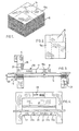
- the printed stock from sheet fed presses comes in the form of a pile of sheets 15 (Fig. 1).
- Each sheet 15a is marked as at 16 to show the cuts required to divide the sheets into pages, coupons, etc. (Fig. 2).
- the apparatus includes a table 17 on which the paper stock is laid up in the pile 15 to a few inches high and a backgauge 18 movable alongside the table by a worm gear 19, and having an upstanding reference marker 18a.
- the gear 19 can be turned manually by a standby wheel 20 or automatically, according to the invention, by a motor mechanism controlled by push buttons in a panel 21 (Fig. 4). Normally, cutters have up to five separate push buttons 22, 22a, 22b, etc. (or a joystick with concealed switches) to provide fast forward, slow forward, reverse, sometimes slow reverse and stop.
- the push buttons or switches are connected to a control box (not shown) through relays and other circuitry which may be of a conventional nature which, in turn, governs the direction and speed of the motor 25 (Fig. 3).
- the cutting procedure is as follows.
- the backgauge 18 is moved to the first cutting position.
- the paper stock pile 15 is laid on the table and pushed firmly against the backgauge 18.
- the driving mechanism is activated and the clamp 26 squeezes the paper stock down.
- the display 29 (Fig. 4) displays the position of the backgauge 18.
- the optical signalling disc assembly S ( Figure 8) is fixedly mounted on the worm shaft 19.
- this assembly is made up of arcuate complementary plates 30 and 31 ( Figure 6), preferably of sheet metal and respectively mounted on hub segments 32 and 33, preferably of fiber.
- Each plate 30, 31, has an arcuate marginal track made up of a regular series of radial slots 35, and, spaced inwards from the track, a single slot 36.
- the hub segment 32 for example, has inner and outer axially extending faces 32a and 32b and adjoining end faces. The inner face 32a ends at a narrow flange 32d.
- the other hub is similar, as shown by like numerals.
- the disc 30 is secured to the hub segment as follows.
- the plate 30 is juxtaposed and adhesively secured to an end face with its inner edge abutting the flange 32d.
- Screws 37 are provided to extend through openings in the segment 32 and into the segment 33 so that the segments 32 and 33 may be drawn together about the shaft 19 and clamped to it.
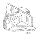
- the optical disc S mounted on shaft 19, is enclosed within a protective casing R, mounted on the frame of the apparatus, which houses the photoelectric cells and light emitting means, which are responsive to the movements of the disc S.
- the casing R is made up of similar companion sheet metal shells R, and R 2 which fit about the shaft 19. In the preferred form shownin Figs. 6 and 7, these shells are of generally circular contour.
- the shell R i for example, is made up of spaced-apart semi-circular sidewalls 50 and extending between them a bridging wall 51 having a connecting flange 51 a extending outward at each end provided with holes connected to the companion flange of the shell R 2 . Extending inward from the straight edge of each wall 50 is an arcuate recess 50b having a diameter sufficiently larger than that of the shaft 19 to leave a small clearance gap when the casing is mounted beside the shaft.
- the shell R 2 is of the same construction as the shell R i .
- Both shells R, and R 2 are provided with dust-stripping.
- a shaped piece of felt 64 (shown in phantom lines in Fig. 6) is mounted on the inside of each wall 50, 50a and projects slightly beyond the margin of the wall and is adapted about the recess 50b to bridge the gap between the shell R and the shaft 19 and the straight edge so as to overlap the fissure between the abutting straight edges of the walls 50 and 50a to bar dust from entering between the shells R, and R 2 .
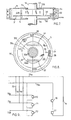
- the circuit board 61 mounts three photocells 70, 71 and 72 ( Figure 9), connected to terminals 70a and 70b, and balancing resistors 73, 74 and 75.
- Circuit board 60 mounts two light emitting diodes 76 and 77 connected between terminals 76a and 77a and intervening current limiting resistor 78.
- each photocell 70, 71 and 72 is connected to one of the terminals 70a, 71 a and 72a leading to the microcomputer which controls the backgauge of the cutter, as described in the specification, and through a resistor 73, 74 and 75 to the positive supply line 78a.
- the encoder assembly is mounted on the apparatus as follows.
- the shell R 1 is brought into position near the shaft 19 and is screwed to the brackets 80 fixed to the machine frame. Then, a segment of the disc S is manipulated into position within the casing R and next to the shaft 19 and the other disc segment is abutted against it about the shaft and the two segments loosely secured together. Then the disc S is rotated to its proper position relative to the photocells and clamped to the shaft 19 by tightening the screws 37.
- An opaque patch is secured to the plate 30 to overlap the gap between the respective plates 30 and 31 at each side of the hub and placed radially so as to overlap the slot 36.
- the patch serves the dual function of screening the gap 38 from the slot 36, and, as sighting means, showing the width of the gap between the respective plates 30 and 31, to aid in adjusting the gaps at each side of the hub.
- the device is now functional and it merely remains for the shell R 2 to be abutted against the shell R 1 and secured to it by screws through the overlapping flanges to complete the protective casing R.
- the casing R isolates the disc S, the photocells, and light emitting device from the surrounding atmosphere. This provides protection from dust which would otherwise accumulate and interfere with the operation of the device.
- the shells are preferably drawn from sheet metal, but could be molded from plastic material.
- the disc segments are desirably made of thin sheet metal punched to provide the sensing slots.
- the disc assembly could be similar to that shown in the applicant's prior application.
- the hub elements may conveniently be made from resin impregnated fiber- board.
- the circuit boards may be made of any convenient insulating material, for example, fiber- board.
Landscapes
- Engineering & Computer Science (AREA)
- Theoretical Computer Science (AREA)
- Optical Transform (AREA)
- Control Of Position Or Direction (AREA)
- Analogue/Digital Conversion (AREA)
- Control Of Electric Motors In General (AREA)
Claims (10)
Priority Applications (1)
| Application Number | Priority Date | Filing Date | Title |
|---|---|---|---|
| AT81304738T ATE25451T1 (de) | 1980-10-15 | 1981-10-12 | Kodierer fuer die maschinensteuerung. |
Applications Claiming Priority (2)
| Application Number | Priority Date | Filing Date | Title |
|---|---|---|---|
| CA362421 | 1980-10-15 | ||
| CA000362421A CA1166713A (en) | 1980-10-15 | 1980-10-15 | Optical disc shaft encoder for machine control |
Publications (3)
| Publication Number | Publication Date |
|---|---|
| EP0050461A2 EP0050461A2 (de) | 1982-04-28 |
| EP0050461A3 EP0050461A3 (en) | 1983-10-05 |
| EP0050461B1 true EP0050461B1 (de) | 1987-02-04 |
Family
ID=4118156
Family Applications (1)
| Application Number | Title | Priority Date | Filing Date |
|---|---|---|---|
| EP81304738A Expired EP0050461B1 (de) | 1980-10-15 | 1981-10-12 | Kodierer für die Maschinensteuerung |
Country Status (5)
| Country | Link |
|---|---|
| EP (1) | EP0050461B1 (de) |
| JP (1) | JPS57127809A (de) |
| AT (1) | ATE25451T1 (de) |
| CA (1) | CA1166713A (de) |
| DE (1) | DE3175917D1 (de) |
Cited By (1)
| Publication number | Priority date | Publication date | Assignee | Title |
|---|---|---|---|---|
| RU2210127C2 (ru) * | 2001-04-17 | 2003-08-10 | Казаков Энвер Акрамович | Контроллер для управления транспортным средством |
Families Citing this family (3)
| Publication number | Priority date | Publication date | Assignee | Title |
|---|---|---|---|---|
| JPH0544731Y2 (de) * | 1987-01-20 | 1993-11-15 | ||
| US8947076B2 (en) | 2010-01-18 | 2015-02-03 | Bourns, Inc. | High resolution non-contacting multi-turn position sensor |
| CN107314781B (zh) * | 2017-07-11 | 2020-08-21 | 南阳凯鑫光电股份有限公司 | 光电编码器旋转保护装置及光电编码器码盘 |
Family Cites Families (3)
| Publication number | Priority date | Publication date | Assignee | Title |
|---|---|---|---|---|
| US1500579A (en) * | 1923-08-06 | 1924-07-08 | William G Eager | Tachometer drive |
| DE821561C (de) * | 1950-06-18 | 1951-11-19 | Vdo Tachometer A G | Gehaese fuer Messgeraete, insbesondere fuer Fahrzeug-Tachometer |
| US3693024A (en) * | 1971-05-17 | 1972-09-19 | Litton Systems Inc | Rotational shaft encoder having a bearing tube having a slot therein |
-
1980
- 1980-10-15 CA CA000362421A patent/CA1166713A/en not_active Expired
-
1981
- 1981-10-12 EP EP81304738A patent/EP0050461B1/de not_active Expired
- 1981-10-12 AT AT81304738T patent/ATE25451T1/de not_active IP Right Cessation
- 1981-10-12 DE DE8181304738T patent/DE3175917D1/de not_active Expired
- 1981-10-15 JP JP56165583A patent/JPS57127809A/ja active Pending
Cited By (1)
| Publication number | Priority date | Publication date | Assignee | Title |
|---|---|---|---|---|
| RU2210127C2 (ru) * | 2001-04-17 | 2003-08-10 | Казаков Энвер Акрамович | Контроллер для управления транспортным средством |
Also Published As
| Publication number | Publication date |
|---|---|
| JPS57127809A (en) | 1982-08-09 |
| EP0050461A2 (de) | 1982-04-28 |
| CA1166713A (en) | 1984-05-01 |
| DE3175917D1 (en) | 1987-03-12 |
| EP0050461A3 (en) | 1983-10-05 |
| ATE25451T1 (de) | 1987-02-15 |
Similar Documents
| Publication | Publication Date | Title |
|---|---|---|
| US4365152A (en) | Encoder for machine control | |
| AU534437B2 (en) | Control circuit for the drive current of a laser | |
| AU6346286A (en) | A cartridge for a gaming machine | |
| AU5200486A (en) | Guard for rotary cutting machine | |
| DE3063491D1 (en) | Device for mounting a circular saw blade on a driving shaft | |
| AU576148B2 (en) | Foil arrangement for a planing craft | |
| AU545406B2 (en) | Severing blade for use with a box containing sheet web | |
| AU5756686A (en) | A radial tire for heavy duty | |
| GB2021812A (en) | Electronic control unit for a supplementary drive system on a vehicle | |
| AU3303384A (en) | A change speed operating apparatus for a tractor | |
| AU583302B2 (en) | A hub for a concrete saw blade | |
| EP0050461B1 (de) | Kodierer für die Maschinensteuerung | |
| AU525083B2 (en) | Monitoring system for monitoring a field | |
| AU3895189A (en) | Rotary cutter for cutting a continuous corrugated strip | |
| DE3174534D1 (en) | Control system for operating the paper carriage in a printer system having microprocessor control | |
| AU3266889A (en) | Cutting blade for a mowing apparatus | |
| AU6170680A (en) | Line adjustment for a typewriter | |
| AU532677B2 (en) | Cutting unit for a shaving apparatus | |
| AU520564B2 (en) | Dust guard for a locomotive axle bearing | |
| AU587139B2 (en) | Improved cutter wheel for a dredge | |
| AU502881B2 (en) | Dilutable resole resin solutions having stabilized dispersed inert salts | |
| AU520301B2 (en) | Control system for a reciprocating carriage drive system | |
| EP0060304A4 (de) | Industrielle robotereinheit mit stromkontrollfunktion eines antriebsmotors. | |
| AU553516B2 (en) | Rotor for a hysteresis motor | |
| AU7748181A (en) | Control device for a direct current motor |
Legal Events
| Date | Code | Title | Description |
|---|---|---|---|
| PUAI | Public reference made under article 153(3) epc to a published international application that has entered the european phase |
Free format text: ORIGINAL CODE: 0009012 |
|
| AK | Designated contracting states |
Designated state(s): AT CH DE FR GB IT LI NL SE |
|
| PUAL | Search report despatched |
Free format text: ORIGINAL CODE: 0009013 |
|
| AK | Designated contracting states |
Designated state(s): AT CH DE FR GB IT LI NL SE |
|
| 17P | Request for examination filed |
Effective date: 19831219 |
|
| R17P | Request for examination filed (corrected) |
Effective date: 19831220 |
|
| GRAA | (expected) grant |
Free format text: ORIGINAL CODE: 0009210 |
|
| AK | Designated contracting states |
Kind code of ref document: B1 Designated state(s): AT CH DE FR GB IT LI NL SE |
|
| PG25 | Lapsed in a contracting state [announced via postgrant information from national office to epo] |
Ref country code: NL Effective date: 19870204 Ref country code: LI Effective date: 19870204 Ref country code: IT Free format text: LAPSE BECAUSE OF FAILURE TO SUBMIT A TRANSLATION OF THE DESCRIPTION OR TO PAY THE FEE WITHIN THE PRESCRIBED TIME-LIMIT;WARNING: LAPSES OF ITALIAN PATENTS WITH EFFECTIVE DATE BEFORE 2007 MAY HAVE OCCURRED AT ANY TIME BEFORE 2007. THE CORRECT EFFECTIVE DATE MAY BE DIFFERENT FROM THE ONE RECORDED. Effective date: 19870204 Ref country code: FR Free format text: THE PATENT HAS BEEN ANNULLED BY A DECISION OF A NATIONAL AUTHORITY Effective date: 19870204 Ref country code: CH Effective date: 19870204 Ref country code: AT Effective date: 19870204 |
|
| REF | Corresponds to: |
Ref document number: 25451 Country of ref document: AT Date of ref document: 19870215 Kind code of ref document: T |
|
| PG25 | Lapsed in a contracting state [announced via postgrant information from national office to epo] |
Ref country code: SE Effective date: 19870228 |
|
| REF | Corresponds to: |
Ref document number: 3175917 Country of ref document: DE Date of ref document: 19870312 |
|
| REG | Reference to a national code |
Ref country code: CH Ref legal event code: PL |
|
| EN | Fr: translation not filed | ||
| NLV1 | Nl: lapsed or annulled due to failure to fulfill the requirements of art. 29p and 29m of the patents act | ||
| PLBE | No opposition filed within time limit |
Free format text: ORIGINAL CODE: 0009261 |
|
| STAA | Information on the status of an ep patent application or granted ep patent |
Free format text: STATUS: NO OPPOSITION FILED WITHIN TIME LIMIT |
|
| 26N | No opposition filed | ||
| PGFP | Annual fee paid to national office [announced via postgrant information from national office to epo] |
Ref country code: DE Payment date: 19881227 Year of fee payment: 8 |
|
| PG25 | Lapsed in a contracting state [announced via postgrant information from national office to epo] |
Ref country code: GB Effective date: 19891012 |
|
| GBPC | Gb: european patent ceased through non-payment of renewal fee | ||
| PG25 | Lapsed in a contracting state [announced via postgrant information from national office to epo] |
Ref country code: DE Effective date: 19900703 |