EP0050291A2 - Support for hoses - Google Patents
Support for hoses Download PDFInfo
- Publication number
- EP0050291A2 EP0050291A2 EP81108219A EP81108219A EP0050291A2 EP 0050291 A2 EP0050291 A2 EP 0050291A2 EP 81108219 A EP81108219 A EP 81108219A EP 81108219 A EP81108219 A EP 81108219A EP 0050291 A2 EP0050291 A2 EP 0050291A2
- Authority
- EP
- European Patent Office
- Prior art keywords
- hose
- housing parts
- recess
- holder according
- hose holder
- Prior art date
- Legal status (The legal status is an assumption and is not a legal conclusion. Google has not performed a legal analysis and makes no representation as to the accuracy of the status listed.)
- Granted
Links
Images
Classifications
-
- F—MECHANICAL ENGINEERING; LIGHTING; HEATING; WEAPONS; BLASTING
- F16—ENGINEERING ELEMENTS AND UNITS; GENERAL MEASURES FOR PRODUCING AND MAINTAINING EFFECTIVE FUNCTIONING OF MACHINES OR INSTALLATIONS; THERMAL INSULATION IN GENERAL
- F16L—PIPES; JOINTS OR FITTINGS FOR PIPES; SUPPORTS FOR PIPES, CABLES OR PROTECTIVE TUBING; MEANS FOR THERMAL INSULATION IN GENERAL
- F16L3/00—Supports for pipes, cables or protective tubing, e.g. hangers, holders, clamps, cleats, clips, brackets
-
- Y—GENERAL TAGGING OF NEW TECHNOLOGICAL DEVELOPMENTS; GENERAL TAGGING OF CROSS-SECTIONAL TECHNOLOGIES SPANNING OVER SEVERAL SECTIONS OF THE IPC; TECHNICAL SUBJECTS COVERED BY FORMER USPC CROSS-REFERENCE ART COLLECTIONS [XRACs] AND DIGESTS
- Y10—TECHNICAL SUBJECTS COVERED BY FORMER USPC
- Y10T—TECHNICAL SUBJECTS COVERED BY FORMER US CLASSIFICATION
- Y10T24/00—Buckles, buttons, clasps, etc.
- Y10T24/34—Combined diverse multipart fasteners
- Y10T24/3427—Clasp
-
- Y—GENERAL TAGGING OF NEW TECHNOLOGICAL DEVELOPMENTS; GENERAL TAGGING OF CROSS-SECTIONAL TECHNOLOGIES SPANNING OVER SEVERAL SECTIONS OF THE IPC; TECHNICAL SUBJECTS COVERED BY FORMER USPC CROSS-REFERENCE ART COLLECTIONS [XRACs] AND DIGESTS
- Y10—TECHNICAL SUBJECTS COVERED BY FORMER USPC
- Y10T—TECHNICAL SUBJECTS COVERED BY FORMER US CLASSIFICATION
- Y10T24/00—Buckles, buttons, clasps, etc.
- Y10T24/44—Clasp, clip, support-clamp, or required component thereof
- Y10T24/44966—Clasp, clip, support-clamp, or required component thereof having gripping member shifted by operator
- Y10T24/44974—Threaded cylindrical rod and mating cavity
Definitions
- the invention relates to a hose holder, in particular for hydraulic hoses, consisting of a first and a second housing part, each of which has at least one recess which is semicircular in cross section and is connected to one another by connecting means such that the two semicircular recesses together form a recess with a circular cross section which has an open end.
- the invention has for its object to improve the hose holder explained in the introduction so that the uncoupled end of a hydraulic hose can be fixed in a simple and safe manner, the hose end being protected against contamination at the same time.
- the holder can be a spring that simply and securely locks the hose end inserted into the aforementioned recess.
- the recess is only open to one side of the housing; this insertion opening is largely closed by the inserted hose end, so that the hose end is protected from contamination.
- a clamp holder connected to the first and second housing part can be provided which holds a hose section located at a distance from the end of the hose.
- each circular opening of the housing parts is covered by a dust cap which has a plurality of bendable circular segments which allow the interrupter plug-in coupling to be pushed through.
- the hose holder according to the invention is inexpensive to manufacture and can be easily attached to the frame of a vehicle or a working device.
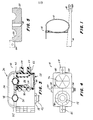
- FIG. 1 shows a hose holder 10 for securely fixing a disconnected hydraulic hose 12.
- the hose holder 10 can be mounted on a frame 14 of a vehicle or of an implement.
- the arm 14 has a coupling 16, as is common in agricultural implements.
- an interrupter plug-in coupling 18 connected to the end of a hydraulic hose 12 is inserted into the hose holder 10.
- the hose holder 10 shown can fix a section of the hydraulic hose 12 that is at a greater distance from the coupling 18 mentioned.
- the hose holder 10 consists of a first and a second housing part 20, 22, connecting means 23 and a holder 24.
- the two housing parts 20, 22 each have at least one recess 25 which is semicircular in cross section (see FIG. 5 ), which together form a circular recess 26 with only one open end 28 when the two housing parts 20, 22 are connected to one another via the connecting means 23.
- the coupling 18 is inserted into the open end 28 of the said recess 26.
- the connecting means 23 consist of bolts 30 which are each inserted through a bore 32 and secured with a retaining nut 34. Other connection means such as Pins, screws or clips can also be used.
- the holder 24 is arranged between the first and second housing parts 20, 22 and projects into the recess 26 in such a way that it can act on the outer circumferential surface of the inserted plug-in coupling 18 and can thus lock it within the recess 26.
- the Hal ter 24 is preferably arranged on the inner circumferential surface of the recess 26 and can be a flexible, stretchable ring, a spring-loaded device, or a spring itself, such as an annular spring; other releasable locking means are conceivable.
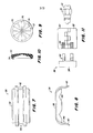
- FIGS. 7 and 8 show a clamping bracket 36 which, according to FIG. 3, can be pressed onto the two housing parts 20, 22.
- the clamping bracket 36 is used to clamp a section of the hydraulic hose 12 to the housing parts 20, 22 and consists of a one-piece clamping part 38 with flexible tongues 40, 42 lying opposite and aligned with one another.
- One or more tongues can be arranged on each side of the clamping part 38, each of which is provided with teeth 44 which can be designed like a saw, the cutting edges being directed towards the clamping part 38.
- These teeth 44 are pressed into teeth 46 which are provided on the side walls of the two housing parts 20, 22.
- the clamping part 38 also has one or more depressions 48 which run at right angles to the tongues 40, 42.
- Figure 2 shows a modified embodiment for the clamp bracket 36.
- a one-piece clamping part 52 has opposing and aligned flexible fingers 54, 56, which are hook-shaped and engage under shoulders 58, 60 of the two housing parts 20, 22.
- a depression 62 is provided between the said fingers, which depression is assigned to a depression 50 provided in the two housing parts 20, 22.
- the depressions 48, 62 and 50 serve to clamp a hose section which is at a greater distance from the plug coupling 18.
- the clamp bracket 36 for which other embodiments are also conceivable, can thus prevent a longer section of the hydraulic hose 12 hangs freely and can twist.
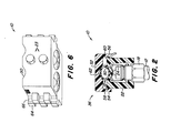
- FIGS. 5 and 6 in particular show that the two housing parts 20, 22 have on one side a plurality of upper and lower lugs 64 which are arranged offset with respect to one another and which lie on both sides of the hose holder 10 when the housing parts 20, 22 are connected to one another, since the two housing parts 20, 22 are formed symmetrically.
- Each lug 64 has a bore 66 which is semicircular in cross section, the axis of which runs through all staggered lugs on one side of the housing.
- a second, identically designed tube holder can be connected to the tube holder 10, in which only a pin (not shown) is inserted through the mutually aligned bores 66 of the lugs 64.
- Each hose holder 10 can be designed so that it can hold two hydraulic hoses 12, since most hydraulic devices are equipped with two hoses. In large agricultural tractors, four, six or even eight hydraulic hoses are connected so that several hose holders 10 can be connected here.
- FIGS. 9 and 10 show a flexible dust cap 70 which is already the subject of the older European patent application No. 81103698.7.
- the dust cap 70 is divided by a plurality of radial slots 74 into sealing lips 72 in the form of segments of a circle, which can have a supporting rib 76 on one side for reinforcement.
- This dust cap 70 is used to cover the opening 28 of the recess 26. If a plug-in coupling 18 is inserted through this dust cap 70 into the recess 26, the sealing lips 72 are bent inwards and lie sealingly against the outer lateral surface of the plug-in coupling 18.
- the dust cap 70 preferably consists of a flexible, rubber-like material and can have a metal insert 78, which serves to stabilize the shape of the dust cap 70 and to secure the fit of the dust cap within the opening 28.
- FIG. 11 shows the plug-in coupling 18, the two housing parts 20, 22 connected to one another and the clamp holder 36. The latter is pressed onto that side of the housing parts 20, 22 which is opposite the opening 28 of the recess 26.
Abstract
Description
Die Erfindung betrifft einen Schlauchhalter, insbesondere für Hydraulikschläuche, bestehend aus einem ersten und einem zweiten Gehäuseteil, die jeweils zumindest eine im Querschnitt halbkreisförmige Ausnehmung aufweisen und durch Verbindungsmittel so miteinander verbunden sind, daß die beiden halbkreisförmigen Ausnehmungen zusammen eine im Querschnitt kreisförmige Ausnehmung bilden, die ein offenes Ende aufweist.The invention relates to a hose holder, in particular for hydraulic hoses, consisting of a first and a second housing part, each of which has at least one recess which is semicircular in cross section and is connected to one another by connecting means such that the two semicircular recesses together form a recess with a circular cross section which has an open end.
Zwischen einem Traktor und einem angehängten Arbeitsgerät sind häufig mehrere Hydraulikschläuche verlegt, die üblicherweise an einem oder beiden Enden eine Unterbrecher-Steckkupplung aufweisen. Soll das Arbeitsgerät vom Traktor abgekuppelt werden, wird die Unterbrecher-Steckkupplung des Hydraulikschlauches abgezogen. Anschließend besteht dann die Gefahr, daß dieses Schlauchende Berührung mit dem Boden bekommt und dadurch verdreckt. Diese Verschmutzung setzt sich an der fettigen Oberfläche der Steckkupplung fest und kann später in den Hydraulikkreislauf gelangen und dort zu Störungen führen. Zur Vermeidung dieser Probleme sind Schlauchhalter entwickelt worden, um den Hydraulikschlauch im Abstand oberhalb des Bodens zu halten. Den meisten der bisherigen Vorschläge haften zwei wesentliche Nachteile an: Es erfordert zu viel Kraft, um die Unterbrecher-Steckkupplung in den Schlauchhalter einzuführen; außerdem ist das Ende der genannten Steckkupplung nicht ausreichend geschützt.Frequently, several hydraulic hoses are laid between a tractor and an attached implement, which usually have an interrupter plug-in coupling at one or both ends. If the implement is to be uncoupled from the tractor, the interrupter plug-in coupling of the hydraulic hose is removed. Then there is the danger that this hose end will come into contact with the ground and thereby get dirty. This contamination settles on the greasy surface of the plug-in coupling and can later get into the hydraulic circuit and cause faults there. To avoid these problems, hose holders have been developed to keep the hydraulic hose at a distance above the ground. Most of the previous proposals have two major disadvantages: too much force is required to insert the interrupter plug-in coupling into the hose holder; except the end of the plug-in coupling mentioned is not adequately protected.
Die US-Patentschriften 3 125 359 und 4 089 087 zeigen zwei Schlauchhalter der in Rede stehenden Art.U.S. Patents 3,125,359 and 4,089,087 show two tube holders of the type in question.
Der Erfindung liegt die Aufgabe zugrunde, den eingangs erläuterten Schlauchhalter so zu verbessern, daß sich das abgekuppelte Ende eines Hydraulikschlauches in einfacher und sicherer Weise festlegen läßt, wobei das Schlauchende gleichzeitig vor Verschmutzung geschützt ist.The invention has for its object to improve the hose holder explained in the introduction so that the uncoupled end of a hydraulic hose can be fixed in a simple and safe manner, the hose end being protected against contamination at the same time.
Diese Aufgabe wird gemäß der Erfindung dadurch gelöst, daß zwischen dem ersten und zweiten Gehäuseteil ein in die kreisförmige Ausnehmung ragender Halter für die Festlegung eines Endes des Schlauches vorgesehen ist.This object is achieved according to the invention in that between the first and second housing parts a protruding into the circular recess holder is provided for fixing one end of the hose.
Dabei kann der Halter eine Feder sein, die das in die genannte Ausnehmung eingesteckte Schlauchende einfach und sicher arretiert. Die Ausnehmung ist erfindungsgemäß nur zu einer Gehäuseseite hin offen; diese Einstecköffnung wird von dem eingesteckten Schlauchende weitgehend verschlossen, so daß das Schlauchende vor Verschmutzung geschützt ist.The holder can be a spring that simply and securely locks the hose end inserted into the aforementioned recess. According to the invention, the recess is only open to one side of the housing; this insertion opening is largely closed by the inserted hose end, so that the hose end is protected from contamination.
Um nicht nur das Schlauchende festzuhalten, kann erfindungsgemäß eine mit dem ersten und zweiten Gehäuseteil verbundene Klemmhalterung vorgesehen werden, die einen im Abstand vom Schlauchende befindlichen Schlauchabschnitt festhält.In order not only to hold the end of the hose, according to the invention a clamp holder connected to the first and second housing part can be provided which holds a hose section located at a distance from the end of the hose.
Zur weiteren Verbesserung des Schutzes gegen Verschmutzung ist es vorteilhaft, wenn das offene Ende jeder kreisförmigen öffnung der Gehäuseteile durch eine Staubkappe abgedeckt ist, die mehrere biegbare Kreissegmente aufweist, die ein Hindurchstecken der Unterbrecher-Steckkupplung ermöglichen.To further improve protection against soiling, it is advantageous if the open end of each circular opening of the housing parts is covered by a dust cap which has a plurality of bendable circular segments which allow the interrupter plug-in coupling to be pushed through.
Der erfindungsgemäße Schlauchhalter ist preiswert in der Herstellung und läßt sich in einfacher Weise auf dem Rahmen eines Fahrzeugs oder eines Arbeitsgerätes befestigen.The hose holder according to the invention is inexpensive to manufacture and can be easily attached to the frame of a vehicle or a working device.
Weitere Merkmale der Erfindung sind Gegenstand der Unteransprüche und werden anhand eines Ausführungsbeispieles hinsichtlich ihrer Vorteile näher erläutert.Further features of the invention are the subject of the subclaims and are explained in more detail with reference to an embodiment with regard to their advantages.
In der Zeichnung sind einige als Ausführungsbeispiele dienende Ausführungsformen der Erfindung dargestellt. Es zeigen:
- Figur 1 in Seitenansicht einen auf einem Träger befestigten Schlauchhalter;
- Figur 2 in vergrößertem Maßstab einen Querschnitt durch den Schlauchhalter mit eingesteckter Unterbrecher-Steckkupplung;
- Figur 3 den Schlauchhalter in Seitenansicht und zum Teil im Längsschnitt;
- Figur 4 die Darstellung gemäß Figur 3 in Stirnansicht;
- Figur 5 einen Längsschnitt durch die untere Hälfte der Darstellung gemäß Figur 4 ;
- Figur 6 den Schlauchhalter in perspektivischer Darstellung;
- Figur 7 ein Klemmteil in Draufsicht;
- Figur 8 die Darstellung gemäß Figur 7 in Seitenansicht;
- Figur 9 eine Staubkappe in Draufsicht;
Figur 10 einen Querschnitt durch die Staubkappe gemäß Figur 9 und- Figur 11 in einer Explosionsdarstellung ein Klemmteil, einen Schlauchhalter sowie eine Unterbrecher-Steckkupplung.
- Figure 1 shows a side view of a hose holder attached to a carrier;
- FIG. 2 shows, on an enlarged scale, a cross section through the hose holder with the interrupter plug-in coupling inserted;
- Figure 3 shows the hose holder in side view and partly in longitudinal section;
- Figure 4 shows the representation of Figure 3 in front view;
- FIG. 5 shows a longitudinal section through the lower half of the illustration according to FIG. 4;
- Figure 6 shows the hose holder in a perspective view;
- Figure 7 is a clamping part in plan view;
- Figure 8 shows the view of Figure 7 in side view;
- Figure 9 is a dust cap in plan view;
- 10 shows a cross section through the dust cap according to Figure 9 and
- FIG. 11 shows an exploded view of a clamping part, a hose holder and an interrupter plug-in coupling.
Figur 1 zeigt einen Schlauchhalter 10 zur sicheren Festlegung eines abgekuppelten Hydraulikschlauches 12. Der Schlauchhalter 10 kann auf einem Rahmen 14 eines Fahrzeugs oder eines Arbeitsgerätes montiert sein. Gemäß Figur 1 weist der Arm 14 eine Kupplung 16 auf, wie sie bei landwirtschaftlichen Arbeitsgeräten üblich ist.FIG. 1 shows a
Gemäß Figur 2 ist in den Schlauchhalter 10 eine mit dem Ende eines Hydraulikschlauches 12 verbundene Unterbrecher-Steckkupplung 18 gesteckt. Außerdem kann der dargestellte Schlauchhalter 10 einen Abschnitt des Hydraulikschlauches 12 festlegen, der in größerem Abstand von der genannten Kupplung 18 liegt.According to FIG. 2, an interrupter plug-in
Gemäß den Figuren 2 bis 6 besteht der Schlauchhalter 10 aus einem ersten und einem zweiten Gehäuseteil 20,22, aus Verbindungsmitteln 23 sowie einem Halter 24. Die beiden Gehäuseteile 20,22 weisen jedes zumindest eine im Querschnitt halbkreisförmig ausgebildete Ausnehmung 25 auf (siehe Figur 5), die zusammen eine im Querschnitt kreisförmige Ausnehmung 26 mit nur einem offenen Ende 28 bilden, wenn die beiden Gehäuseteile 20,22 über die Verbindungsmittel 23 miteinander verbunden sind. Die Kupplung 18 wird in das offene Ende 28 der genannten Ausnehmung 26 gesteckt. Die Verbindungsmittel 23 bestehen bei dem dargestellten Ausführungsbeispiel aus Bolzen 30, die durch jeweils eine Bohrung 32 gesteckt und mit einer Haltemutter 34 gesichert sind. Andere Verbindungsmittel wie z.B. Stifte, Schrauben oder Klipse können ebenfalls verwendet werden.According to FIGS. 2 to 6, the
Der Halter 24 ist zwischen dem ersten und zweiten Gehäuseteil 20, 22 angeordnet und ragt so in die Ausnehmung 26, daß er die äußere Mantelfläche der eingeführten Steckkupplung 18 beaufschlagen und diese somit innerhalb der Ausnehmung 26 arretieren kann. Der Halter 24 ist vorzugsweise an der inneren Mantelfläche der Ausnehmung 26 angeordnet und kann durch einen flexiblen, dehnbaren Ring, eine federbeaufschlagte Einrichtung, oder aber eine Feder selbst sein, wie z.B. eine Ringbandfeder; andere lösbare Arretiermittel sind denkbar.The
Die Figuren 7 und 8 zeigen eine Klemmhalterung 36, die gemäß Figur 3 auf die beiden Gehäuseteile 20,22 aufgedrückt werden kann. Die Klemmhalterung 36 dient zur klemmenden Festlegung eines Abschnitts des Hydraulikschlauches 12 an den Gehäuseteilen 20,22 und besteht aus einem einteiligen Klemmteil 38 mit sich gegenüberliegenden und miteinander fluchtenden flexiblen Zungen 40,42. Auf jeder Seite des Klemmteils 38 können eine oder mehrere Zungen angeordnet sein, die jeweils mit Zähnen 44 versehen sind, die sägeartig ausgebildet sein können, wobei die Schneiden zum Klemmteil 38 hin gerichtet sind. Diese Zähne 44 sind eingedrückt in Zähne 46, die auf den Seitenwandungen der beiden Gehäuseteile 20, 22 vorgesehen sind. Das Klemmteil 38 weist außerdem eine oder mehrere Vertiefungen 48 auf, die rechtwinklig zu den Zungen 40,42 verlaufen.FIGS. 7 and 8 show a
Figur 2 zeigt für die Klemmhalterung 36 eine abgewandelte Ausführungsform. Hier weist ein einteiliges Klemmteil 52 sich gegenüberliegende und miteinander fluchtende flexible Finger 54,56 auf, die hakenförmig ausgebildet sind und Schultern 58,60 der beiden Gehäuseteile 20,22 untergreifen. Zwischen den genannten Fingern ist eine Vertiefung 62 vorgesehen, die einer in den beiden Gehäuseteilen 20,22 vorgesehenen Vertiefung 50 zugeordnet ist. Gemeinsam dienen die Vertiefungen 48,62 und 50 zum Festklemmen eines Schlauchabschnittes, der in größerer Entfernung von der Steckkupplung 18 liegt. Durch die Klemmhalterung 36, für die auch andere Ausführungsformen denkbar sind, läßt sich somit verhindern, daß ein längerer Abschnitt des Hydraulikschlauches 12 frei herumhängt und verdrehen kann.Figure 2 shows a modified embodiment for the
Insbesondere die Figuren 5 und 6 lassen erkennen, daß die beiden Gehäuseteile 20,22 auf einer Seite mehrere gegeneinander versetzt angeordnete obere und untere Nasen 64 aufweisen, die bei der Verbindung der Gehäuseteile 20,22 miteinander auf beiden Seiten des Schlauchhalters 10 liegen, da die beiden Gehäuseteile 20, 22 symmetrisch ausgebildet sind. Jede Nase 64 weist eine im Querschnitt halbkreisförmige Bohrung 66 auf, deren Achse durch alle versetzt angeordneten Nasen auf einer Seite des Gehäuses hindurchläuft. Dadurch läßt sich mit dem Schlauchhalter 10 ein zweiter, identisch ausgebildeter Schlauchhalter verbinden, in dem lediglich ein nicht dargestellter Stift durch die miteinander fluchtenden Bohrungen 66 der Nasen 64 gesteckt wird.FIGS. 5 and 6 in particular show that the two
Jeder Schlauchhalter 10 kann so ausgebildet sein, daß er zwei Hydraulikschläuche 12 festhalten kann, da die meisten Hydraulikeinrichtungen mit zwei Schläuchen ausgestattet sind. Bei großen landwirtschaftlichen Traktoren sind vier, sechs oder sogar acht Hydraulikschläuche angeschlossen, so daß hier mehrere Schlauchhalter 10 miteinander verbunden werden können.Each
Die Figuren 9 und 10 zeigen eine biegsame Staubkappe 70,die bereits Gegenstand der älteren europäischen Patentanmeldung Nr. 81103698.7 ist. Die Staubkappe 70 ist durch mehrere Radialschlitze 74 in kreissegmentförmige Dichtlippen 72 unterteilt, die zur Versteifung auf ihrer einen Seite eine Stützrippe 76 aufweisen können. Diese Staubkappe 70 dient zur Abdeckung der öffnung 28 der Ausnehmung 26. Wird eine Steckkupplung 18 durch diese Staubkappe 70 hindurch in die Ausnehmung 26 eingeführt, werden die Dichtlippen 72 nach innen gebogen und legen sich dabei abdichtend an der äußeren Mantelfläche der Steckkupplung 18 an. Die Staubkappe 70 besteht vorzugsweise aus einem flexiblen, gummiähnlichen Material und kann eine Metalleinlage 78 aufweisen, die zur Formstabilisierung der Staubkappe 70 sowie zur Sicherung des Sitzes der Staubkappe innerhalb der öffnung 28 dient.FIGS. 9 and 10 show a
Die Explosionsdarstellung gemäß Figur 11 zeigt die Steckkupplung 18, die beiden miteinander verbundenen Gehäuseteile 20,22 sowie die Klemmhalterung 36. Letztere wird auf diejenige Seite der Gehäuseteile 20,22 gedrückt, die der öffnung 28 der Ausnehmung 26 gegenüberliegt.The exploded view according to FIG. 11 shows the plug-in
Vorstehenden Erläuterungen entnimmt ein Durchschnittsfachmann zahlreiche Möglichkeiten zur Modifikation und sonstigen Abwandlung, die jedoch alle durch die Erfindung mit erfaßt sein sollen.From the above explanations, an average person skilled in the art takes numerous possibilities for modification and other modification, which, however, should all be covered by the invention.
Claims (13)
Priority Applications (1)
| Application Number | Priority Date | Filing Date | Title |
|---|---|---|---|
| AT81108219T ATE27993T1 (en) | 1980-10-20 | 1981-10-12 | HOSE HOLDER. |
Applications Claiming Priority (2)
| Application Number | Priority Date | Filing Date | Title |
|---|---|---|---|
| US198371 | 1980-10-20 | ||
| US06/198,371 US4395800A (en) | 1980-10-20 | 1980-10-20 | Hose retainer |
Publications (3)
| Publication Number | Publication Date |
|---|---|
| EP0050291A2 true EP0050291A2 (en) | 1982-04-28 |
| EP0050291A3 EP0050291A3 (en) | 1985-03-27 |
| EP0050291B1 EP0050291B1 (en) | 1987-06-24 |
Family
ID=22733120
Family Applications (1)
| Application Number | Title | Priority Date | Filing Date |
|---|---|---|---|
| EP81108219A Expired EP0050291B1 (en) | 1980-10-20 | 1981-10-12 | Support for hoses |
Country Status (10)
| Country | Link |
|---|---|
| US (1) | US4395800A (en) |
| EP (1) | EP0050291B1 (en) |
| JP (1) | JPS5797983A (en) |
| AT (1) | ATE27993T1 (en) |
| AU (1) | AU543648B2 (en) |
| BR (1) | BR8106725A (en) |
| CA (1) | CA1173013A (en) |
| DE (1) | DE3176281D1 (en) |
| ES (1) | ES269208Y (en) |
| ZA (1) | ZA816604B (en) |
Cited By (1)
| Publication number | Priority date | Publication date | Assignee | Title |
|---|---|---|---|---|
| US10677384B2 (en) | 2016-12-22 | 2020-06-09 | Stucchi USA, Inc. | Push pull double swivel coupler |
Families Citing this family (8)
| Publication number | Priority date | Publication date | Assignee | Title |
|---|---|---|---|---|
| US4483371A (en) * | 1983-07-22 | 1984-11-20 | Susin Victor G | Protective holder for hose tip assembly |
| US4902043A (en) * | 1985-09-17 | 1990-02-20 | John T. Hoskins | Fluid coupling and seal assembly |
| US4714279A (en) * | 1986-11-03 | 1987-12-22 | Lincoln Custeau | Exhaust pipe coupler |
| US4875709A (en) * | 1988-02-26 | 1989-10-24 | Caroll James E | Controlled leak path |
| US5082217A (en) * | 1991-03-27 | 1992-01-21 | Deere & Company | Hydraulic hose support for an implement |
| US7658756B2 (en) * | 2006-04-12 | 2010-02-09 | Smiths Medical Asd, Inc. | Hose retainer for thermal blanket |
| SE530620C2 (en) * | 2006-12-01 | 2008-07-22 | Nordhydraulic Ab | Parking means for hydraulic coupling |
| WO2019232056A1 (en) * | 2018-05-29 | 2019-12-05 | Gentherm Medical, Llc | Integral inlet port assembly |
Citations (8)
| Publication number | Priority date | Publication date | Assignee | Title |
|---|---|---|---|---|
| US1384332A (en) * | 1920-09-25 | 1921-07-12 | Brisco J Mullenux | Hose-coupling |
| US2414220A (en) * | 1943-05-13 | 1947-01-14 | Milwaukee Gas Specialty Co | Temperature control and safety shutoff |
| DE1727460U (en) * | 1956-04-25 | 1956-08-02 | Lutz Maschb K G | PROTECTIVE AND MOUNTING DEVICE FOR TRAILER LIGHT PLUG. |
| US3125359A (en) * | 1964-03-17 | Push-pull breakaway coupling | ||
| US3245428A (en) * | 1963-11-08 | 1966-04-12 | Berg Mfg & Sales Co | Flexible seal for use in a gladhand assembly |
| US3279014A (en) * | 1963-10-29 | 1966-10-18 | Fischer Artur | Cable clamp |
| US3412760A (en) * | 1966-01-10 | 1968-11-26 | Imp Eastman Corp | Hose assembly |
| US4089087A (en) * | 1977-03-25 | 1978-05-16 | Leroy Marvin Heitman | Clamp for hydraulic hoses |
Family Cites Families (10)
| Publication number | Priority date | Publication date | Assignee | Title |
|---|---|---|---|---|
| US458188A (en) * | 1891-08-25 | Electric clamp | ||
| US1333616A (en) * | 1919-12-23 | 1920-03-16 | Chris S Hall | Soldering-iron holder |
| US2683468A (en) * | 1948-03-04 | 1954-07-13 | Chicago Metal Hose Corp | Hose support |
| US2937835A (en) * | 1957-05-02 | 1960-05-24 | Csmereka John | Universal cable clamp |
| US3760811A (en) * | 1970-01-20 | 1973-09-25 | D Andrew | Endotracheal tube clamp |
| US3650545A (en) * | 1970-03-09 | 1972-03-21 | William E Freed | Hose support and guide |
| US3757031A (en) * | 1972-05-02 | 1973-09-04 | Thomas & Betts Corp | The like selectively closable protective enclosure for electrical splices and |
| AT346135B (en) * | 1975-11-11 | 1978-10-25 | Siemens Ag Oesterreich | DEVICE FOR MECHANICAL CONNECTION OF TWO PLASTIC PARTS |
| US4311992A (en) * | 1979-07-02 | 1982-01-19 | Eaton Corporation | Reusable releasable fastener |
| US4329857A (en) * | 1980-05-16 | 1982-05-18 | Deere & Company | Coupler cover |
-
1980
- 1980-10-20 US US06/198,371 patent/US4395800A/en not_active Expired - Lifetime
-
1981
- 1981-09-10 AU AU75118/81A patent/AU543648B2/en not_active Ceased
- 1981-09-23 ZA ZA816604A patent/ZA816604B/en unknown
- 1981-10-08 CA CA000387550A patent/CA1173013A/en not_active Expired
- 1981-10-12 EP EP81108219A patent/EP0050291B1/en not_active Expired
- 1981-10-12 AT AT81108219T patent/ATE27993T1/en active
- 1981-10-12 DE DE8181108219T patent/DE3176281D1/en not_active Expired
- 1981-10-15 JP JP56164907A patent/JPS5797983A/en active Pending
- 1981-10-19 BR BR8106725A patent/BR8106725A/en unknown
- 1981-10-19 ES ES1981269208U patent/ES269208Y/en not_active Expired
Patent Citations (8)
| Publication number | Priority date | Publication date | Assignee | Title |
|---|---|---|---|---|
| US3125359A (en) * | 1964-03-17 | Push-pull breakaway coupling | ||
| US1384332A (en) * | 1920-09-25 | 1921-07-12 | Brisco J Mullenux | Hose-coupling |
| US2414220A (en) * | 1943-05-13 | 1947-01-14 | Milwaukee Gas Specialty Co | Temperature control and safety shutoff |
| DE1727460U (en) * | 1956-04-25 | 1956-08-02 | Lutz Maschb K G | PROTECTIVE AND MOUNTING DEVICE FOR TRAILER LIGHT PLUG. |
| US3279014A (en) * | 1963-10-29 | 1966-10-18 | Fischer Artur | Cable clamp |
| US3245428A (en) * | 1963-11-08 | 1966-04-12 | Berg Mfg & Sales Co | Flexible seal for use in a gladhand assembly |
| US3412760A (en) * | 1966-01-10 | 1968-11-26 | Imp Eastman Corp | Hose assembly |
| US4089087A (en) * | 1977-03-25 | 1978-05-16 | Leroy Marvin Heitman | Clamp for hydraulic hoses |
Cited By (1)
| Publication number | Priority date | Publication date | Assignee | Title |
|---|---|---|---|---|
| US10677384B2 (en) | 2016-12-22 | 2020-06-09 | Stucchi USA, Inc. | Push pull double swivel coupler |
Also Published As
| Publication number | Publication date |
|---|---|
| BR8106725A (en) | 1982-07-06 |
| AU543648B2 (en) | 1985-04-26 |
| AU7511881A (en) | 1982-04-29 |
| ES269208U (en) | 1983-06-16 |
| ES269208Y (en) | 1984-01-16 |
| JPS5797983A (en) | 1982-06-17 |
| EP0050291B1 (en) | 1987-06-24 |
| DE3176281D1 (en) | 1987-07-30 |
| ATE27993T1 (en) | 1987-07-15 |
| ZA816604B (en) | 1983-04-27 |
| US4395800A (en) | 1983-08-02 |
| CA1173013A (en) | 1984-08-21 |
| EP0050291A3 (en) | 1985-03-27 |
Similar Documents
| Publication | Publication Date | Title |
|---|---|---|
| DE69816935T2 (en) | Sleeve for a pipe element | |
| DE2503606C3 (en) | Pipe connector | |
| EP0040403B1 (en) | Protection cap to prevent the dirtying of the front surface of a coupling half | |
| DE1957699A1 (en) | Connection clamp for pipes and hose connectors pushed into one another | |
| DD146661A5 (en) | CONNECTORS FOR OPTICAL FIBERS | |
| DE2143574A1 (en) | ||
| DE3426089A1 (en) | DUST CAP FOR LIQUID COUPLING | |
| EP0050291B1 (en) | Support for hoses | |
| DE69732815T2 (en) | Multi-fiber connector | |
| EP1137893A1 (en) | Coupling system with blocking device | |
| DE3529052C2 (en) | Hose connector | |
| AT392443B (en) | TIRE AND SLIP PROTECTION NET FOR VEHICLE TIRES | |
| DE69730403T2 (en) | A method and apparatus for improving the retention of a snap fit accessory on a cable tray base | |
| EP1801485B1 (en) | Coupling device for interconnecting multiple fluid lines | |
| DE19504821C2 (en) | Device for determining an electrical or electronic component with a housing | |
| DE102018132279A1 (en) | PIPE CLAMP ARRANGEMENT | |
| DE102010013159A1 (en) | connector | |
| DE19715967A1 (en) | Connector for coupling a pipe with a small diameter | |
| DE19502681A1 (en) | Strain relief and fastener | |
| DE2046922A1 (en) | Lamp base | |
| DE3144547A1 (en) | Adjustable mirror for motor vehicles | |
| DE2834432A1 (en) | QUICK FASTENING | |
| DE3223864A1 (en) | PROTECTIVE DEVICE FOR THE EXTERNAL JOINT FORK OF A CARDAN SHAFT, ESPECIALLY FOR AGRICULTURAL MACHINERY | |
| EP1380784B1 (en) | Holding clamp | |
| EP0992728B1 (en) | Holder for elongate articles such as pipes or hoses |
Legal Events
| Date | Code | Title | Description |
|---|---|---|---|
| PUAI | Public reference made under article 153(3) epc to a published international application that has entered the european phase |
Free format text: ORIGINAL CODE: 0009012 |
|
| AK | Designated contracting states |
Designated state(s): AT DE FR GB IT NL SE |
|
| ITCL | It: translation for ep claims filed |
Representative=s name: LENZI & C. |
|
| TCNL | Nl: translation of patent claims filed | ||
| PUAL | Search report despatched |
Free format text: ORIGINAL CODE: 0009013 |
|
| AK | Designated contracting states |
Designated state(s): AT DE FR GB IT NL SE |
|
| 17P | Request for examination filed |
Effective date: 19850301 |
|
| 17Q | First examination report despatched |
Effective date: 19860516 |
|
| ITF | It: translation for a ep patent filed |
Owner name: LENZI & C. |
|
| GRAA | (expected) grant |
Free format text: ORIGINAL CODE: 0009210 |
|
| AK | Designated contracting states |
Kind code of ref document: B1 Designated state(s): AT DE FR GB IT NL SE |
|
| REF | Corresponds to: |
Ref document number: 27993 Country of ref document: AT Date of ref document: 19870715 Kind code of ref document: T |
|
| REF | Corresponds to: |
Ref document number: 3176281 Country of ref document: DE Date of ref document: 19870730 |
|
| ET | Fr: translation filed | ||
| PG25 | Lapsed in a contracting state [announced via postgrant information from national office to epo] |
Ref country code: AT Effective date: 19871012 |
|
| PG25 | Lapsed in a contracting state [announced via postgrant information from national office to epo] |
Ref country code: SE Effective date: 19871013 |
|
| PLBE | No opposition filed within time limit |
Free format text: ORIGINAL CODE: 0009261 |
|
| STAA | Information on the status of an ep patent application or granted ep patent |
Free format text: STATUS: NO OPPOSITION FILED WITHIN TIME LIMIT |
|
| PG25 | Lapsed in a contracting state [announced via postgrant information from national office to epo] |
Ref country code: NL Effective date: 19880501 |
|
| 26N | No opposition filed | ||
| NLV4 | Nl: lapsed or anulled due to non-payment of the annual fee | ||
| GBPC | Gb: european patent ceased through non-payment of renewal fee | ||
| PG25 | Lapsed in a contracting state [announced via postgrant information from national office to epo] |
Ref country code: FR Free format text: LAPSE BECAUSE OF NON-PAYMENT OF DUE FEES Effective date: 19880630 |
|
| PG25 | Lapsed in a contracting state [announced via postgrant information from national office to epo] |
Ref country code: DE Effective date: 19880701 |
|
| REG | Reference to a national code |
Ref country code: FR Ref legal event code: ST |
|
| PG25 | Lapsed in a contracting state [announced via postgrant information from national office to epo] |
Ref country code: GB Effective date: 19881118 |
|
| EUG | Se: european patent has lapsed |
Ref document number: 81108219.7 Effective date: 19880707 |