EP0050174B1 - Quergerillter Mehrfachtreibriemen - Google Patents
Quergerillter Mehrfachtreibriemen Download PDFInfo
- Publication number
- EP0050174B1 EP0050174B1 EP80303718A EP80303718A EP0050174B1 EP 0050174 B1 EP0050174 B1 EP 0050174B1 EP 80303718 A EP80303718 A EP 80303718A EP 80303718 A EP80303718 A EP 80303718A EP 0050174 B1 EP0050174 B1 EP 0050174B1
- Authority
- EP
- European Patent Office
- Prior art keywords
- belt
- grooves
- power transmission
- elements
- transmission belt
- Prior art date
- Legal status (The legal status is an assumption and is not a legal conclusion. Google has not performed a legal analysis and makes no representation as to the accuracy of the status listed.)
- Expired
Links
- 230000000717 retained effect Effects 0.000 claims abstract description 6
- 230000005540 biological transmission Effects 0.000 claims description 30
- 239000004744 fabric Substances 0.000 claims description 15
- 230000002787 reinforcement Effects 0.000 claims description 7
- 239000000835 fiber Substances 0.000 claims description 5
- 230000003014 reinforcing effect Effects 0.000 claims description 5
- 238000005336 cracking Methods 0.000 abstract description 3
- 238000010008 shearing Methods 0.000 abstract description 2
- 229920000742 Cotton Polymers 0.000 description 4
- 239000013536 elastomeric material Substances 0.000 description 3
- 239000004952 Polyamide Substances 0.000 description 2
- 230000000052 comparative effect Effects 0.000 description 2
- 230000006835 compression Effects 0.000 description 2
- 238000007906 compression Methods 0.000 description 2
- 238000010276 construction Methods 0.000 description 2
- 239000000463 material Substances 0.000 description 2
- 229920002647 polyamide Polymers 0.000 description 2
- 229920000728 polyester Polymers 0.000 description 2
- 230000003044 adaptive effect Effects 0.000 description 1
- 230000015572 biosynthetic process Effects 0.000 description 1
- 230000000694 effects Effects 0.000 description 1
- 238000004519 manufacturing process Methods 0.000 description 1
- 239000012209 synthetic fiber Substances 0.000 description 1
- 229920002994 synthetic fiber Polymers 0.000 description 1
Images
Classifications
-
- F—MECHANICAL ENGINEERING; LIGHTING; HEATING; WEAPONS; BLASTING
- F16—ENGINEERING ELEMENTS AND UNITS; GENERAL MEASURES FOR PRODUCING AND MAINTAINING EFFECTIVE FUNCTIONING OF MACHINES OR INSTALLATIONS; THERMAL INSULATION IN GENERAL
- F16G—BELTS, CABLES, OR ROPES, PREDOMINANTLY USED FOR DRIVING PURPOSES; CHAINS; FITTINGS PREDOMINANTLY USED THEREFOR
- F16G5/00—V-belts, i.e. belts of tapered cross-section
- F16G5/04—V-belts, i.e. belts of tapered cross-section made of rubber
- F16G5/06—V-belts, i.e. belts of tapered cross-section made of rubber with reinforcement bonded by the rubber
- F16G5/08—V-belts, i.e. belts of tapered cross-section made of rubber with reinforcement bonded by the rubber with textile reinforcement
-
- F—MECHANICAL ENGINEERING; LIGHTING; HEATING; WEAPONS; BLASTING
- F16—ENGINEERING ELEMENTS AND UNITS; GENERAL MEASURES FOR PRODUCING AND MAINTAINING EFFECTIVE FUNCTIONING OF MACHINES OR INSTALLATIONS; THERMAL INSULATION IN GENERAL
- F16G—BELTS, CABLES, OR ROPES, PREDOMINANTLY USED FOR DRIVING PURPOSES; CHAINS; FITTINGS PREDOMINANTLY USED THEREFOR
- F16G5/00—V-belts, i.e. belts of tapered cross-section
- F16G5/20—V-belts, i.e. belts of tapered cross-section with a contact surface of special shape, e.g. toothed
Definitions
- This invention relates to power transmission belts and in particular to cross-grooved banded belts.
- a plurality of V-belt elements are retained in laterally spaced, parallel arrangement by a tie band.
- transverse grooves have been provided in the distal portions of the V-belt elements.
- the present invention is concerned with an improved arrangement of the grooves of such a groove banded belt manufacture.
- cross-grooved banded belt is illustrated in U.S. Letters Patent 2,802,511 of Dale L. Waugh.
- the V-belt elements are provided with transverse grooves which alternate from rib to rib in a staggered manner. Waugh teaches that the grooves should be disaligned so as to provide a greater area of contact between the belt and pulley at any given instant than would be provided if the grooves all lay in transverse alignment.
- K. V. Gentry shows, in U.S. Letters Patent 3,626,775, a V-belt element having longitudinally symmetrical notches.
- Delyn M. Stork discloses, in U.S. Letters Patent 3,948,113, a power transmission belt wherein the V-belt elements are provided with transverse grooves which are illustrated as being segmentally cylindrical.
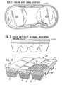
- Figures 1 and 2 of the drawing One of the problems found in the grooved banded belts of the prior art is illustrated in Figures 1 and 2 of the drawing.
- Figure 1 when such a transversely grooved banded belt is utilized for power transmission between a pair of pulleys, a number of different stresses and shearing forces are developed, tending to cause cracking of the belt, particularly from the root of the belt grooves, as illustrated in Figure 2.
- a flexing of the belt occurs at the point where the belt leaves the driven pulley as the belt tends to remain in the annular grooves of the driven pulley both as a result of inertia and friction and, thus, is bent somewhat as it is pulled out of the grooves at a point beyond the tangent between the two pulleys, as illustrated in Figure 1.
- This constant flexing of the belt at this point further tends to produce cracks, such as illustrated in Figure 2.
- the proposed staggered arrangements of the belt grooves have notfully satisfactorily overcome the cracking problems and, thus, the different transversely grooved banded belts of the prior art have limited useful life.
- a power transmission belt (10) having a plurality of V-belt elements (11, 12, 13) retained in longitudinally extending laterally spaced relationship by a tie band (14), there being ° provided in said V-belt elements longitudinally spaced grooves (26) opening away from the tie band, the grooves of respective V-belt elements being substantially aligned transversely of the belt, each of said grooves being defined by an inclined transverse leading surface (28), a reversely inclined transverse trailing surface (29), and a bottom surface (30) in which the inclination of said leading and trailing surfaces to the longitudinal extent of the tie band are different whereby each groove defines an asymmetrical configuration in longitudinal cross-section.
- Embodiments of the present invention provide an improved transversely grooved banded power transmission belt providing substantially improved useful life by effectively overcoming the problems of the above discussed prior art belts. Further, the improved belt construction of the present invention provides enhanced flexibility and strength, permitting the belt to be used on small diameter pulleys while concurrently effectively minimizing noise in the operation of the power transmission means.
- the leading surface of the groove differs from the trailing surface to provide grooves which are longitudinally asymmetrical.
- the leading surface is a planar surface extending at an angle to the longitudinal extent of the belt which is different from that of the planar surface defining the trailing surface of the groove. As a result, the leading surface has a longer extent than that of the trailing surface.
- the grooves of the respective laterally related V-belt elements are aligned in a plurality of sets spaced longitudinally of the belt.
- the leading surfaces of each set of grooves are coplanar and the trailing surfaces of each set of grooves are coplanar.
- the leading surface is inclined at an angle to the longitudinal extent of the belt in the range of approximately 30° to 75°
- the trailing surface is inclined at an angle to the longitudinal extent of the belt in the range of approximately 72° to 84°.
- a difference between the angles of the leading and trailing surfaces relative to the longitudinal extent of the belt is in the range of approximately 2° to 30° in defining the asymmetric configuration of the grooves.
- the invention is advantageously adapted for use in such banded belts of the raw edge type, as well as the wrapped type.
- the invention is further advantageously adapted for use with such banded belts having different types of reinforcement both in the tie band and in the V-belt elements.
- the invention comprehends an improved power transmission belt structure utilizing aligned transverse grooves in the V-belt elements having asymmetrical longitudinal configurations.
- the respective sets of grooves may be spaced uniformly along the longitudinal extent of the belt, or may be randomly differently spaced as desired within the scope of the invention.
- the power transmission belt of the present invention is extremely simple and economical of construction while yet providing long, trouble- free life as a result of the improved crack resistance.
- a power transmission belt generally designated 10 is shown to comprise an improved banded belt structure including a plurality of V-belt elements 11, 12 and 13 retained in side-by-side laterally spaced relationship by a tie band 14.
- the V-belt elements are raw edge elements illustratively formed of elastomeric material wherein the side surfaces 15 are uncovered while the distal, or bottom, surface is provided with a covering fabric layer 16.
- each V-belt element may define a lowermost compression section 17 which illustratively may be provided with transversely extending short fibers 18.
- the V-belt element is provided with a plurality of longitudinally extending tensile cords 19 and outwardly of the tensile cords, the V-beit element defines a tension section 20 which also may be provided with transversely extending short fibers 21.
- the V-belt elements are spaced laterally apart in the belt 10 by the longitudinally extending grooves 22, which, as shown in Figure 3, extend upwardly to the tension section 20. As shown, the grooves 22 define the raw edges 15 between the V-belts.
- Tie band 14 may be provided with suitable fabric reinforcement 23 and, in the illustrated embodiment of Figure 3, the fabric reinforcement is made up of cross yarns, or threads, 24 and 25.
- the fabric reinforcement is made up of cross yarns, or threads, 24 and 25.
- different forms of reinforcement fabric may be utilized in such tie bands.
- the warp threads 24 extend parallel to the longitudinal extent of the belt, whereas the woof threads 25 extend transversely thereto at right angles to the warp threads 24.
- the reinforcing threads extend angularly to the longitudinal extent of the belt and may extend at an angle other than 90° to each other, such as in the range of 95° to 150°.
- the belt 10 is formed primarily of suitable elastomeric material, such as rubber.
- the tie band reinforcing fabric may be formed of wind-shrunk warp threads formed of a synthetic fiber, such as a polyamide or polyester fiber.
- the woof threads may be formed of cotton fibers. In one form, the warp threads are retained parallel to the longitudinal extent of the belt by weak cotton woof threads.
- the invention comprehends the provision of a plurality of transverse grooves in the distal portion of the V-belt elements and, more specifically, in the tension portion thereof.
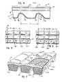
- the grooves of the present invention are arranged in transverse alignment, as illustrated in Figures 5 and 6.
- grooves 26 may be aligned in a first set 27, a second set 27' spaced from first set 27 by a pitch distance P, a third set 27" spaced from second set 27' by the same pitch distance P, and a fourth set 27'" spaced from third set 27" by the same pitch distance.
- the grooves of each set are aligned.
- the sets 27a, 27a', 27a", and 27a'" of the grooves 26, 26', .26", and 26"', respectively, are spaced apart at randomly different distances, such as distances P" P 2 , and P a .
- the grooves of each set are aligned with the other grooves of that set similarly as in the embodiment of Figure 5.
- each groove 26 is defined by an inclined leading surface 28, an inclined trailing surface 29, and a flat bottom surface 30.
- Bottom surface 30 extends parallel to the flatwise extent of the belt.
- Leading surface 28 preferably extends at an angle to the flatwise extent, i.e., angle ⁇ 1 , in the range of approximately 30° to 75°, and in the illustrated embodiment, extends at an angle of 60°.
- Trailing surface 29 preferably extends at an angle to the flatwise extent of the belt, i.e., angle q) 2 in the range of approximately 72° to 84°, and in the illustrated embodiment, extends at an angle of approximately 80°.
- the improved belt structure 10 provides improved long life and crack resistance as compared to the belt structures of the prior art.
- a belt manufactured in accordance with the above disclosed invention was tested against two prior art belt structures. The results of the comparative test are illustrated in the following table:
- Belt A was a belt manufactured in accordance with the above disclosure and as illustrated in Figure 3 of the drawing.
- Belt B was a belt having wrapped V-belt elements without grooves provided therein and utilizing an angled reinforcement in the tie band portion, such as illustrated in Figure 7 of the drawing herein.
- Belt C was a belt similar to Belt A but having grooves such as shown in U.S. Patent 3,626,775 of Kay V. Gentry discussed above.
- the different belts were caused to transmit approximately 100 horsepower, with a driving pulley rotating at approximately 1500 rpm, the driving pulley outside diameter being approximately 355 millimeters, the center-to-center distance of the pulleys being approximately 1079 millimeters, and the effective diameter of the driven pulley being approximately 530 millimeters.
- the belt of the present invention provides a substantial improvement in crack resistance and belt life over that of the prior art belts.
- the V-belt elements 111, 112 and 113 are similar to V-beit elements 11, 12 and 13, but are fully wrapped by a fabric layer 116.
- the configuration illustratively may be one wherein the depth of the grooves 122 between the V-belt elements is approximately 20 millimeters, the depth of the transverse groove 126 is approximately 12 millimeters, the uniform pitch P between the sets of grooves is approximately 40 millimeters, the slant angle of the leading surface is approximately 50°, and the slant angle of the trailing surface is approximately 70°.
- the tie band 114 is formed of a two-ply fabric 123 wherein the wrap cords 123a and 123a' of the respective plies are maintained in association with each other by weak weft fibers 123b and 123b'.
- the warp cords may be formed of suitable strong material, such as cotton, polyamide, polyester, etc., and the woof cords are preferably formed of a relatively weak fine cotton material.
- the cord fabric is preferably rubber coated. As shown, the fabric layers are arranged with the crossing angle of the warp cords 123a, 123a' of the respective layers extending approximately 150° to each other. The angle of the warp cords illustratively is symmetrical about the longitudinal extent of the belt.
- a layer of elastomeric material 131 may be provided between the two fabric layers so as to prevent contact between the cords thereof and thereby effectively minimize stresses in the tie band as the belt passes around the pulleys.
- the invention comprehends that the asymmetrical transverse grooves be arranged in aligned sets and the sets may be uniformly spaced as in Figure 5, or randomly differently spaced as in Figure 6.
- the power transmission belt generally designated 110 of Figure 7 is generally similar to the power transmission belt 10 of Figure 3 and functions in a generally similar manner within the scope of the invention.
- the invention comprehends the provision of all improved power transmission belt wherein the transverse grooves have asymmetrical longi- tudiqal cross sections while being provided in sets of transversely aligned grooves wherein the leading surfaces are coplanar and the trailing surfaces are coplanar with each other.
- the spacing between the sets of grooves may be uniform or different from set to set and further illustratively may be randomly different within the scope of the invention.
- the difference between the angles of the leading and trailing surfaces is in the range of approximately 2° to 30°.
- the invention is advantageously adapted for both raw edge belt design and wrapped belt design and is further advantageously adaptive with a wide range of tie band and V-belt element parameters.
Landscapes
- Engineering & Computer Science (AREA)
- General Engineering & Computer Science (AREA)
- Mechanical Engineering (AREA)
- Textile Engineering (AREA)
- Belt Conveyors (AREA)
- Transmissions By Endless Flexible Members (AREA)
- Ropes Or Cables (AREA)
Claims (10)
Priority Applications (3)
| Application Number | Priority Date | Filing Date | Title |
|---|---|---|---|
| AT80303718T ATE13217T1 (de) | 1980-10-21 | 1980-10-21 | Quergerillter mehrfachtreibriemen. |
| DE8080303718T DE3070624D1 (en) | 1980-10-21 | 1980-10-21 | Cross-grooved banded drive belt |
| EP80303718A EP0050174B1 (de) | 1980-10-21 | 1980-10-21 | Quergerillter Mehrfachtreibriemen |
Applications Claiming Priority (1)
| Application Number | Priority Date | Filing Date | Title |
|---|---|---|---|
| EP80303718A EP0050174B1 (de) | 1980-10-21 | 1980-10-21 | Quergerillter Mehrfachtreibriemen |
Publications (2)
| Publication Number | Publication Date |
|---|---|
| EP0050174A1 EP0050174A1 (de) | 1982-04-28 |
| EP0050174B1 true EP0050174B1 (de) | 1985-05-08 |
Family
ID=8187280
Family Applications (1)
| Application Number | Title | Priority Date | Filing Date |
|---|---|---|---|
| EP80303718A Expired EP0050174B1 (de) | 1980-10-21 | 1980-10-21 | Quergerillter Mehrfachtreibriemen |
Country Status (3)
| Country | Link |
|---|---|
| EP (1) | EP0050174B1 (de) |
| AT (1) | ATE13217T1 (de) |
| DE (1) | DE3070624D1 (de) |
Cited By (2)
| Publication number | Priority date | Publication date | Assignee | Title |
|---|---|---|---|---|
| US10716912B2 (en) | 2015-03-31 | 2020-07-21 | Fisher & Paykel Healthcare Limited | User interface and system for supplying gases to an airway |
| US11324908B2 (en) | 2016-08-11 | 2022-05-10 | Fisher & Paykel Healthcare Limited | Collapsible conduit, patient interface and headgear connector |
Families Citing this family (2)
| Publication number | Priority date | Publication date | Assignee | Title |
|---|---|---|---|---|
| CA1232521A (en) * | 1983-04-20 | 1988-02-09 | Delmar D. Long | Polymeric product having a fabric layer means and method of making the same |
| JP7536731B2 (ja) * | 2020-11-27 | 2024-08-20 | 三ツ星ベルト株式会社 | 結合vベルト |
Citations (8)
| Publication number | Priority date | Publication date | Assignee | Title |
|---|---|---|---|---|
| AT136897B (de) * | 1932-12-23 | 1934-03-26 | Arthur Ing Schuetz | Treibriemen mit Reibungsbelag. |
| US3564933A (en) * | 1969-07-30 | 1971-02-23 | Dayco Corp | Banded power transmission belt |
| US4002082A (en) * | 1975-09-17 | 1977-01-11 | Dayco Corporation | Endless power transmission belt |
| US4011766A (en) * | 1976-02-19 | 1977-03-15 | Dayco Corporation | Endless power transmission belt |
| US4177686A (en) * | 1978-06-15 | 1979-12-11 | Dayco Corporation | Endless power transmission belt |
| EP0010919A1 (de) * | 1978-10-30 | 1980-05-14 | Mitsuboshi Belting Ltd. | Endloser Treibriemen |
| EP0014561A1 (de) * | 1979-02-08 | 1980-08-20 | Mitsuboshi Belting Ltd. | Mehrschichtiger flankenoffener Treibriemen |
| EP0018456A1 (de) * | 1979-05-04 | 1980-11-12 | Mitsuboshi Belting Ltd. | Selbsteinstellender Keilriemen und Verfahren zu dessen Herstellung |
Family Cites Families (1)
| Publication number | Priority date | Publication date | Assignee | Title |
|---|---|---|---|---|
| JPS5545082U (de) * | 1978-09-19 | 1980-03-24 |
-
1980
- 1980-10-21 DE DE8080303718T patent/DE3070624D1/de not_active Expired
- 1980-10-21 EP EP80303718A patent/EP0050174B1/de not_active Expired
- 1980-10-21 AT AT80303718T patent/ATE13217T1/de not_active IP Right Cessation
Patent Citations (8)
| Publication number | Priority date | Publication date | Assignee | Title |
|---|---|---|---|---|
| AT136897B (de) * | 1932-12-23 | 1934-03-26 | Arthur Ing Schuetz | Treibriemen mit Reibungsbelag. |
| US3564933A (en) * | 1969-07-30 | 1971-02-23 | Dayco Corp | Banded power transmission belt |
| US4002082A (en) * | 1975-09-17 | 1977-01-11 | Dayco Corporation | Endless power transmission belt |
| US4011766A (en) * | 1976-02-19 | 1977-03-15 | Dayco Corporation | Endless power transmission belt |
| US4177686A (en) * | 1978-06-15 | 1979-12-11 | Dayco Corporation | Endless power transmission belt |
| EP0010919A1 (de) * | 1978-10-30 | 1980-05-14 | Mitsuboshi Belting Ltd. | Endloser Treibriemen |
| EP0014561A1 (de) * | 1979-02-08 | 1980-08-20 | Mitsuboshi Belting Ltd. | Mehrschichtiger flankenoffener Treibriemen |
| EP0018456A1 (de) * | 1979-05-04 | 1980-11-12 | Mitsuboshi Belting Ltd. | Selbsteinstellender Keilriemen und Verfahren zu dessen Herstellung |
Cited By (5)
| Publication number | Priority date | Publication date | Assignee | Title |
|---|---|---|---|---|
| US10716912B2 (en) | 2015-03-31 | 2020-07-21 | Fisher & Paykel Healthcare Limited | User interface and system for supplying gases to an airway |
| US11904097B2 (en) | 2015-03-31 | 2024-02-20 | Fisher & Paykel Healthcare Limited | User interface and system for supplying gases to an airway |
| US12171946B2 (en) | 2015-03-31 | 2024-12-24 | Fisher & Paykel Healthcare Limited | User interface and system for supplying gases to an airway |
| US12527934B2 (en) | 2015-03-31 | 2026-01-20 | Fisher & Paykel Healthcare Limited | User interface and system for supplying gases to an airway |
| US11324908B2 (en) | 2016-08-11 | 2022-05-10 | Fisher & Paykel Healthcare Limited | Collapsible conduit, patient interface and headgear connector |
Also Published As
| Publication number | Publication date |
|---|---|
| EP0050174A1 (de) | 1982-04-28 |
| DE3070624D1 (en) | 1985-06-13 |
| ATE13217T1 (de) | 1985-05-15 |
Similar Documents
| Publication | Publication Date | Title |
|---|---|---|
| US2831359A (en) | Belting | |
| US4011766A (en) | Endless power transmission belt | |
| US4891040A (en) | Woven fabric belt | |
| US4449959A (en) | Cross grooved banded drive belt | |
| US4838843A (en) | Toothed belt | |
| US5521007A (en) | Fiber cord and power transmission belt using the same | |
| US3996813A (en) | Endless power transmission belt | |
| EP0470836A1 (de) | Keiltreibriemen | |
| US5595284A (en) | Conveyor belt | |
| JPH071054B2 (ja) | 歯付ベルト | |
| EP0014561A1 (de) | Mehrschichtiger flankenoffener Treibriemen | |
| US3656359A (en) | Asymmetric belt construction | |
| US4571230A (en) | Endless power transmission belt having a toothed compression section and method of making the same | |
| US4481051A (en) | Power transmission belt manufacture | |
| US4509938A (en) | Endless power transmission belt having a toothed compression section and method of making the same | |
| KR20030074712A (ko) | 동력전달용 무한벨트 | |
| EP0050174B1 (de) | Quergerillter Mehrfachtreibriemen | |
| EP0060713A1 (de) | Kielriemen | |
| US4579547A (en) | V-belt | |
| EP0109990B1 (de) | Keilriemenaufbau | |
| CA1158071A (en) | Cross-grooved banded drive belt | |
| EP0040908B1 (de) | Kraftübertragungsriemen | |
| US4504256A (en) | Variable V-belt | |
| US4990125A (en) | Flat belt, belt drive, and method | |
| US4022071A (en) | Steel cord belt reinforced transmission belt |
Legal Events
| Date | Code | Title | Description |
|---|---|---|---|
| PUAI | Public reference made under article 153(3) epc to a published international application that has entered the european phase |
Free format text: ORIGINAL CODE: 0009012 |
|
| AK | Designated contracting states |
Designated state(s): AT CH DE FR GB IT NL SE |
|
| RBV | Designated contracting states (corrected) |
Designated state(s): AT CH DE FR GB IT LI LU NL SE |
|
| RBV | Designated contracting states (corrected) |
Designated state(s): AT CH DE FR GB IT LI NL SE |
|
| 17P | Request for examination filed |
Effective date: 19821019 |
|
| ITF | It: translation for a ep patent filed | ||
| GRAA | (expected) grant |
Free format text: ORIGINAL CODE: 0009210 |
|
| AK | Designated contracting states |
Designated state(s): AT CH DE FR GB IT LI NL SE |
|
| REF | Corresponds to: |
Ref document number: 13217 Country of ref document: AT Date of ref document: 19850515 Kind code of ref document: T |
|
| REF | Corresponds to: |
Ref document number: 3070624 Country of ref document: DE Date of ref document: 19850613 |
|
| ET | Fr: translation filed | ||
| PLBE | No opposition filed within time limit |
Free format text: ORIGINAL CODE: 0009261 |
|
| STAA | Information on the status of an ep patent application or granted ep patent |
Free format text: STATUS: NO OPPOSITION FILED WITHIN TIME LIMIT |
|
| 26N | No opposition filed | ||
| PG25 | Lapsed in a contracting state [announced via postgrant information from national office to epo] |
Ref country code: SE Effective date: 19871022 |
|
| PG25 | Lapsed in a contracting state [announced via postgrant information from national office to epo] |
Ref country code: LI Effective date: 19871031 Ref country code: CH Effective date: 19871031 |
|
| PGFP | Annual fee paid to national office [announced via postgrant information from national office to epo] |
Ref country code: NL Payment date: 19871031 Year of fee payment: 8 |
|
| PG25 | Lapsed in a contracting state [announced via postgrant information from national office to epo] |
Ref country code: FR Free format text: LAPSE BECAUSE OF NON-PAYMENT OF DUE FEES Effective date: 19880630 |
|
| REG | Reference to a national code |
Ref country code: CH Ref legal event code: PL |
|
| REG | Reference to a national code |
Ref country code: FR Ref legal event code: ST |
|
| PG25 | Lapsed in a contracting state [announced via postgrant information from national office to epo] |
Ref country code: GB Effective date: 19881021 |
|
| PG25 | Lapsed in a contracting state [announced via postgrant information from national office to epo] |
Ref country code: NL Effective date: 19890501 |
|
| NLV4 | Nl: lapsed or anulled due to non-payment of the annual fee | ||
| GBPC | Gb: european patent ceased through non-payment of renewal fee | ||
| EUG | Se: european patent has lapsed |
Ref document number: 80303718.3 Effective date: 19880707 |
|
| PGFP | Annual fee paid to national office [announced via postgrant information from national office to epo] |
Ref country code: AT Payment date: 19970923 Year of fee payment: 18 |
|
| PGFP | Annual fee paid to national office [announced via postgrant information from national office to epo] |
Ref country code: DE Payment date: 19970925 Year of fee payment: 18 |
|
| PG25 | Lapsed in a contracting state [announced via postgrant information from national office to epo] |
Ref country code: AT Free format text: LAPSE BECAUSE OF NON-PAYMENT OF DUE FEES Effective date: 19981021 |
|
| PG25 | Lapsed in a contracting state [announced via postgrant information from national office to epo] |
Ref country code: DE Free format text: LAPSE BECAUSE OF NON-PAYMENT OF DUE FEES Effective date: 19990803 |