EP0050174A1 - Cross-grooved banded drive belt - Google Patents
Cross-grooved banded drive belt Download PDFInfo
- Publication number
- EP0050174A1 EP0050174A1 EP80303718A EP80303718A EP0050174A1 EP 0050174 A1 EP0050174 A1 EP 0050174A1 EP 80303718 A EP80303718 A EP 80303718A EP 80303718 A EP80303718 A EP 80303718A EP 0050174 A1 EP0050174 A1 EP 0050174A1
- Authority
- EP
- European Patent Office
- Prior art keywords
- belt
- grooves
- power transmission
- elements
- transmission belt
- Prior art date
- Legal status (The legal status is an assumption and is not a legal conclusion. Google has not performed a legal analysis and makes no representation as to the accuracy of the status listed.)
- Granted
Links
Images
Classifications
-
- F—MECHANICAL ENGINEERING; LIGHTING; HEATING; WEAPONS; BLASTING
- F16—ENGINEERING ELEMENTS AND UNITS; GENERAL MEASURES FOR PRODUCING AND MAINTAINING EFFECTIVE FUNCTIONING OF MACHINES OR INSTALLATIONS; THERMAL INSULATION IN GENERAL
- F16G—BELTS, CABLES, OR ROPES, PREDOMINANTLY USED FOR DRIVING PURPOSES; CHAINS; FITTINGS PREDOMINANTLY USED THEREFOR
- F16G5/00—V-belts, i.e. belts of tapered cross-section
- F16G5/04—V-belts, i.e. belts of tapered cross-section made of rubber
- F16G5/06—V-belts, i.e. belts of tapered cross-section made of rubber with reinforcement bonded by the rubber
- F16G5/08—V-belts, i.e. belts of tapered cross-section made of rubber with reinforcement bonded by the rubber with textile reinforcement
-
- F—MECHANICAL ENGINEERING; LIGHTING; HEATING; WEAPONS; BLASTING
- F16—ENGINEERING ELEMENTS AND UNITS; GENERAL MEASURES FOR PRODUCING AND MAINTAINING EFFECTIVE FUNCTIONING OF MACHINES OR INSTALLATIONS; THERMAL INSULATION IN GENERAL
- F16G—BELTS, CABLES, OR ROPES, PREDOMINANTLY USED FOR DRIVING PURPOSES; CHAINS; FITTINGS PREDOMINANTLY USED THEREFOR
- F16G5/00—V-belts, i.e. belts of tapered cross-section
- F16G5/20—V-belts, i.e. belts of tapered cross-section with a contact surface of special shape, e.g. toothed
Definitions
- This invention relates to power transmission belts and in particular to cross-grooved banded belts.
- the leading surface of the groove differs from the trailing surface.
- the leading surface is a planar surface extending at an angle to the longitudinal extent of the belt which is different from that of the planar surface defining the trailing surface of the groove. Resultingly, the leading surface has a longer extent than that of the trailing surface.
- the grooves of the respective laterally related V-belt elements are aligned in a plurality of sets spaced longitudinally of the belt.
- the leading surfaces of each set of grooves are coplanar and the trailing surfaces of each set of grooves are coplanar.
- the leading surface is inclined at an angle to the longitudinal extent of the belt in the range of approximately 30° to 75°
- the trailing surface is inclined at an angle to the longitudinal extent of the belt in the range of approximately 72° to 84°.
- the power transmission belt of the present invention is extremely simple and economical of construction while yet providing long, trouble-free life as a result of the improved crack resistance.
- the V-belt elements are raw edge elements illustratively formed of elastomeric material wherein the side surfaces 15 are uncovered while the distal, or bottom, surface is provided with a covering fabric layer 16.
- the belt 10 is formed primarily of suitable elastomeric material, such as rubber.
- the tie band reinforcing fabric may be formed of wind-shrunk warp threads formed of a synthetic fiber, such as a polyamide or polyester fiber.
- the woof threads may be formed of cotton fibers. In one form, the warp threads are retained parallel to the longitudinal extent of the belt by weak cotton woof threads.
- the sets 27a, 27a', 27a", and 27a'" of the grooves 26, 26', 26", and 26'", respectively, are spaced apart at randomly different distances, such as distances P 1 , P 2 , and P 3 .
- the grooves of each set are aligned with the other grooves of that set similarly as in the embodiment of Figure 5.
- Belt A was a belt manufactured in accordance with the above disclosure and as illustrated in Figure 3 of the drawing.
- Belt B was a belt having wrapped V-belt elements without grooves provided therein and utilizing an angled reinforcement in the tie band portion, such as illustrated in Figure 7 of the drawing herein.
- Belt C was a belt similar to Belt A but having grooves such as shown in U. S. Patent 3,626,775 of Kay V. Gentry discussed above.
- the tie band 114 is formed of a two-ply fabric 123 wherein the wrap cords 123a and 123a' of the respective plies are maintained in association with each other by weak weft fibers 123b and 123b'.
- the warp cords may be formed of suitable strong material, such as cotton, polyamide, polyester, etc., and the woof cords.are preferably formed of a relatively weak fine cotton material.
- the cord fabric is preferably rubber coated. As shown, the fabric layers are arranged with the crossing angle of the warp cords 123a,123a' of the respective layers extending approximately 150° to each other. The angle of the warp cords illustratively is symmetrical about the longitudinal extent of the belt.
- a layer of elastomeric material 131 may be provided between the two fabric layers so as to prevent contact between the cords thereof and thereby effectively minimize stresses in the tie band as the belt passes around the pulleys.
- the invention comprehends that the asymmetrical transverse grooves be arranged in aligned sets and the sets may be uniformly spaced as in Figure 5, or randomly differently spaced as in Figure 6.
- the power transmission belt generally designated 110 of Figure 7 is generally similar to the power transmission belt 10 of Figure 3 and functions in a generally similar manner within the scope of the invention.
- the invention comprehends the provision of an improved power transmission belt wherein the transverse grooves have asymmetrical longitudinal cross sections while being provided in sets of transversely aligned grooves wherein the leading surfaces are coplanar and the trailing surfaces are coplanar with each other.
- the spacing between the sets of grooves may be uniform or different from set to set and further illustratively may be randomly different within the scope of the invention.
- the difference between the angles of the leading and trailing surfaces is in the range of approximately 2° to 30°.
- the invention is advantageously adapted for both raw edge belt design and wrapped belt design and is further advantageously adaptive with a wide range of tie band and V-belt element parameters.
Abstract
Description
- This invention relates to power transmission belts and in particular to cross-grooved banded belts.
- In one conventional form of power transmission belt, a plurality of V-belt elements are retained in laterally spaced, parallel arrangement by a tie band. To provide improved flexibility in such tie band belts, transverse grooves have been provided in the distal portions of the V-belt elements.' The present invention is concerned with an improved arrangement of the grooves of such a grooved banded belt manufacture.
- More specifically, one form of cross-grooved banded belt is illustrated in U. S. Letters Patent 2,802,511 of Dale L. Waugh. As shown therein, the V-belt elements are provided with transverse grooves which alternate from rib to rib in a staggered manner. Waugh teaches that the grooves should be disaligned so as to provide a greater area of contact between the belt and pulley at any given instant than would be provided if the grooves all lay in transverse alignment.
- Donald E. Clinkenbeard, in U.S. Letters Patent -3,564,933, shows a banded transmission belt wherein the V-belt elements are of the wrapped type and the tie band is provided with a bias cut reinforcing fabric.
- K. V. Gentry shows, in U. S. Letters Patent 3,626,775, a V-belt element having longitudinally symmetrical notches.
- In U. S. Letters Patent 3,853,017 of Jack D. White, Jr., et al, a power transmission belt is disclosed wherein the tie band is reinforced by a knitted fabric layer.
- Delyn M. Stork discloses, in U.S. Letters Patent 3,948,113, a power transmission belt wherein the V-belt elements are provided with transverse grooves which are illustrated as being segmentally cylindrical.
- In U. S. Letters Patent 4,011,766, Dale L. Waugh shows a power transmission belt similar to that of the Waugh patent 2,802,511 discussed above wherein the V-belt elements are provided with grooves which are staggered in the respective V-belt elements. The patentee again requires the staggered relation of the equal- sized teeth of the V-belt elements to assure that the belt is free of hinge points and points out that if the grooves were in transverse alignment between the V-belt elements, they would cause a reduced thickness hinge line to be formed in the belt which would weaken the belt.
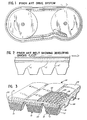
- One of the problems found in the grooved banded belts of the prior art is illustrated in Figures 1 and 2 of the drawing. Thus, as shown in Figure 1, when such a transversely grooved banded belt is utilized for power transmission between a pair of pulleys, a number of different stresses and shearing forces are developed, tending to cause cracking of the belt, particularly from the root of the belt grooves, as illustrated in Figure 2. As further shown in Figure 1, a flexing of the belt occurs at the point where the belt leaves the driven pulley as the belt tends to remain in the annular grooves of the driven pulley both as a result of inertia and friction and, thus, is bent somewhat as it is pulled out of the grooves at a point beyond the tangent between the two pulleys, as illustrated in Figure 1. This constant flexing of the belt at this point further tends to produce cracks, such as illustrated in Figure 2. The proposed staggered arrangements of the belt grooves have not fully satisfactorily overcome the cracking problems and, thus, the different transversely grooved banded belts of the prior art have limited useful life.
- The present invention comprehends an improved transversely grooved banded power transmission belt providing substantially improved useful life by effectively overcoming the problems of the above discussed prior art belts. Further, the improved belt construction of the present invention provides enhanced flexibility and strength, permitting the belt to be used on small diameter pulleys while concurrently effectively minimizing noise in the operation of the power transmission means.
- In one broad aspect, the invention comprehends the provision of such a transversely grooved banded belt wherein the grooves are longitudinally asymmetrical.
- Thus, in the illustrated embodiment, the leading surface of the groove differs from the trailing surface. In the illustrated embodiment, the leading surface is a planar surface extending at an angle to the longitudinal extent of the belt which is different from that of the planar surface defining the trailing surface of the groove. Resultingly, the leading surface has a longer extent than that of the trailing surface.
- In the illustrated embodiment, the grooves of the respective laterally related V-belt elements are aligned in a plurality of sets spaced longitudinally of the belt. Thus, the leading surfaces of each set of grooves are coplanar and the trailing surfaces of each set of grooves are coplanar.
- In the disclosed embodiment, the leading surface is inclined at an angle to the longitudinal extent of the belt in the range of approximately 30° to 75°, and the trailing surface is inclined at an angle to the longitudinal extent of the belt in the range of approximately 72° to 84°. Resultingly, a difference between the angles of the leading and trailing surfaces relative to the longitudinal extent of the belt as in the range of approximately 2° to 30° in defining the asymmetric configuration of the grooves.
- The invention is advantageously adapted for use in such banded belts of the raw edge type, as well as the wrapped type. The invention is further advantageously adapted for use with such banded belts having different types of reinforcement both in the tie band and in the V-belt elements.
- Thus, the invention comprehends an improved power transmission belt structure utilizing aligned transverse grooves in the V-belt elements having asymmetrical longitudinal configurations. The respective sets of grooves may be spaced uniformly along the longitudinal extent of the belt, or may be randomly differently spaced as desired within the scope of the invention.
- The power transmission belt of the present invention is extremely simple and economical of construction while yet providing long, trouble-free life as a result of the improved crack resistance.
- Other features and advantages of the invention will be apparent from the following description taken in connection with the accompanying drawing wherein:
- Figure 1 is a schematic illustration of a power transmission utilizing a transversely grooved belt illustrating the stresses and forces acting on the belt during power transmission which tend to cause failure of the belt;
- Figure 2 is a fragmentary longitudinal, enlarged section illustrating the formation of cracks in the belt resulting from the induced stresses;
- Figure 3 is a fragmentary perspective sectional view of one form of power transmission belt embodying the invention;
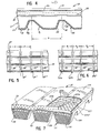
- Figure 4 is a fragmentary enlarged longitudinal section of the embodiment of Figure 3;
- Figure 5 is a fragmentary bottom plan view thereof;
- Figure 6 is a fragmentary bottom plan view of a modified form thereof; and
- Figure 7 is a fragmentary perspective view of another modified form of power transmission belt embodying the invention.
- In the exemplary embodiments of the invention as disclosed in the drawing, a power transmission belt generally designated 10 is shown to comprise an improved banded belt structure including a plurality of V-
belt elements tie band 14. - In the embodiment of Figure 3, the V-belt elements are raw edge elements illustratively formed of elastomeric material wherein the
side surfaces 15 are uncovered while the distal, or bottom, surface is provided with acovering fabric layer 16. - As further illustrated in Figure 3, each V-belt element may define a
lowermost compression section 17 which illustratively may be provided with transversely extendingshort fibers 18. Outwardly of the compression section, the V-belt element is provided with a plurality of longitudinally extendingtensile cords 19 and outwardly of the tensile cords, the V-belt element defines atension section 20 which also may be provided with transversely extendingshort fibers 21. - The V-belt elements are spaced laterally apart in the
belt 10 by the longitudinally extending-grooves 22, which, as shown in Figure 3, extend upwardly to thetension section 20. As shown, thegrooves 22 define theraw edges 15 between the V-belts. -
Tie band 14 may be provided withsuitable fabric reinforcement 23 and, in the illustrated embodiment of Figure 3, the fabric reinforcement is made up of cross yarns, or threads, 24 and 25. As is well known to those in the art, different forms of reinforcement fabric may be utilized in such tie bands. In the illustrated form, thewarp threads 24 extend parallel to the longitudinal extent of the belt, whereas thewoof threads 25 extend transversely thereto at right angles to thewarp threads 24. In another suitable form for such reinforcing fabric, the reinforcing threads extend angularly to the longitudinal extent of the belt and may extend at an angle other than 90° to each other, such as in the range of 95° to 150°. - The
belt 10 is formed primarily of suitable elastomeric material, such as rubber. The tie band reinforcing fabric may be formed of wind-shrunk warp threads formed of a synthetic fiber, such as a polyamide or polyester fiber. The woof threads may be formed of cotton fibers. In one form, the warp threads are retained parallel to the longitudinal extent of the belt by weak cotton woof threads. - As indicated briefly above, the invention comprehends the provision of a plurality of transverse grooves in the distal portion of the V-belt elements and, more specifically, in the tension portion thereof. The grooves of the present invention are arranged in transverse alignment, as illustrated in Figures 5 and 6. As shown in Figure 5,
grooves 26 may be aligned in afirst set 27, a second set 27' spaced fromfirst set 27 by a pitch distance P, athird set 27" spaced from second set 27' by the same pitch distance P, and a fourth set 27'" spaced fromthird set 27" by the same pitch distance. The grooves of each set are aligned. - In Figure 6, the
sets grooves - Referring now more specifically to Figure 4, each
groove 26 is defined by an inclined leading surface 28, an inclinedtrailing surface 29, and aflat bottom surface 30.Bottom surface 30 extends parallel to the flatwise extent of the belt. Leading surface 28 preferably extends at an angle to the flatwise extent, i.e. angle φ1, in the range of approximately 30° to 75°, and in the illustrated embodiment, extends at an angle of 60°.Trailing surface 29 preferably extends at an angle to the flatwise extent of the belt, i.e., angle ϕ2 in the range of approximately 72° to 84°, and in the illustrated embodiment, extends at an angle of approximately 80°. - As indicated above, the
improved belt structure 10 provides improved long life and crack resistance .as compared to the belt structures of the prior art. Illustratively, a belt manufactured in accordance with the above disclosed invention was tested against two prior art belt structures. The results of the comparative test are illustrated in the following table:
- Belt A was a belt manufactured in accordance with the above disclosure and as illustrated in Figure 3 of the drawing. Belt B was a belt having wrapped V-belt elements without grooves provided therein and utilizing an angled reinforcement in the tie band portion, such as illustrated in Figure 7 of the drawing herein. Belt C was a belt similar to Belt A but having grooves such as shown in U. S. Patent 3,626,775 of Kay V. Gentry discussed above.
- In conducting the comparative tests, the different belts were caused to transmit approximately 100 horsepower, with a driving pulley rotating at approximately 1500 rpm, the driving pulley outside diameter being approximately 355 millimeters, the center-to- center distance of the pulleys being approximately 1079 millimeters, and the effective diameter of the driven pulley being approximately 530 millimeters. As can be seen from the table, the belt of the present invention provides a substantial improvement in crack resistance and belt life over that of the prior art belts.
- In a modified form of the invention as illustrated in Figure 7, the V-
belt elements belt elements fabric layer 116. In this embodiment, the configuration illustratively may be one wherein the depth of thegrooves 122 between the V-belt elements is approximately 20 millimeters, the depth of thetransverse groove 126 is approximately 12 millimeters, the uniform pitch P between the sets of grooves is approximately 40 millimeters, the slant angle of the leading surface is approximately 50°, and the slant angle of the trailing surface is approximately 70°. - Further in the embodiment of Figure 7, the
tie band 114 is formed of a two-ply fabric 123 wherein the wrap cords 123a and 123a' of the respective plies are maintained in association with each other byweak weft fibers elastomeric material 131 may be provided between the two fabric layers so as to prevent contact between the cords thereof and thereby effectively minimize stresses in the tie band as the belt passes around the pulleys. As in the embodiment of Figure 3, the invention comprehends that the asymmetrical transverse grooves be arranged in aligned sets and the sets may be uniformly spaced as in Figure 5, or randomly differently spaced as in Figure 6. - Thus, the power transmission belt generally designated 110 of Figure 7 is generally similar to the
power transmission belt 10 of Figure 3 and functions in a generally similar manner within the scope of the invention. - Thus, the invention comprehends the provision of an improved power transmission belt wherein the transverse grooves have asymmetrical longitudinal cross sections while being provided in sets of transversely aligned grooves wherein the leading surfaces are coplanar and the trailing surfaces are coplanar with each other. The spacing between the sets of grooves may be uniform or different from set to set and further illustratively may be randomly different within the scope of the invention. In the illustrated embodiment, the difference between the angles of the leading and trailing surfaces is in the range of approximately 2° to 30°. As indicated above, the invention is advantageously adapted for both raw edge belt design and wrapped belt design and is further advantageously adaptive with a wide range of tie band and V-belt element parameters.
- The foregoing disclosure of specific embodiments is illustrative of the broad inventive concepts comprehended by the invention.
Claims (10)
Priority Applications (3)
| Application Number | Priority Date | Filing Date | Title |
|---|---|---|---|
| DE8080303718T DE3070624D1 (en) | 1980-10-21 | 1980-10-21 | Cross-grooved banded drive belt |
| AT80303718T ATE13217T1 (en) | 1980-10-21 | 1980-10-21 | CROSS-GROOVED MULTIPLE BELT. |
| EP80303718A EP0050174B1 (en) | 1980-10-21 | 1980-10-21 | Cross-grooved banded drive belt |
Applications Claiming Priority (1)
| Application Number | Priority Date | Filing Date | Title |
|---|---|---|---|
| EP80303718A EP0050174B1 (en) | 1980-10-21 | 1980-10-21 | Cross-grooved banded drive belt |
Publications (2)
| Publication Number | Publication Date |
|---|---|
| EP0050174A1 true EP0050174A1 (en) | 1982-04-28 |
| EP0050174B1 EP0050174B1 (en) | 1985-05-08 |
Family
ID=8187280
Family Applications (1)
| Application Number | Title | Priority Date | Filing Date |
|---|---|---|---|
| EP80303718A Expired EP0050174B1 (en) | 1980-10-21 | 1980-10-21 | Cross-grooved banded drive belt |
Country Status (3)
| Country | Link |
|---|---|
| EP (1) | EP0050174B1 (en) |
| AT (1) | ATE13217T1 (en) |
| DE (1) | DE3070624D1 (en) |
Cited By (1)
| Publication number | Priority date | Publication date | Assignee | Title |
|---|---|---|---|---|
| EP0140952A1 (en) * | 1983-04-20 | 1985-05-15 | DAYCO PRODUCTS, Inc. | Method of making a polymeric product having a fabric layer means, and belt comprising the polymeric product |
Families Citing this family (2)
| Publication number | Priority date | Publication date | Assignee | Title |
|---|---|---|---|---|
| JP6843759B2 (en) | 2015-03-31 | 2021-03-17 | フィッシャー アンド ペイケル ヘルスケア リミテッド | User interface and system for supplying gas to the airways |
| CN109803707B (en) | 2016-08-11 | 2022-03-22 | 费雪派克医疗保健有限公司 | Collapsible catheter, patient interface and headgear connector |
Citations (1)
| Publication number | Priority date | Publication date | Assignee | Title |
|---|---|---|---|---|
| EP0009389A1 (en) * | 1978-09-19 | 1980-04-02 | Mitsuboshi Belting Ltd. | Endless power transmission belt |
Family Cites Families (8)
| Publication number | Priority date | Publication date | Assignee | Title |
|---|---|---|---|---|
| AT136897B (en) * | 1932-12-23 | 1934-03-26 | Arthur Ing Schuetz | Drive belt with friction lining. |
| US3564933A (en) * | 1969-07-30 | 1971-02-23 | Dayco Corp | Banded power transmission belt |
| US4002082A (en) * | 1975-09-17 | 1977-01-11 | Dayco Corporation | Endless power transmission belt |
| US4011766A (en) * | 1976-02-19 | 1977-03-15 | Dayco Corporation | Endless power transmission belt |
| US4177686A (en) * | 1978-06-15 | 1979-12-11 | Dayco Corporation | Endless power transmission belt |
| JPS5724997Y2 (en) * | 1978-10-30 | 1982-05-31 | ||
| JPS5757243Y2 (en) * | 1979-02-08 | 1982-12-08 | ||
| DE2965789D1 (en) * | 1979-05-04 | 1983-08-04 | Mitsuboshi Belting Ltd | Self-adjusting v-belt and method of manufacturing the same |
-
1980
- 1980-10-21 EP EP80303718A patent/EP0050174B1/en not_active Expired
- 1980-10-21 DE DE8080303718T patent/DE3070624D1/en not_active Expired
- 1980-10-21 AT AT80303718T patent/ATE13217T1/en not_active IP Right Cessation
Patent Citations (1)
| Publication number | Priority date | Publication date | Assignee | Title |
|---|---|---|---|---|
| EP0009389A1 (en) * | 1978-09-19 | 1980-04-02 | Mitsuboshi Belting Ltd. | Endless power transmission belt |
Cited By (2)
| Publication number | Priority date | Publication date | Assignee | Title |
|---|---|---|---|---|
| EP0140952A1 (en) * | 1983-04-20 | 1985-05-15 | DAYCO PRODUCTS, Inc. | Method of making a polymeric product having a fabric layer means, and belt comprising the polymeric product |
| EP0140952A4 (en) * | 1983-04-20 | 1987-11-23 | Dayco Corp | Method of making a polymeric product having a fabric layer means, and belt comprising the polymeric product. |
Also Published As
| Publication number | Publication date |
|---|---|
| ATE13217T1 (en) | 1985-05-15 |
| DE3070624D1 (en) | 1985-06-13 |
| EP0050174B1 (en) | 1985-05-08 |
Similar Documents
| Publication | Publication Date | Title |
|---|---|---|
| US4838843A (en) | Toothed belt | |
| US4891040A (en) | Woven fabric belt | |
| US2831359A (en) | Belting | |
| US4449959A (en) | Cross grooved banded drive belt | |
| US5244436A (en) | Power transmission V-belt | |
| US3996813A (en) | Endless power transmission belt | |
| CN111630299A (en) | Belt type friction power conveyor belt | |
| US4299587A (en) | V-Belt | |
| US5521007A (en) | Fiber cord and power transmission belt using the same | |
| US6827660B2 (en) | Endless power transmission belt | |
| EP0147054A1 (en) | Toothed belt and method with reinforcement cord | |
| US4481051A (en) | Power transmission belt manufacture | |
| US4571230A (en) | Endless power transmission belt having a toothed compression section and method of making the same | |
| US4509938A (en) | Endless power transmission belt having a toothed compression section and method of making the same | |
| EP0060713A1 (en) | A V-belt | |
| EP0050174B1 (en) | Cross-grooved banded drive belt | |
| EP0109990B1 (en) | V-belt structure | |
| EP0040908B1 (en) | Power transmission belt | |
| CA1158071A (en) | Cross-grooved banded drive belt | |
| US4990125A (en) | Flat belt, belt drive, and method | |
| US4504256A (en) | Variable V-belt | |
| US4022071A (en) | Steel cord belt reinforced transmission belt | |
| US4003269A (en) | Power transmission belt | |
| EP0467630A2 (en) | V-ribbed belt | |
| JPS5824037Y2 (en) | multi rib belt |
Legal Events
| Date | Code | Title | Description |
|---|---|---|---|
| PUAI | Public reference made under article 153(3) epc to a published international application that has entered the european phase |
Free format text: ORIGINAL CODE: 0009012 |
|
| AK | Designated contracting states |
Designated state(s): AT CH DE FR GB IT NL SE |
|
| RBV | Designated contracting states (corrected) |
Designated state(s): AT CH DE FR GB IT LI LU NL SE |
|
| RBV | Designated contracting states (corrected) |
Designated state(s): AT CH DE FR GB IT LI NL SE |
|
| 17P | Request for examination filed |
Effective date: 19821019 |
|
| ITF | It: translation for a ep patent filed |
Owner name: JACOBACCI & PERANI S.P.A. |
|
| GRAA | (expected) grant |
Free format text: ORIGINAL CODE: 0009210 |
|
| AK | Designated contracting states |
Designated state(s): AT CH DE FR GB IT LI NL SE |
|
| REF | Corresponds to: |
Ref document number: 13217 Country of ref document: AT Date of ref document: 19850515 Kind code of ref document: T |
|
| REF | Corresponds to: |
Ref document number: 3070624 Country of ref document: DE Date of ref document: 19850613 |
|
| ET | Fr: translation filed | ||
| PLBE | No opposition filed within time limit |
Free format text: ORIGINAL CODE: 0009261 |
|
| STAA | Information on the status of an ep patent application or granted ep patent |
Free format text: STATUS: NO OPPOSITION FILED WITHIN TIME LIMIT |
|
| 26N | No opposition filed | ||
| PG25 | Lapsed in a contracting state [announced via postgrant information from national office to epo] |
Ref country code: SE Effective date: 19871022 |
|
| PG25 | Lapsed in a contracting state [announced via postgrant information from national office to epo] |
Ref country code: LI Effective date: 19871031 Ref country code: CH Effective date: 19871031 |
|
| PGFP | Annual fee paid to national office [announced via postgrant information from national office to epo] |
Ref country code: NL Payment date: 19871031 Year of fee payment: 8 |
|
| PG25 | Lapsed in a contracting state [announced via postgrant information from national office to epo] |
Ref country code: FR Free format text: LAPSE BECAUSE OF NON-PAYMENT OF DUE FEES Effective date: 19880630 |
|
| REG | Reference to a national code |
Ref country code: CH Ref legal event code: PL |
|
| REG | Reference to a national code |
Ref country code: FR Ref legal event code: ST |
|
| PG25 | Lapsed in a contracting state [announced via postgrant information from national office to epo] |
Ref country code: GB Effective date: 19881021 |
|
| PG25 | Lapsed in a contracting state [announced via postgrant information from national office to epo] |
Ref country code: NL Effective date: 19890501 |
|
| NLV4 | Nl: lapsed or anulled due to non-payment of the annual fee | ||
| GBPC | Gb: european patent ceased through non-payment of renewal fee | ||
| EUG | Se: european patent has lapsed |
Ref document number: 80303718.3 Effective date: 19880707 |
|
| PGFP | Annual fee paid to national office [announced via postgrant information from national office to epo] |
Ref country code: AT Payment date: 19970923 Year of fee payment: 18 |
|
| PGFP | Annual fee paid to national office [announced via postgrant information from national office to epo] |
Ref country code: DE Payment date: 19970925 Year of fee payment: 18 |
|
| PG25 | Lapsed in a contracting state [announced via postgrant information from national office to epo] |
Ref country code: AT Free format text: LAPSE BECAUSE OF NON-PAYMENT OF DUE FEES Effective date: 19981021 |
|
| PG25 | Lapsed in a contracting state [announced via postgrant information from national office to epo] |
Ref country code: DE Free format text: LAPSE BECAUSE OF NON-PAYMENT OF DUE FEES Effective date: 19990803 |