EP0049984B1 - Draught deflector for vehicles - Google Patents
Draught deflector for vehicles Download PDFInfo
- Publication number
- EP0049984B1 EP0049984B1 EP19810304588 EP81304588A EP0049984B1 EP 0049984 B1 EP0049984 B1 EP 0049984B1 EP 19810304588 EP19810304588 EP 19810304588 EP 81304588 A EP81304588 A EP 81304588A EP 0049984 B1 EP0049984 B1 EP 0049984B1
- Authority
- EP
- European Patent Office
- Prior art keywords
- panel portion
- hinge
- deflector
- panel
- hinges
- Prior art date
- Legal status (The legal status is an assumption and is not a legal conclusion. Google has not performed a legal analysis and makes no representation as to the accuracy of the status listed.)
- Expired
Links
- 229910000639 Spring steel Inorganic materials 0.000 description 1
- WHGYBXFWUBPSRW-FOUAGVGXSA-N beta-cyclodextrin Chemical compound OC[C@H]([C@H]([C@@H]([C@H]1O)O)O[C@H]2O[C@@H]([C@@H](O[C@H]3O[C@H](CO)[C@H]([C@@H]([C@H]3O)O)O[C@H]3O[C@H](CO)[C@H]([C@@H]([C@H]3O)O)O[C@H]3O[C@H](CO)[C@H]([C@@H]([C@H]3O)O)O[C@H]3O[C@H](CO)[C@H]([C@@H]([C@H]3O)O)O3)[C@H](O)[C@H]2O)CO)O[C@@H]1O[C@H]1[C@H](O)[C@@H](O)[C@@H]3O[C@@H]1CO WHGYBXFWUBPSRW-FOUAGVGXSA-N 0.000 description 1
Images

Classifications
-
- B—PERFORMING OPERATIONS; TRANSPORTING
- B60—VEHICLES IN GENERAL
- B60J—WINDOWS, WINDSCREENS, NON-FIXED ROOFS, DOORS, OR SIMILAR DEVICES FOR VEHICLES; REMOVABLE EXTERNAL PROTECTIVE COVERINGS SPECIALLY ADAPTED FOR VEHICLES
- B60J7/00—Non-fixed roofs; Roofs with movable panels, e.g. rotary sunroofs
- B60J7/22—Wind deflectors for open roofs
Definitions
- This invention relates to draught deflectors for passenger vehicles having a longitudinal opening in the roof adapted to be closed by a sliding or folding panel.
- Deflectors for this purpose commonly consist of a transverse member adapted to be hinged to a stationary cross member at the front end of the roof opening so as to be movable between an inoperative position below the closed roof panel and an operative position in which it extends rearwardly and upwardly from its hinges to deflect air flow upwardly over the windscreen and front part of the car away from the roof opening.
- Patent specifications GB-A-1070018 and GB-A-1353150 disclose draught deflectors of this type comprising a rigid panel attached to said stationary transverse member by three hinges, one at each end and one at the centre. Because on most vehicles, the stationary transverse member has a substantial curvature in the transverse direction of the vehicle, the connection between the panel and the centre hinge is arranged to permit relative sliding movement in a direction perpendicular to the hinge axis as the deflector is moved between its operative and inoperative positions. However, the curvature of the transverse member makes it difficult to ensure that there is no gap between the hinge edge of the deflector and the adjacent vehicle roof. Any such gap can result in the production of undesirable wind noise.
- a draught deflector for an opening roof in a motor vehicle comprising a panel extending across the front of the vehicle roof opening and three spaced hinges, one part of each hinge being adapted for connection to a stationary transverse member extending across the front of the roof opening and the other part of each hinge being connected to the panel which has a rigid panel portion with an exposed edge forming the trailing edge of the deflector as known from the patent specification GB-A-1353150.
- the panel has a flexible panel portion overlying part of the rigid panel portion and being movable relative to the rigid panel portion in a direction perpendicular to said trailing edge, said other part of at least one of the three hinges being connected to the flexible panel portion.
- the panel portions are interconnected so as to inhibit relative movement at locations adjacent to the end hinges.
- an opening roof for a motor vehicle includes a frame 10 bounding the aperture in the vehicle roof.
- a draught deflector 12 in accordance with the invention is mounted on the front transverse member 14 of the frame 10.
- the deflector 12 consists of a panel 16 and U-shaped member 18 which is slightly shorter than the panel 16 and has each of its ends embraced by one part 20 of a respective end hinge. Each hinge part 20 being connected to the panel 16 by a respective rivet 22.
- the hinge parts 20 inhibit movement of the ends of the flexible member 18 relative to the panel 16 but the central region thereof is capable of limited relative movement, as will be explained hereinafter.
- Each hinge part 20 contains a hole for receiving a squared end of a respective hinge pin 24.
- a rounded end of each hinge pin 24 is received in a corresponding hinge part 26 which in turn, is adapted to be secured to the transverse frame member 14 ( Figures 1 and 5).
- the U-shaped member 18 has a central cut-out which is bridged by a hinge pin 28 carrying a hinge part 30 which is also secured to the transverse member 14.
- the hinge pin 28 is not in alignment with the hinge pin 24, this being due to the above mentioned curvature of the vehicle roof.
- the deflector can pivot from the deployed position shown in Figure 1 to a position in which its trailing edge 32 projects forwardly towards the windscreen adjacent to the head lining within the car.
- the edge of the panel 16 nearest to the hinges moves inwardly and outwardly between the limbs of the U-shaped member 18, such movement being accbmmodated by the clearance space 34 ( Figure 3).
- the hinge parts 26 of the end hinges may be formed of spring steel configured so as to grip their respective hinge pins 24 so as to hold the deflector 12 in any preset position. If it is desired to make the operation of the wind deflector bistable between its deployed and non-deployed positions, parts of the pivot pins 24 may be formed with cam profiles which will engage by respective leaf springs or spring-loaded plungers.
Landscapes
- Engineering & Computer Science (AREA)
- Mechanical Engineering (AREA)
- Body Structure For Vehicles (AREA)
Description
- This invention relates to draught deflectors for passenger vehicles having a longitudinal opening in the roof adapted to be closed by a sliding or folding panel.
- Deflectors for this purpose commonly consist of a transverse member adapted to be hinged to a stationary cross member at the front end of the roof opening so as to be movable between an inoperative position below the closed roof panel and an operative position in which it extends rearwardly and upwardly from its hinges to deflect air flow upwardly over the windscreen and front part of the car away from the roof opening.
- Patent specifications GB-A-1070018 and GB-A-1353150 disclose draught deflectors of this type comprising a rigid panel attached to said stationary transverse member by three hinges, one at each end and one at the centre. Because on most vehicles, the stationary transverse member has a substantial curvature in the transverse direction of the vehicle, the connection between the panel and the centre hinge is arranged to permit relative sliding movement in a direction perpendicular to the hinge axis as the deflector is moved between its operative and inoperative positions. However, the curvature of the transverse member makes it difficult to ensure that there is no gap between the hinge edge of the deflector and the adjacent vehicle roof. Any such gap can result in the production of undesirable wind noise.
- According to the invention, in a draught deflector for an opening roof in a motor vehicle comprising a panel extending across the front of the vehicle roof opening and three spaced hinges, one part of each hinge being adapted for connection to a stationary transverse member extending across the front of the roof opening and the other part of each hinge being connected to the panel which has a rigid panel portion with an exposed edge forming the trailing edge of the deflector as known from the patent specification GB-A-1353150. To avoid the aforesaid wind noise the panel has a flexible panel portion overlying part of the rigid panel portion and being movable relative to the rigid panel portion in a direction perpendicular to said trailing edge, said other part of at least one of the three hinges being connected to the flexible panel portion.
- Preferably the panel portions are interconnected so as to inhibit relative movement at locations adjacent to the end hinges.
- An embodiment of the invention will now be described by way of example, with reference to the accompanying drawings, in which:
- Figure 1 is a perspective view of the front of an opening vehicle roof fitted with a draught deflector in accordance with the invention,
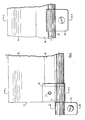
- Figure 2 is a fragmentary plan view from below of the deflector shown in Figure 1, and
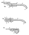
- Figures 3, 4 and 5 are cross-sectional views taken on the lines 3-3,4-4 and 5-5 respectively in Figures 1 and 2.
- Referring to Figure 1, an opening roof for a motor vehicle includes a
frame 10 bounding the aperture in the vehicle roof. Adraught deflector 12 in accordance with the invention is mounted on the fronttransverse member 14 of theframe 10. - Turning now to Figures 2 to 5, it should be understood that the deflector is symmetrical about the section line 3-3 in Figure 2 so that the components illustrated in Figures 4 and 5 have counterparts at the other end of the deflector. The
deflector 12 consists of apanel 16 and U-shapedmember 18 which is slightly shorter than thepanel 16 and has each of its ends embraced by onepart 20 of a respective end hinge. Eachhinge part 20 being connected to thepanel 16 by arespective rivet 22. Thehinge parts 20 inhibit movement of the ends of theflexible member 18 relative to thepanel 16 but the central region thereof is capable of limited relative movement, as will be explained hereinafter. - Each
hinge part 20 contains a hole for receiving a squared end of arespective hinge pin 24. A rounded end of eachhinge pin 24 is received in acorresponding hinge part 26 which in turn, is adapted to be secured to the transverse frame member 14 (Figures 1 and 5). - Referring particularly to Figures 2 and 3, the U-shaped
member 18 has a central cut-out which is bridged by ahinge pin 28 carrying ahinge part 30 which is also secured to thetransverse member 14. As can clearly be seen from Figure 2, thehinge pin 28 is not in alignment with thehinge pin 24, this being due to the above mentioned curvature of the vehicle roof. - In use, the deflector can pivot from the deployed position shown in Figure 1 to a position in which its
trailing edge 32 projects forwardly towards the windscreen adjacent to the head lining within the car. As a result of the misalignment of the pivot pins of the various hinges, the edge of thepanel 16 nearest to the hinges moves inwardly and outwardly between the limbs of the U-shapedmember 18, such movement being accbmmodated by the clearance space 34 (Figure 3). - The
hinge parts 26 of the end hinges may be formed of spring steel configured so as to grip theirrespective hinge pins 24 so as to hold thedeflector 12 in any preset position. If it is desired to make the operation of the wind deflector bistable between its deployed and non-deployed positions, parts of thepivot pins 24 may be formed with cam profiles which will engage by respective leaf springs or spring-loaded plungers.
Claims (3)
Applications Claiming Priority (2)
| Application Number | Priority Date | Filing Date | Title |
|---|---|---|---|
| GB8033103 | 1980-10-14 | ||
| GB8033103 | 1980-10-14 |
Publications (2)
| Publication Number | Publication Date |
|---|---|
| EP0049984A1 EP0049984A1 (en) | 1982-04-21 |
| EP0049984B1 true EP0049984B1 (en) | 1986-01-08 |
Family
ID=10516657
Family Applications (1)
| Application Number | Title | Priority Date | Filing Date |
|---|---|---|---|
| EP19810304588 Expired EP0049984B1 (en) | 1980-10-14 | 1981-10-05 | Draught deflector for vehicles |
Country Status (2)
| Country | Link |
|---|---|
| EP (1) | EP0049984B1 (en) |
| DE (1) | DE3173461D1 (en) |
Family Cites Families (2)
| Publication number | Priority date | Publication date | Assignee | Title |
|---|---|---|---|---|
| GB1070018A (en) * | 1963-10-16 | 1967-05-24 | Weathershields Ltd | Draught deflector for vehicles |
| GB1353150A (en) * | 1970-05-16 | 1974-05-15 | Weathershields Ltd | Hinged draught deflectors for vehicles |
-
1981
- 1981-10-05 EP EP19810304588 patent/EP0049984B1/en not_active Expired
- 1981-10-05 DE DE8181304588T patent/DE3173461D1/en not_active Expired
Also Published As
| Publication number | Publication date |
|---|---|
| EP0049984A1 (en) | 1982-04-21 |
| DE3173461D1 (en) | 1986-02-20 |
Similar Documents
| Publication | Publication Date | Title |
|---|---|---|
| US9669804B2 (en) | Connector for installing and articulating a windscreen wiper on the end of a drive arm | |
| US5632065A (en) | Extended cab pickup truck concealed cargo door hinge having a spring stop detent | |
| US5283925A (en) | Windshield wiper air deflector movable in a single plane to compensate for windshield curvature | |
| US4800624A (en) | Hinge with elastomerically supported check spring | |
| US5819361A (en) | Wiper blade for a window washing apparatus | |
| US20030131437A1 (en) | Windscreen wiper | |
| US4650241A (en) | Side door hinge mechanism in motor vehicle | |
| US4658475A (en) | Side door hinge mechanism in motor vehicle | |
| US5244247A (en) | Door installation arrangement for vehicle | |
| US4953251A (en) | Wiper joint structure | |
| US4759583A (en) | Device for releasably mounting pivotable arm rests of seats, in particular center arm rests of motor vehicle rear seats | |
| US4935983A (en) | Windshield wiper system | |
| US4947508A (en) | Wiper arm, especially for motor vehicle windshield wiper systems | |
| US5860186A (en) | Lift-controlled windscreen wiper device | |
| US6290287B1 (en) | Structural element with at least a headlamp, and method for mounting such an assembly in a motor vehicle body | |
| JPS61200025A (en) | Tilt and slide type sun roof of car | |
| US6019417A (en) | Articulated device for attaching a top storage well cover | |
| EP0049984A1 (en) | Draught deflector for vehicles | |
| KR960016478B1 (en) | Car door hinges | |
| GB1574537A (en) | Motor vehicle and wind deflector therefor | |
| EP0716963B1 (en) | Device for anchoring one end of a motor vehicle seat belt | |
| US3427676A (en) | Windshield wiper arm | |
| GB2029345A (en) | Vehicle sliding roof assembly | |
| JPH0948328A (en) | Wiper assembly for windshield of automobile | |
| US6010226A (en) | Vehicle exterior mirror |
Legal Events
| Date | Code | Title | Description |
|---|---|---|---|
| PUAI | Public reference made under article 153(3) epc to a published international application that has entered the european phase |
Free format text: ORIGINAL CODE: 0009012 |
|
| AK | Designated contracting states |
Designated state(s): DE FR GB IT NL |
|
| 17P | Request for examination filed |
Effective date: 19821012 |
|
| RAP1 | Party data changed (applicant data changed or rights of an application transferred) |
Owner name: BRISTOL STREET MOTORS (HENDON) LIMITED |
|
| RBV | Designated contracting states (corrected) |
Designated state(s): DE FR GB IT |
|
| RAP1 | Party data changed (applicant data changed or rights of an application transferred) |
Owner name: BRITAX WEATHERSHIELDS LIMITED |
|
| RAP1 | Party data changed (applicant data changed or rights of an application transferred) |
Owner name: BRITAX WEATHERSHIELDS LIMITED |
|
| ITF | It: translation for a ep patent filed | ||
| GRAA | (expected) grant |
Free format text: ORIGINAL CODE: 0009210 |
|
| AK | Designated contracting states |
Designated state(s): DE FR GB IT |
|
| ET | Fr: translation filed | ||
| REF | Corresponds to: |
Ref document number: 3173461 Country of ref document: DE Date of ref document: 19860220 |
|
| PLBE | No opposition filed within time limit |
Free format text: ORIGINAL CODE: 0009261 |
|
| STAA | Information on the status of an ep patent application or granted ep patent |
Free format text: STATUS: NO OPPOSITION FILED WITHIN TIME LIMIT |
|
| 26N | No opposition filed | ||
| PG25 | Lapsed in a contracting state [announced via postgrant information from national office to epo] |
Ref country code: GB Effective date: 19881005 |
|
| PG25 | Lapsed in a contracting state [announced via postgrant information from national office to epo] |
Ref country code: DE Effective date: 19890131 |
|
| PG25 | Lapsed in a contracting state [announced via postgrant information from national office to epo] |
Ref country code: FR Free format text: LAPSE BECAUSE OF NON-PAYMENT OF DUE FEES Effective date: 19890630 |
|
| GBPC | Gb: european patent ceased through non-payment of renewal fee | ||
| REG | Reference to a national code |
Ref country code: FR Ref legal event code: ST |