EP0049267B1 - Faultindicating circuit for an automotive alternator battery charging system - Google Patents
Faultindicating circuit for an automotive alternator battery charging system Download PDFInfo
- Publication number
- EP0049267B1 EP0049267B1 EP81901033A EP81901033A EP0049267B1 EP 0049267 B1 EP0049267 B1 EP 0049267B1 EP 81901033 A EP81901033 A EP 81901033A EP 81901033 A EP81901033 A EP 81901033A EP 0049267 B1 EP0049267 B1 EP 0049267B1
- Authority
- EP
- European Patent Office
- Prior art keywords
- alternator
- lamp
- terminal
- battery
- voltage
- Prior art date
- Legal status (The legal status is an assumption and is not a legal conclusion. Google has not performed a legal analysis and makes no representation as to the accuracy of the status listed.)
- Expired
Links
Images

Classifications
-
- G—PHYSICS
- G01—MEASURING; TESTING
- G01R—MEASURING ELECTRIC VARIABLES; MEASURING MAGNETIC VARIABLES
- G01R31/00—Arrangements for testing electric properties; Arrangements for locating electric faults; Arrangements for electrical testing characterised by what is being tested not provided for elsewhere
- G01R31/005—Testing of electric installations on transport means
- G01R31/006—Testing of electric installations on transport means on road vehicles, e.g. automobiles or trucks
-
- G—PHYSICS
- G01—MEASURING; TESTING
- G01R—MEASURING ELECTRIC VARIABLES; MEASURING MAGNETIC VARIABLES
- G01R31/00—Arrangements for testing electric properties; Arrangements for locating electric faults; Arrangements for electrical testing characterised by what is being tested not provided for elsewhere
- G01R31/34—Testing dynamo-electric machines
- G01R31/343—Testing dynamo-electric machines in operation
-
- H—ELECTRICITY
- H02—GENERATION; CONVERSION OR DISTRIBUTION OF ELECTRIC POWER
- H02J—CIRCUIT ARRANGEMENTS OR SYSTEMS FOR SUPPLYING OR DISTRIBUTING ELECTRIC POWER; SYSTEMS FOR STORING ELECTRIC ENERGY
- H02J7/00—Circuit arrangements for charging or depolarising batteries or for supplying loads from batteries
- H02J7/0029—Circuit arrangements for charging or depolarising batteries or for supplying loads from batteries with safety or protection devices or circuits
- H02J7/00302—Overcharge protection
-
- H—ELECTRICITY
- H02—GENERATION; CONVERSION OR DISTRIBUTION OF ELECTRIC POWER
- H02J—CIRCUIT ARRANGEMENTS OR SYSTEMS FOR SUPPLYING OR DISTRIBUTING ELECTRIC POWER; SYSTEMS FOR STORING ELECTRIC ENERGY
- H02J7/00—Circuit arrangements for charging or depolarising batteries or for supplying loads from batteries
- H02J7/0029—Circuit arrangements for charging or depolarising batteries or for supplying loads from batteries with safety or protection devices or circuits
- H02J7/00308—Overvoltage protection
-
- H—ELECTRICITY
- H02—GENERATION; CONVERSION OR DISTRIBUTION OF ELECTRIC POWER
- H02J—CIRCUIT ARRANGEMENTS OR SYSTEMS FOR SUPPLYING OR DISTRIBUTING ELECTRIC POWER; SYSTEMS FOR STORING ELECTRIC ENERGY
- H02J7/00—Circuit arrangements for charging or depolarising batteries or for supplying loads from batteries
- H02J7/0047—Circuit arrangements for charging or depolarising batteries or for supplying loads from batteries with monitoring or indicating devices or circuits
-
- H—ELECTRICITY
- H02—GENERATION; CONVERSION OR DISTRIBUTION OF ELECTRIC POWER
- H02J—CIRCUIT ARRANGEMENTS OR SYSTEMS FOR SUPPLYING OR DISTRIBUTING ELECTRIC POWER; SYSTEMS FOR STORING ELECTRIC ENERGY
- H02J7/00—Circuit arrangements for charging or depolarising batteries or for supplying loads from batteries
- H02J7/14—Circuit arrangements for charging or depolarising batteries or for supplying loads from batteries for charging batteries from dynamo-electric generators driven at varying speed, e.g. on vehicle
-
- Y—GENERAL TAGGING OF NEW TECHNOLOGICAL DEVELOPMENTS; GENERAL TAGGING OF CROSS-SECTIONAL TECHNOLOGIES SPANNING OVER SEVERAL SECTIONS OF THE IPC; TECHNICAL SUBJECTS COVERED BY FORMER USPC CROSS-REFERENCE ART COLLECTIONS [XRACs] AND DIGESTS
- Y10—TECHNICAL SUBJECTS COVERED BY FORMER USPC
- Y10S—TECHNICAL SUBJECTS COVERED BY FORMER USPC CROSS-REFERENCE ART COLLECTIONS [XRACs] AND DIGESTS
- Y10S320/00—Electricity: battery or capacitor charging or discharging
- Y10S320/13—Fault detection
Definitions
- the present invention relates generally to the field of indicating circuits for use in automotive alternator battery charging systems. More particularly, the present invention relates to indicating circuits which provide visual indications of the malfunctioning of an automotive alternator battery charging circuit whose output is controlled in response to sensed battery voltage by a voltage regulator.
- Voltage regulator controlled automotive alternator battery charging systems are commonly used in automotive electrical systems to provide for keeping an automotive storage battery at a full charge level. These type of systems function by a voltage regulator controlling the field coil excitation of an alternator in response to sensed battery voltage wherein the output of the alternator is full wave rectified and utilized to maintain the charge on the storage battery.
- an indicator lamp is typically used to provide an indication of 0 alternator output so as to alert the operator of the automobile to a malfunctioning of the battery charging system.
- the DC current which is utilized to provide a lower alternator output indication before rotation of the alternator rotor carrying the field coil has commenced is also utilized to supply the alternator field coil excitation.
- the prior art system which utilizes a single light to indicate both low and high alternator outputs has the disadvantage in that the operator of the automobile has no indication if the alternator malfunction is caused by an excessive alternator output or a deficient alternator output.
- an excessive alternator output prolonged operation of the charging system in this mode can readily result in damage to the battery and alternator due to over charging of the battery and the generation of extremely large alternator voltages.
- This is to be contrasted with prolonged operation of the alternator battery charging system when the alternator output is found to be deficient.
- the only danger is that the battery will eventually discharge after prolonged usage.
- the operator of the automobile is aware of which type of alternator malfunction has occurred, he may unknowingly risk damage to the alternator and battery by attempting to continue to drive the automobile while the charging system has malfunctioned.
- US-A-4000453 shows a system in which an indicating device provides different visual indications of high and low voltage faults. This indicating device is however separate from and additional to the lamp which passes initial field coil excitation current and the system suffers the same disadvantages as the above mentioned systems in which an additional indicating device is required.
- An object of the present invention is to provide an improved fault indicating circuit for an automobile alternator battery charging system which overcomes the aforementioned disadvantages a and in which high voltage detector means is provided for illuminating the lamp to provide a second visual indication in response to the sensed alternator output signal being above a second predetermined level greater than the first predetermined level whereby the fault indicating circuit utilizes a single display lamp to provide different distinct indications indicative of high and low alternator output modes of failure for an alternator battery charging system.
- an alternator battery charging system or a fault indicating circuit according to claim 1 or claim 3 respectively.
- the lamp is constantly energized to provide a continuous visual illumination indication representative of either the low or high charging voltage failure mode of the alternator, while the lamp receives periodic pulsating excitation to provide a flickering visual illumination indication indicative of the other failure mode of the alternator charging system, the lamp being de-energized for the normal alternator mode of operation.
- said sensed alternator output signal is provided by diode means which provide an auxiliary rectified alternator output corresponding in magnitude to a rectified alternator output charging signal and, wherein said auxiliary alternator output is isolated from said rectified alternator output battery charging signal. All failure modes are preferably indicated by a dashboard mounted lamp.
- the charging system 10 comprises an alternator 11 (shown dashed) which provides positive and negative rectified battery charging output voltages at terminals 12 and 13, respectively, that are directly connected to the positive and negative terminals of a storage battery 14 wherein the negative terminal of the battery is grounded.
- the output of the alternator 11 is essentially controlled by a voltage regulator 15 which effectively monitors the positive battery voltage at a terminal V 6 and provides, in accordance with the monitored voltage, control excitation to a rotatable field coil 16 of the alternator 11.
- a fault indicator circuit 17 is responsive to an auxiliary rectified output of the alternator 11 provided at a terminal 18 and provides various fault indicating excitations for a fault indicator lamp 19.
- the lamp 19 is mounted in the dashboard of a vehicle carrying the alternator charging system 10.
- the alternator 11 comprises three stationary output windings 20, 21, and 22 arranged in delta configuration having nodes 23 through 25. Each of the nodes 23 through 25 is coupled to one anode and one cathode of main alternator output positive and negative rectifying diodes 26 through 28 and 29 through 31, respectively.
- the cathodes of positive rectifying diodes 26 through 28 are directly connected together and connected to positive output alternator terminal 12, while the anodes of negative rectifying diodes 29 through 31 are connected together and directly connected to negative alternator output terminal 13 which is grounded.
- the alternator 11 also comprises the rotatable alternator field excitation coil 16 which is contemplated as being rotated by an automobile internal combustion engine drive shaft.
- the alternator 11 includes three auxiliary output rectifying diodes 32 through 34 which have their anodes coupled to terminals 23 through 25, respectively, and have their cathodes connected together at terminal 18 to provide a rectified auxiliary positive alternator output at this terminal.
- the rectified auxiliary output of the terminal 18 is directly related to the rectified charging output at the terminal 12, but is isolated electrically therefrom.
- all of the components recited above and shown within the dashed lines of the alternator 11 are mounted on or within the physical housing of the alternator 11.
- the alternator operates by receiving an excitation signal in its field coil 16 which results in inducing AC output signals in the windings 20 through 22 due to the existence of the alternator magnetic field and due to relative movement between the field created by the field coil 16 and the output windings 20 through 22.
- the field coil 16 is rotated by a drive shaft of an automobile engine while the output windings 20-23 remain stationary. This type of construction is well known and will therefore not be discussed further.
- the positive rectified output of the alternator 11 is provided at the terminal 12 and is coupled to the positive terminal of the battery 14 by a cable 35.
- the negative rectified output of the alternator 11 provided at the terminal 13 is coupled by a cable 36 to ground and to the negative terminal of the battery 14.
- the alternator field coil 16 is connected between the terminal 18 and a test terminal 37 which corresponds to the output terminal of a driver stage 38 shown dashed in Figure 1.
- the driver stage 38 comprises a Darlington NPN transistor configuration 39 having its output collector corresponding to the terminal 37, its output emitter connected to ground and its input base terminal connected to the terminal 18 through a resistor 40.
- a flyback diode 41 is connected in parallel with the field coil 16 with its anode directly connected to the terminal 37 and its cathode connected to the terminal 18. Essentially, the flyback diode prevents large reverse spikes from occurring across the field coil 16 during the cutoff of field coil excitation, and the Darlington device 39 acts as a switching device to control the field coil excitation since the Darlington device is in series with the field coil current.
- the voltage regulator 15 provides an output control voltage at a terminal 141 which is directly connected to the base of the Darlington device 39. In this manner the voltage regulator 15 controls the field excitation of the alternator and therefore controls the output of the alternator 11 since the alternator output is directly related to its field coil excitation when relative movement exists between the field coil 16 and the output windings 20 through 22.
- the voltage regulator 15 has an input terminal 42 which is directly connected to the center tap of a potentiometer 43 which has a capacitor 44 coupled in parallel with the resistive element of the potentiometer between a terminal 45 and ground.
- the terminal 45 is coupled to a terminal 46 through the series connection of a diode 47 and a resistor 48 with the anode of the diode 47 directly connected to the terminal 46.
- the terminal 46 is connected to a voltage sensing terminal V s through a diode 49 having its anode directly connected to the terminal V s , and the terminal V s is directly connected to the positive terminal of the battery 14.
- the preceding structure illustrates how the battery 14 provides a positive voltage at the terminal V s related to battery voltage which results in providing an adjustable, preset potential at the terminal 42 related to battery voltage which is utilized by the voltage regulator 15 to provide a control voltage at the terminal 141 that determines the field coil excitation for the alternator battery charging system.
- the components 43, 44, and 48 essentially form a ripple filter which minimizes variations of the input voltage provided at the terminal 42.
- the actual configuration for the voltage regulator 15 can be any type of suitable voltage regulator device and many such regulators are known some of which are illustrated in U.S. Patents 3,365,646, 3,138,751, and 3,673,588, all of which are assigned to the assignee of the present invention.
- the basic function of the regulator 15 is to control the field coil excitation such that a closed loop feedback control system is implemented wherein the field excitation is adjusted to maintain the voltage at the terminal 42 substantially constant. By adjusting the position of the center tap of the potentiometer 43, this will result in having the alternator 11 charge the battery 14 so as to effectively maintain a predetermined constant potential at the terminal V s and therefore at the positive battery terminal, in accordance with the setting of the potentiometer 43.
- the terminal 46 is also coupled to the terminal 18, at which the positive rectified alternator output voltage from the auxiliary diodes 32 through 34 is produced, by the series connection of a resistor 50 and two series connected identically noled diodes 51 and 52 with the anode of diode 51 directly connected to the resistor 50 and the cathode of the diode 52 directly connected to the terminal 46.
- the terminal 18 is also coupled to a terminal 152 through a diode 53 having its anode directly connected to the terminal 152.
- the terminal 152 is connected through the lamp 19 to a terminal 154 of an ignition switch 155 (shown dashed) which has another terminal 156 directly connected to the positive terminal of the battery 14.
- the auxiliary diodes 32 through 34 provide an auxiliary rectified positive voltage at the terminal 18, and this voltage now provides the field coil excitation current and at the same time prevents the forward biasing of the diode 53 and thereby normally extinguishes the lamp 19 since other circuits connected to the terminal 152 are intended to normally have high input impedances and therefore draw an insignificant amount of current such that the lamp 19 will not light.
- the components 50 through 52 provide a voltage sense protection circuit for the present invention.
- the components 50 through 52 providing terminal 46 with an alternative path by which the terminal 46 is connected to a positive voltage source which this time comprises the voltage at the terminal 18.
- the voltage at the terminal 18 is equal to the voltage at the terminal 12 which is substantially identical to the positive battery terminal voltage.
- the voltage at the terminal 46 is one diode drop below the positive battery terminal voltage and this ensures the non-conduction of current by the components 50 through 52.
- the voltage regulator 15 controls field excitation such that the voltages at the terminals 42, 45, and 46 are all maintained at substantially constant values.
- the fault indicating circuit 17 includes two identically poled series connected diodes 54 and 54A connected with the anode of diode 54 directly connected to terminal 18 and the cathode of diode 54A coupled to ground through the resistive element of a potentiometer 55.
- the center tap of the potentiometer 55 is coupled to an input terminal 56 which supplies a sensing signal to both a high voltage detector circuit 57 and a low voltage detector circuit 58.
- the signal at the terminal 56 is directly related to the rectified auxiliary positive voltage provided at the terminal 18 which should normally be substantially identical to the rectified alternator output charging signal provided at the terminal 12.
- the low voltage detector circuit 58 also receives a first predetermined reference voltage at a terminal V 1 and effectively compares this voltage with the voltage at the terminal 56 and provides an output which is coupled to a control terminal 59 of a driver stage 60 that produces a corresponding output that is coupled to the terminal 152.
- the high voltage detector circuit 57 receives a second predetermined reference voltage at a terminal VZ which is higher than the first predetermined voltage provided at the terminal V 1 .
- the high voltage detector circuit 57 effectively compares the voltage at the terminal V 2 with the voltage at the terminal 56 and provides an output at a terminal 61 that is coupled as an input to a flasher circuit 62 that provides a corresponding output to the terminal 59.
- the low voltage detector circuit 58 provides a high drive signal output to the terminal 59 in response to the voltage at the terminal 56 being below the voltage at the terminal V i .
- the driver stage 60 when energized by the low voltage detector circuit 58 will still permit the lamp 19 to supply field coil excitation to the coil 16, even though some lamp current will pass through resistor 64.
- the low voltage detector circuit 58 does not provide a high output signal at terminal 59.
- the high voltage detector circuit 57 receives the voltage at the terminal 56 and compares it with the voltage at the terminal V 2 . Whenever the voltage at the terminal 56 is greater than the voltage at the terminal V 2 , the high voltage detector circuit 57 provides a high voltage output at the terminal 61 which is an input to the flasher circuit 62 that essentially comprises a known flasher circuit such as a 555 flasher made by Motorola, Inc. Such flashers, upon the application of a high voltage control signal produce a periodic high and low voltage output at a presettable rate, whereas in response to a low voltage input, the flasher produces a constant low voltage output.
- the high voltage detector circuit 57 determines that the voltage at the terminal 56 is greater than the reference voltage provided at the .terminal V 2 , then the voltage at the terminal 59 will be an AC signal, at a low frequency of 4 Hertz for example, and this will result in the intermittent or flashing excitation of the lamp 19 by the driver 60.
- the fault-indicating circuit 17 has provided circuitry which utilizes the same indicator lamp 19 to indicate a low voltage alternator output by providing constant excitation to the indicator lamp 19 to provide one visual indication while indicating an over-voltage condition for the alternator output by utilizing the lamp 19 to provide a different visual indication comprising the intermittent excitation of the lamp 19, wherein the lamp 19 is contemplated as being de-energized for the normal alternator output voltage being provided at the terminal 18 since this output will result in a voltage at the terminal 56 which is between the voltages at the terminals V, and V 2 .
- the present invention has provided for the use of a single indicator lamp 19 wherein separate alternator voltage detecting circuits are utilized to provide different modes of excitation for the indicator lamp 19 so as to provide different visual indications wherein one visual indication indicates the existence of a larger than normal alternator output charging voltage, and the other visual indication indicates the existence of a lower than normal alternator output charging voltage.
- an excessively high alternator output charging voltage can result in permanent damage to the battery and alternator. This can occur because of the shorting of the Darlington device 39.
- breaking the connection between the terminal V s and the positive battery terminal will also result in a higher than normal alternator output voltage and produce a flashing of the light 19.
- connection line 35 can also result in an excessively high alternator output voltage since the voltage provided at the terminal 12 will now not be limited to the battery voltage because of the open circuit connection between the terminal 12 and the positive battery terminal. All of these modes of over-voltage malfunction of the alternator are designated by a flashing illumination of the lamp 19.
- the fault indicator circuit 17 indicates a low voltage malfunction prior to the rotation of the alternator due to the lamp 19 passing series field coil current through the diode 53.
- the terminal 18 Upon the existence of some alternator output at the terminal 18, the terminal 18 will supply the field coil current primarily, but the low voltage detector 58 can still determine when the voltage at the terminal 18 is below a predetermined minimum value so as to cause excitation of the lamp 19 in a constant manner as opposed to the flashing high voltage indication provided by the detector circuit 57.
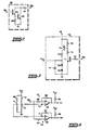
- FIG. 2 illustrates a typical embodiment for the driver circuit 60 shown in Figure 1.
- terminal 59 is connected to the base of an NPN transistor 63 having its collector connected through a resistor 64 to the terminal 152 and its emitter directly connected to the base of an NPN transistor 65 and connected to ground through a resistor 66.
- Transistor 65 has its emitter directly connected to ground and its collector directly connected to the collector of transistor 63.
- This configuration of the driver stage 60 implements a relatively low impedance at the terminal 152, as represented by the resistor 64, in the event of a positive drive signal at the terminal 59. In the absence of a positive drive signal at the terminal 59, the transistors 63 and 65 are off and the circuit does not resistively load down the terminal 152.
- FIG. 3 illustrates a configuration for a power supply circuit 70 which is contemplated as being contained in the fault indicating circuit 17.
- the power supply circuit comprises an NPN transistor 71 which has its base coupled through a resistor 72 to the terminal 152.
- Transistor 71 has its emitter directly connected to ground and its collector connected to the base of a PNP transistor 73 through a resistor 74.
- Transistor 73 has its emitter directly connected to the terminal 46, its base coupled through a resistor 75 to the terminal 46 and its collector connected through a resistor 76 to a terminal V cc which is coupled to ground through a capacitor 77.
- the terminal V cc is coupled to the-cathode of a Zener diode 78 which has its anode coupled to the anode of a diode 79 that has its cathode directly connected to ground.
- the function of the power supply 70 is essentially to provide a regulated voltage at the terminal V cc determined primarily by the magnitude of the breakdown voltage of Zener diode 78 in response to closing of the ignition switch 155 which will provide a positive voltage at the terminal 152. This is accomplished by the positive voltage at terminal 152 turning on the transistor 71 and resulting in the voltage at the terminal 46 being passed through the resistor 76 to the Zener diode 78. It is contemplated that the voltage V cc is approximately six volts whereas the terminal 46 will typically be over ten volts since it is only one diode drop below the battery voltage under normal operating conditions and normal battery voltage exceeds ten volts.
- the power supply circuit does not load down the terminal 152 since its connection to this terminal is through the base circuit of the transistor 71.
- the function of the power supply circuit 70 is to provide the stable reference voltage V cc which is utilized by the low and high voltage detector circuits 57 and 58.
- FIG. 4 illustrates a typical embodiment for the high voltage detector circuit 57 and the low voltage detector circuit 58.
- Resistor dividers 80 and 81 are coupled between the regulated voltage V cc and ground to provide the reference voltages V 1 and V 2 , respectively, at the divider midpoints, as inputs to voltage comparators 82 and 83 which receive other voltage inputs by virtue of resistors 84 and 85 that are coupled between the terminal 56 and the comparators 82 and 83, respectively.
- Input to output connected feedback resistors 87 and 88 provided for the comparators 82 and 83, respectively, such that the comparators 82 and 83 will have a slight amount of hysteresis for their switching thresholds so as to prevent false switching due to noise impulses.
- the outputs of the comparators 82 and 83 are coupled through resistors 89 and 90, respectively, to the terminal V cc , and are coupled to the terminals 59 and 61, respectively.
- the present invention provides for a detection of an open field current circuit by providing a continuous excitation signal for the lamp 19.
- Prior fault indicating circuits did not generally provide such an indication because if the field current circuit was open energizing current could not pass through the lamp 19.
- the present fault indicating circuit 17 utilizes the low voltage detector 58 to ensure that the lamp 19 is excited for an alternator output being provided at the terminal 18 when this is due to an open field current circuit. This occurs even though current through the lamp 19 is utilized to provide the initial field coil excitation current.
- the present invention also provides for detecting the shorting of the Darlington device 39, the opening of the cable 35, or the breaking of the connection between the terminal V s and the positive battery terminal, and all these faults are indicated by a flashing of the lamp 19 since these faults result in increasing the rectified alternator output voltage at the terminal 18 above a predetermined maximum value.
- the present fault indicating circuit 17 will provide a low voltage indication when the alternator output capacity is diminished to such an extent that it cannot sustain voltages between the terminals 12 and 13 to prevent typical low resistance loads across the battery 14 from lowering the battery voltage below a desited minimum level.
- An additional advantage of the present invention is that it allows determination of whether the alternator, the regulator, or the connections between these elements in the battery are defective.
- the present invention serves a diagnostic function for repairing a defective charging system and this is accomplished in the following manner.
- the repair procedure is to ground the terminal 37 to determine if the alternator or regulator is at fault. If the grounding of the terminal 37 will initially extinguish the lamp and then the lamp begins to flash, this indicates that the regulator containing the voltage regulator 15 and drive circuit 38 is faulty since the repair procedure has now ensured that excessive field coil excitation current will be drawn by shorting the terminal 37 to ground. If shorting the terminal 37 to ground does not extinguish the lamp 19, this indicates a defective alternator in that either the alternator field coil is open or other alternator problems such as open or shorted rectifying diodes or stator windings exist. This would then indicate that replacement of the alternator, which preferably includes all of the elements within the box 11, would be warranted.
- the regulator as a chassis separate from the alternator, would include at least the voltage regulator 15, the components 43-48, and drive circuit 38, and could also include the basic electronics of the fault indicating circuit 17.
- this circuitry in its entirety would be replaced after ensuring that improper cable connections have not caused the charging system fault and when the fault does not lie within the alternator chassis.
- One such modification is to add another flasher between the low voltage detector and terminal 59 to indicate low voltage by flashing the lamp at a different rate than the flasher 62.
Landscapes
- Engineering & Computer Science (AREA)
- Power Engineering (AREA)
- Physics & Mathematics (AREA)
- General Physics & Mathematics (AREA)
- Chemical & Material Sciences (AREA)
- Combustion & Propulsion (AREA)
- Control Of Charge By Means Of Generators (AREA)
- Control Of Eletrric Generators (AREA)
Abstract
Description
- The present invention relates generally to the field of indicating circuits for use in automotive alternator battery charging systems. More particularly, the present invention relates to indicating circuits which provide visual indications of the malfunctioning of an automotive alternator battery charging circuit whose output is controlled in response to sensed battery voltage by a voltage regulator.
- Voltage regulator controlled automotive alternator battery charging systems are commonly used in automotive electrical systems to provide for keeping an automotive storage battery at a full charge level. These type of systems function by a voltage regulator controlling the field coil excitation of an alternator in response to sensed battery voltage wherein the output of the alternator is full wave rectified and utilized to maintain the charge on the storage battery. In such systems, an indicator lamp is typically used to provide an indication of 0 alternator output so as to alert the operator of the automobile to a malfunctioning of the battery charging system. In some of these systems, the DC current which is utilized to provide a lower alternator output indication before rotation of the alternator rotor carrying the field coil has commenced is also utilized to supply the alternator field coil excitation.
- Both US-A-3365646 and US-A-3138751 show a fault indicating circuit for an automotive alternator battery charging system, comprising:
- a lamp, means for coupling the lamp and a field coil of the alternator such that initial battery supplied excitation current for the field coil causes illumination of the lamp by passing at least some field current through the lamp;
- and low voltage detector means for illuminating the lamp to provide a first visual indication in response to a sensed alternator output signal being below a first predetermined voltage level, even if the alternator field coil is open circuited and draws zero current.
- In these prior systems, the use of the lamp excitation current to also supply the initial field coil excitation minimizes the number of electrical connections necessary for the battery charging system. However, typically these type of charging systems only provide a visual indication of alternator malfunction in response to a low alternator charging output signal.
- Some prior art systems have recognized the need for providing a visual indication of an excessively high alternator output voltage which is therefore indicative of a malfunction of the alternator battery charging system. US-A-3673588 is an example of one of these systems in which separate sensing circuits are utilized to separately excite different lamps so as to indicate both high and low voltage conditions. In addition EP-A1-0018836 (state of the art according to Art. 54(3) EPC) contemplates the use of a simple lamp for providing a single visual display indicative of either low or high alternate voltage output conditions. This lamp is also used to provide the initial field with excitation current.
- In the prior systems which utilize a plurality of indicating lights, this requires an additional indicator light be provided on the dashboard of aa automobile and the provision of this additional lamp is generally considered to be undesirable for aesthetic reasons as well as since additional complex circuitry may have to be utilized for providing the proper excitation to the over voltage light as well as for providing a mechanism for testing the over voltage light to ensure that it is in operating order. Thus circuitry must exist to insure (test) that this light is not burned out, since typically the light would only come on during a high voltage failure mode.
- The prior art system which utilizes a single light to indicate both low and high alternator outputs has the disadvantage in that the operator of the automobile has no indication if the alternator malfunction is caused by an excessive alternator output or a deficient alternator output. In the case of an excessive alternator output, prolonged operation of the charging system in this mode can readily result in damage to the battery and alternator due to over charging of the battery and the generation of extremely large alternator voltages. This is to be contrasted with prolonged operation of the alternator battery charging system when the alternator output is found to be deficient. In this latter mode, the only danger is that the battery will eventually discharge after prolonged usage. Thus, unless the operator of the automobile is aware of which type of alternator malfunction has occurred, he may unknowingly risk damage to the alternator and battery by attempting to continue to drive the automobile while the charging system has malfunctioned.
- US-A-4000453 shows a system in which an indicating device provides different visual indications of high and low voltage faults. This indicating device is however separate from and additional to the lamp which passes initial field coil excitation current and the system suffers the same disadvantages as the above mentioned systems in which an additional indicating device is required.
- Some prior systems have illustrated separate plug in test modules in which high and low alternator output failure modes are indicated by a flashing test light, separate from the dashboard mounted lamp which supplies initial field excitation, while other failure modes are indicated by continuous illumination of the test light. These systems require disconnection of the dashboard lamp, and fail to differentiate between high and low output failures.
- An object of the present invention is to provide an improved fault indicating circuit for an automobile alternator battery charging system which overcomes the aforementioned disadvantages a and in which high voltage detector means is provided for illuminating the lamp to provide a second visual indication in response to the sensed alternator output signal being above a second predetermined level greater than the first predetermined level whereby the fault indicating circuit utilizes a single display lamp to provide different distinct indications indicative of high and low alternator output modes of failure for an alternator battery charging system.
- This object is achieved by an alternator battery charging system or a fault indicating circuit according to claim 1 or claim 3 respectively. Preferably, the lamp is constantly energized to provide a continuous visual illumination indication representative of either the low or high charging voltage failure mode of the alternator, while the lamp receives periodic pulsating excitation to provide a flickering visual illumination indication indicative of the other failure mode of the alternator charging system, the lamp being de-energized for the normal alternator mode of operation. Also, preferably, said sensed alternator output signal is provided by diode means which provide an auxiliary rectified alternator output corresponding in magnitude to a rectified alternator output charging signal and, wherein said auxiliary alternator output is isolated from said rectified alternator output battery charging signal. All failure modes are preferably indicated by a dashboard mounted lamp.
- For a more complete understanding of the present invention reference should be made to the drawings, in which:
- Figure 1 is a combination block and schematic diagram of an automotive alternator battery charging system;
- Figure 2 is a detailed schematic of a driver stage in the charging system shown in Figure 1;
- Figure 3 is a detailed schematic of a power supply circuit shown in the charging system in Figure 1; and
- Figure 4 is a detailed schematic diagram of high and low voltage detector circuits illustrated in the charging system in Figure 1.
- Referring to Figure 1, an automotive alternator
battery charging system 10 is illustrated. Basically, thecharging system 10 comprises an alternator 11 (shown dashed) which provides positive and negative rectified battery charging output voltages atterminals 12 and 13, respectively, that are directly connected to the positive and negative terminals of astorage battery 14 wherein the negative terminal of the battery is grounded. The output of the alternator 11 is essentially controlled by avoltage regulator 15 which effectively monitors the positive battery voltage at a terminal V6 and provides, in accordance with the monitored voltage, control excitation to arotatable field coil 16 of the alternator 11. Afault indicator circuit 17 is responsive to an auxiliary rectified output of the alternator 11 provided at a terminal 18 and provides various fault indicating excitations for afault indicator lamp 19. Preferably thelamp 19 is mounted in the dashboard of a vehicle carrying thealternator charging system 10. The preceding statements generally indicate the functioning of thecharging system 10, and the details of this system will now be discussed. - The alternator 11 comprises three
stationary output windings configuration having nodes 23 through 25. Each of thenodes 23 through 25 is coupled to one anode and one cathode of main alternator output positive and negative rectifyingdiodes 26 through 28 and 29 through 31, respectively. The cathodes of positive rectifyingdiodes 26 through 28 are directly connected together and connected to positive output alternator terminal 12, while the anodes of negative rectifyingdiodes 29 through 31 are connected together and directly connected to negativealternator output terminal 13 which is grounded. The alternator 11 also comprises the rotatable alternatorfield excitation coil 16 which is contemplated as being rotated by an automobile internal combustion engine drive shaft. In addition the alternator 11 includes three auxiliary output rectifyingdiodes 32 through 34 which have their anodes coupled toterminals 23 through 25, respectively, and have their cathodes connected together at terminal 18 to provide a rectified auxiliary positive alternator output at this terminal. The rectified auxiliary output of the terminal 18 is directly related to the rectified charging output at the terminal 12, but is isolated electrically therefrom. Preferably, all of the components recited above and shown within the dashed lines of the alternator 11 are mounted on or within the physical housing of the alternator 11. - Essentially, the alternator operates by receiving an excitation signal in its
field coil 16 which results in inducing AC output signals in thewindings 20 through 22 due to the existence of the alternator magnetic field and due to relative movement between the field created by thefield coil 16 and theoutput windings 20 through 22. Preferably, thefield coil 16 is rotated by a drive shaft of an automobile engine while the output windings 20-23 remain stationary. This type of construction is well known and will therefore not be discussed further. - The positive rectified output of the alternator 11 is provided at the terminal 12 and is coupled to the positive terminal of the
battery 14 by acable 35. Similarly, the negative rectified output of the alternator 11 provided at theterminal 13 is coupled by a cable 36 to ground and to the negative terminal of thebattery 14. Thealternator field coil 16 is connected between the terminal 18 and atest terminal 37 which corresponds to the output terminal of adriver stage 38 shown dashed in Figure 1. Thedriver stage 38 comprises a DarlingtonNPN transistor configuration 39 having its output collector corresponding to theterminal 37, its output emitter connected to ground and its input base terminal connected to the terminal 18 through aresistor 40. Aflyback diode 41 is connected in parallel with thefield coil 16 with its anode directly connected to theterminal 37 and its cathode connected to the terminal 18. Essentially, the flyback diode prevents large reverse spikes from occurring across thefield coil 16 during the cutoff of field coil excitation, and the Darlingtondevice 39 acts as a switching device to control the field coil excitation since the Darlington device is in series with the field coil current. - The
voltage regulator 15 provides an output control voltage at a terminal 141 which is directly connected to the base of the Darlingtondevice 39. In this manner thevoltage regulator 15 controls the field excitation of the alternator and therefore controls the output of the alternator 11 since the alternator output is directly related to its field coil excitation when relative movement exists between thefield coil 16 and theoutput windings 20 through 22. - The
voltage regulator 15 has aninput terminal 42 which is directly connected to the center tap of apotentiometer 43 which has a capacitor 44 coupled in parallel with the resistive element of the potentiometer between a terminal 45 and ground. The terminal 45 is coupled to a terminal 46 through the series connection of adiode 47 and aresistor 48 with the anode of thediode 47 directly connected to the terminal 46. The terminal 46 is connected to a voltage sensing terminal Vs through adiode 49 having its anode directly connected to the terminal Vs, and the terminal Vs is directly connected to the positive terminal of thebattery 14. The preceding structure illustrates how thebattery 14 provides a positive voltage at the terminal Vs related to battery voltage which results in providing an adjustable, preset potential at the terminal 42 related to battery voltage which is utilized by thevoltage regulator 15 to provide a control voltage at the terminal 141 that determines the field coil excitation for the alternator battery charging system. Thecomponents - The actual configuration for the
voltage regulator 15 can be any type of suitable voltage regulator device and many such regulators are known some of which are illustrated in U.S. Patents 3,365,646, 3,138,751, and 3,673,588, all of which are assigned to the assignee of the present invention. The basic function of theregulator 15 is to control the field coil excitation such that a closed loop feedback control system is implemented wherein the field excitation is adjusted to maintain the voltage at the terminal 42 substantially constant. By adjusting the position of the center tap of thepotentiometer 43, this will result in having the alternator 11 charge thebattery 14 so as to effectively maintain a predetermined constant potential at the terminal Vs and therefore at the positive battery terminal, in accordance with the setting of thepotentiometer 43. - The terminal 46 is also coupled to the terminal 18, at which the positive rectified alternator output voltage from the
auxiliary diodes 32 through 34 is produced, by the series connection of aresistor 50 and two series connected identically noled diodes 51 and 52 with the anode of diode 51 directly connected to theresistor 50 and the cathode of the diode 52 directly connected to the terminal 46. The terminal 18 is also coupled to a terminal 152 through adiode 53 having its anode directly connected to the terminal 152. The terminal 152 is connected through thelamp 19 to aterminal 154 of an ignition switch 155 (shown dashed) which has another terminal 156 directly connected to the positive terminal of thebattery 14. - The above-recited connections allow the
charging system 10 to function as follows. When theignition switch 155 is closed during initial startup of the automobile engine before any substantial output is produced by the alternator 11, field coil excitation is provided by the series current which passes throught thelamp 19, thediode 53 and thefield coil 16. This is because the positive battery voltage passed through thelamp 19 will forward bias thediode 53 and supply a positive voltage at the terminal 18 that results in turning on theDarlington device 39, by virtue of the bias applied to the base of this device through theresistor 40, and this results in providing field current to thefield coil 16. Thevoltage regulator 15 allows the turning on of theDarlington device 39 since, during start up, the battery voltage falls below the voltage level at which theregulator 15 andpotentiometer 43 are set to maintain. After the alternator has started rotating, theauxiliary diodes 32 through 34 provide an auxiliary rectified positive voltage at the terminal 18, and this voltage now provides the field coil excitation current and at the same time prevents the forward biasing of thediode 53 and thereby normally extinguishes thelamp 19 since other circuits connected to the terminal 152 are intended to normally have high input impedances and therefore draw an insignificant amount of current such that thelamp 19 will not light. - The
components 50 through 52 provide a voltage sense protection circuit for the present invention. In some prior art systems, if the connection between the voltage sensing terminal Vs and the battery is disconnected, this will result in creating an extremely low voltage, or 0 voltage, at the regulator input terminal corresponding to the terminal 42. The voltage regulator would then misinterpret this as an extremely low battery voltage and provide maximum field coil excitation resulting in damage to the battery due to overcharging. This is prevented in thepresent charging system 10 by thecomponents 50 through 52 providingterminal 46 with an alternative path by which the terminal 46 is connected to a positive voltage source which this time comprises the voltage at the terminal 18. - During the normal operation of the alternator 11, the voltage at the terminal 18 is equal to the voltage at the terminal 12 which is substantially identical to the positive battery terminal voltage. During this condition, the voltage at the terminal 46 is one diode drop below the positive battery terminal voltage and this ensures the non-conduction of current by the
components 50 through 52. However, if the terminal Vs is disconnected from the positive battery terminal, then thecomponents 50 through 52 conduct and the voltage at the terminal 46 will be more than two diode drops below the voltage at the terminal 18. In the closed loopalternator charging system 10, thevoltage regulator 15 controls field excitation such that the voltages at theterminals regulator 15 will maintain the same voltage at the terminal 46 and this will result in raising the voltage at the terminal 18, not to an uncontrolled high voltage, but to a slightly higher voltage determined by one additional diode drop and the series voltage drop across theresistor 50. This ensures that excessively large battery charging voltages are not produced across theterminals 12 and 13 due to the disconnection of the terminal Vs from the positive battery terminal, and that only a moderate increase in the charging voltage is provided in such a case. This feature has been provided in some prior art charging systems, and is especially significant in conjunction with thefault indicating circuit 17 and will be discussed subsequently. - The
fault indicating circuit 17 includes two identically poled series connecteddiodes 54 and 54A connected with the anode ofdiode 54 directly connected to terminal 18 and the cathode of diode 54A coupled to ground through the resistive element of apotentiometer 55. The center tap of thepotentiometer 55 is coupled to aninput terminal 56 which supplies a sensing signal to both a highvoltage detector circuit 57 and a lowvoltage detector circuit 58. The signal at the terminal 56 is directly related to the rectified auxiliary positive voltage provided at the terminal 18 which should normally be substantially identical to the rectified alternator output charging signal provided at the terminal 12. - The low
voltage detector circuit 58 also receives a first predetermined reference voltage at a terminal V1 and effectively compares this voltage with the voltage at the terminal 56 and provides an output which is coupled to acontrol terminal 59 of a driver stage 60 that produces a corresponding output that is coupled to the terminal 152. The highvoltage detector circuit 57 receives a second predetermined reference voltage at a terminal VZ which is higher than the first predetermined voltage provided at the terminal V1. The highvoltage detector circuit 57 effectively compares the voltage at the terminal V2 with the voltage at the terminal 56 and provides an output at a terminal 61 that is coupled as an input to aflasher circuit 62 that provides a corresponding output to the terminal 59. - Essentially, the low
voltage detector circuit 58 provides a high drive signal output to the terminal 59 in response to the voltage at the terminal 56 being below the voltage at the terminal Vi. This results in the driver stage 60 providing a relatively low impedance connection to ground at the terminal 152 which in turn results in energizing thelamp 19 and keeping this lamp energized as long as this low voltage condition for the voltage at the terminal 56 exists. The driver stage 60, when energized by the lowvoltage detector circuit 58 will still permit thelamp 19 to supply field coil excitation to thecoil 16, even though some lamp current will pass throughresistor 64. When the voltage atterminal 56 is above V↑ , the lowvoltage detector circuit 58 does not provide a high output signal atterminal 59. - The high
voltage detector circuit 57 receives the voltage at the terminal 56 and compares it with the voltage at the terminal V2. Whenever the voltage at the terminal 56 is greater than the voltage at the terminal V2, the highvoltage detector circuit 57 provides a high voltage output at the terminal 61 which is an input to theflasher circuit 62 that essentially comprises a known flasher circuit such as a 555 flasher made by Motorola, Inc. Such flashers, upon the application of a high voltage control signal produce a periodic high and low voltage output at a presettable rate, whereas in response to a low voltage input, the flasher produces a constant low voltage output. Thus, if the highvoltage detector circuit 57 determines that the voltage at the terminal 56 is greater than the reference voltage provided at the .terminal V2, then the voltage at the terminal 59 will be an AC signal, at a low frequency of 4 Hertz for example, and this will result in the intermittent or flashing excitation of thelamp 19 by the driver 60. - If the voltage at the terminal 56 is greater than the voltage at the terminal V" but less than the voltage at the terminal V2, then neither the
low voltage detector 58 nor thehigh voltage detector 57 will result in providing a signal at the terminal 152 to cause thelamp 19 to be turned on, and the lamp will be de-energized (non-illuminated). - Thus, the fault-indicating
circuit 17 has provided circuitry which utilizes thesame indicator lamp 19 to indicate a low voltage alternator output by providing constant excitation to theindicator lamp 19 to provide one visual indication while indicating an over-voltage condition for the alternator output by utilizing thelamp 19 to provide a different visual indication comprising the intermittent excitation of thelamp 19, wherein thelamp 19 is contemplated as being de-energized for the normal alternator output voltage being provided at the terminal 18 since this output will result in a voltage at the terminal 56 which is between the voltages at the terminals V, and V2. - It should be noted that in the case of the disconnection of the voltage sensing terminal Vs from the positive battery terminal, it is contemplated that the voltage at the terminal 18 will rise due to the action of the
components 50 to 52 such that the voltage at the terminal 56 will now exceed the voltage at the terminal V2 and an indication of over-voltage will be provided by the flashing of thelamp 19. This creates a visual warning indication between the breaking of the connection between the positive battery terminal and the terminal Vs, while still regulating the alternator output to a safe but higher than normal level. - By the above-recited structure, it is apparent that the present invention has provided for the use of a
single indicator lamp 19 wherein separate alternator voltage detecting circuits are utilized to provide different modes of excitation for theindicator lamp 19 so as to provide different visual indications wherein one visual indication indicates the existence of a larger than normal alternator output charging voltage, and the other visual indication indicates the existence of a lower than normal alternator output charging voltage. As was previously noted, an excessively high alternator output charging voltage can result in permanent damage to the battery and alternator. This can occur because of the shorting of theDarlington device 39. As was also previously noted, breaking the connection between the terminal Vs and the positive battery terminal will also result in a higher than normal alternator output voltage and produce a flashing of the light 19. In addition, a break in theconnection line 35 can also result in an excessively high alternator output voltage since the voltage provided at the terminal 12 will now not be limited to the battery voltage because of the open circuit connection between the terminal 12 and the positive battery terminal. All of these modes of over-voltage malfunction of the alternator are designated by a flashing illumination of thelamp 19. - The
fault indicator circuit 17 indicates a low voltage malfunction prior to the rotation of the alternator due to thelamp 19 passing series field coil current through thediode 53. Upon the existence of some alternator output at the terminal 18, the terminal 18 will supply the field coil current primarily, but thelow voltage detector 58 can still determine when the voltage at the terminal 18 is below a predetermined minimum value so as to cause excitation of thelamp 19 in a constant manner as opposed to the flashing high voltage indication provided by thedetector circuit 57. - Figure 2 illustrates a typical embodiment for the driver circuit 60 shown in Figure 1. In Figure 2, as well as Figures 3 and 4, identically corresponding components have been identically numbered. In Figure 2,
terminal 59 is connected to the base of anNPN transistor 63 having its collector connected through aresistor 64 to the terminal 152 and its emitter directly connected to the base of anNPN transistor 65 and connected to ground through a resistor 66.Transistor 65 has its emitter directly connected to ground and its collector directly connected to the collector oftransistor 63. This configuration of the driver stage 60 implements a relatively low impedance at the terminal 152, as represented by theresistor 64, in the event of a positive drive signal at the terminal 59. In the absence of a positive drive signal at the terminal 59, thetransistors terminal 152. - Figure 3 illustrates a configuration for a
power supply circuit 70 which is contemplated as being contained in thefault indicating circuit 17. The power supply circuit comprises anNPN transistor 71 which has its base coupled through a resistor 72 to the terminal 152.Transistor 71 has its emitter directly connected to ground and its collector connected to the base of aPNP transistor 73 through aresistor 74.Transistor 73 has its emitter directly connected to the terminal 46, its base coupled through aresistor 75 to the terminal 46 and its collector connected through a resistor 76 to a terminal Vcc which is coupled to ground through acapacitor 77. The terminal Vcc is coupled to the-cathode of aZener diode 78 which has its anode coupled to the anode of a diode 79 that has its cathode directly connected to ground. - The function of the
power supply 70 is essentially to provide a regulated voltage at the terminal Vcc determined primarily by the magnitude of the breakdown voltage ofZener diode 78 in response to closing of theignition switch 155 which will provide a positive voltage at the terminal 152. This is accomplished by the positive voltage atterminal 152 turning on thetransistor 71 and resulting in the voltage at the terminal 46 being passed through the resistor 76 to theZener diode 78. It is contemplated that the voltage Vcc is approximately six volts whereas the terminal 46 will typically be over ten volts since it is only one diode drop below the battery voltage under normal operating conditions and normal battery voltage exceeds ten volts. It should be noted that the power supply circuit does not load down the terminal 152 since its connection to this terminal is through the base circuit of thetransistor 71. The function of thepower supply circuit 70 is to provide the stable reference voltage Vcc which is utilized by the low and highvoltage detector circuits - Figure 4 illustrates a typical embodiment for the high
voltage detector circuit 57 and the lowvoltage detector circuit 58.Resistor dividers voltage comparators resistors comparators feedback resistors comparators comparators comparators resistors 89 and 90, respectively, to the terminal Vcc, and are coupled to theterminals - With regard to the charging
system 10, the following system operations are considered significant. - It should be noted that the present invention provides for a detection of an open field current circuit by providing a continuous excitation signal for the
lamp 19. Prior fault indicating circuits did not generally provide such an indication because if the field current circuit was open energizing current could not pass through thelamp 19. However, the presentfault indicating circuit 17 utilizes thelow voltage detector 58 to ensure that thelamp 19 is excited for an alternator output being provided at the terminal 18 when this is due to an open field current circuit. This occurs even though current through thelamp 19 is utilized to provide the initial field coil excitation current. - The present invention also provides for detecting the shorting of the
Darlington device 39, the opening of thecable 35, or the breaking of the connection between the terminal Vs and the positive battery terminal, and all these faults are indicated by a flashing of thelamp 19 since these faults result in increasing the rectified alternator output voltage at the terminal 18 above a predetermined maximum value. In addition, the presentfault indicating circuit 17 will provide a low voltage indication when the alternator output capacity is diminished to such an extent that it cannot sustain voltages between theterminals 12 and 13 to prevent typical low resistance loads across thebattery 14 from lowering the battery voltage below a desited minimum level. - An additional advantage of the present invention is that it allows determination of whether the alternator, the regulator, or the connections between these elements in the battery are defective. Thus, the present invention serves a diagnostic function for repairing a defective charging system and this is accomplished in the following manner.
- If the
lamp 19 flashes, this can be due to the opening of theconnection line 35 or the opening of the connection between the terminal Vs and the positive battery terminal. Thus by making sure that thecable connection 35 and the connection between the terminal Vs and the positive battery terminal are proper, a repairman for the charging system can be sure that if thelamp 19 still flashes, then the malfunction of the charging system is due to a shorted output in theregulator 15 ordriver stage 38 resulting in continuously providing field coil excitation to the alternator resulting in an excessively high alternator output at the terminals 12 and 18. This indicates that replacing the voltage regulator module, which would typically include thedriver stage 38 as well as theregulator 15 and components 43-48, is required. - If low alternator output voltage has been indicated by the
lamp 19, the repair procedure is to ground the terminal 37 to determine if the alternator or regulator is at fault. If the grounding of the terminal 37 will initially extinguish the lamp and then the lamp begins to flash, this indicates that the regulator containing thevoltage regulator 15 and drivecircuit 38 is faulty since the repair procedure has now ensured that excessive field coil excitation current will be drawn by shorting the terminal 37 to ground. If shorting the terminal 37 to ground does not extinguish thelamp 19, this indicates a defective alternator in that either the alternator field coil is open or other alternator problems such as open or shorted rectifying diodes or stator windings exist. This would then indicate that replacement of the alternator, which preferably includes all of the elements within the box 11, would be warranted. - It is contemplated that the regulator, as a chassis separate from the alternator, would include at least the
voltage regulator 15, the components 43-48, and drivecircuit 38, and could also include the basic electronics of thefault indicating circuit 17. Thus when a regulator defect is detected this circuitry in its entirety would be replaced after ensuring that improper cable connections have not caused the charging system fault and when the fault does not lie within the alternator chassis. - While we have shown and described specific embodiments of this invention, further modifications and improvements will occur to those skilled in the art. One such modification is to add another flasher between the low voltage detector and terminal 59 to indicate low voltage by flashing the lamp at a different rate than the
flasher 62.
Claims (8)
Applications Claiming Priority (2)
| Application Number | Priority Date | Filing Date | Title |
|---|---|---|---|
| US06/137,332 US4316134A (en) | 1980-04-04 | 1980-04-04 | Fault indicating circuit for an automotive alternator battery charging system |
| US137332 | 1993-10-18 |
Publications (3)
| Publication Number | Publication Date |
|---|---|
| EP0049267A1 EP0049267A1 (en) | 1982-04-14 |
| EP0049267A4 EP0049267A4 (en) | 1982-07-26 |
| EP0049267B1 true EP0049267B1 (en) | 1985-05-02 |
Family
ID=22476910
Family Applications (1)
| Application Number | Title | Priority Date | Filing Date |
|---|---|---|---|
| EP81901033A Expired EP0049267B1 (en) | 1980-04-04 | 1981-02-19 | Faultindicating circuit for an automotive alternator battery charging system |
Country Status (7)
| Country | Link |
|---|---|
| US (1) | US4316134A (en) |
| EP (1) | EP0049267B1 (en) |
| JP (1) | JPS57500405A (en) |
| CA (1) | CA1159902A (en) |
| MX (1) | MX149384A (en) |
| WO (1) | WO1981002956A1 (en) |
| ZA (1) | ZA811339B (en) |
Families Citing this family (52)
| Publication number | Priority date | Publication date | Assignee | Title |
|---|---|---|---|---|
| JPS5722334A (en) * | 1980-07-11 | 1982-02-05 | Nippon Denso Co | Automotive voltage regulator |
| EP0051722B1 (en) * | 1980-11-08 | 1984-12-19 | Robert Bosch Gmbh | Battery charging system, especially for motor vehicles |
| IT1130536B (en) * | 1980-11-26 | 1986-06-18 | Marelli Autronica | CIRCUIT FOR THE DETECTION AND SIGNALING OF FAULTS AND OPERATING ANOMALIES IN A RECHARGE SYSTEM FOR ELECTRIC ACCUMULATORS |
| US4451774A (en) * | 1981-03-06 | 1984-05-29 | Nippondenso Co., Ltd. | Vehicle mounted voltage regulator |
| US4471288A (en) * | 1982-03-23 | 1984-09-11 | Mitsubishi Denki Kabushiki Kaisha | Apparatus for controlling charging generators |
| JPS58163234A (en) * | 1982-03-23 | 1983-09-28 | 三菱電機株式会社 | Charge indicator |
| JPS58163238A (en) * | 1982-03-23 | 1983-09-28 | 三菱電機株式会社 | Controller for charging generator |
| US4549128A (en) * | 1982-11-09 | 1985-10-22 | Mitsubishi Denki Kabushiki Kaisha | Charging generator controlling device |
| JPS6077656A (en) * | 1983-10-03 | 1985-05-02 | Mitsubishi Electric Corp | Defect indicating method of dc generator for vehicle |
| JPH0710149B2 (en) * | 1984-02-20 | 1995-02-01 | 日本電装株式会社 | Vehicle charge control device |
| US4623833A (en) * | 1984-12-31 | 1986-11-18 | Motorola, Inc. | Alternator system multifunction fault detector |
| US4613808A (en) * | 1985-02-11 | 1986-09-23 | Motorola, Inc. | Fault detector for an alternator |
| DE4042519C2 (en) * | 1989-02-22 | 2000-11-09 | Motorola Inc | Diagnostic fault test system and circuit |
| DE4004427C2 (en) * | 1989-02-22 | 1995-02-09 | Motorola Inc | Diagnostic fault reporting system |
| US4932246A (en) * | 1989-02-22 | 1990-06-12 | Motorola, Inc. | Diagnostic fault test system and circuit |
| FR2649797B1 (en) * | 1989-07-11 | 1991-10-31 | Valeo Equip Electr Moteur | CIRCUIT FOR DETECTING THE ALTERNATOR-PHASE POLYPHASE CONTROL SIGNAL OF A MOTOR VEHICLE BATTERY CHARGE REGULATOR AND THE USE THEREOF |
| IT1240145B (en) * | 1990-03-22 | 1993-11-27 | Marelli Autronica | CHARGING SYSTEM OF THE BATTERY OF A MOTOR VEHICLE |
| FR2669784A1 (en) * | 1990-11-27 | 1992-05-29 | Valeo Equip Electr Moteur | DEVICE FOR REGULATING THE CHARGING VOLTAGE OF A BATTERY DELIVERED BY AN ALTERNATOR. |
| JPH04102783U (en) * | 1991-02-15 | 1992-09-04 | 日東工器株式会社 | DC battery driven hand tool |
| FR2675644B1 (en) * | 1991-04-19 | 1993-08-27 | Valeo Equip Electr Moteur | TWO-VOLTAGE ELECTRICAL CIRCUIT WITH IMPROVED FAULT SIGNALING, PARTICULARLY FOR MOTOR VEHICLE. |
| US5257190A (en) * | 1991-08-12 | 1993-10-26 | Crane Harold E | Interactive dynamic realtime management system for powered vehicles |
| JP3133850B2 (en) * | 1993-02-04 | 2001-02-13 | 三菱電機株式会社 | Control method and control device for vehicle alternator |
| DE4327484A1 (en) * | 1993-08-16 | 1995-02-23 | Bosch Gmbh Robert | Battery charger with error detection |
| JP3140270B2 (en) * | 1993-08-30 | 2001-03-05 | 株式会社日立製作所 | Power generation voltage regulator for automobile |
| JP3299380B2 (en) * | 1994-04-27 | 2002-07-08 | 三菱電機株式会社 | Control device for vehicle alternator |
| JP3508363B2 (en) * | 1995-05-11 | 2004-03-22 | 株式会社デンソー | Power supply system for vehicles |
| US5982050A (en) * | 1996-03-14 | 1999-11-09 | Fuji Jukogyo Kabushiki Kaisha | Power supply unit for automotive vehicle |
| JP3614174B2 (en) * | 1997-09-11 | 2005-01-26 | 三菱電機株式会社 | Control device for vehicle alternator |
| US7092695B1 (en) * | 1998-03-19 | 2006-08-15 | Securealert, Inc. | Emergency phone with alternate number calling capability |
| DE19845561C2 (en) * | 1998-10-02 | 2002-02-14 | Volkswagen Ag | Method and circuit arrangement for fault detection in the electrical system of a motor vehicle |
| US6194877B1 (en) * | 1999-08-02 | 2001-02-27 | Visteon Global Technologies, Inc. | Fault detection in a motor vehicle charging system |
| JP3468167B2 (en) * | 1999-08-25 | 2003-11-17 | トヨタ自動車株式会社 | Abnormality detection device for power supply circuit and automatic stop / start control device for internal combustion engine |
| WO2002026536A2 (en) * | 2000-09-29 | 2002-04-04 | Varitek | Telematics system |
| US6483277B1 (en) | 2001-05-02 | 2002-11-19 | Delphi Technologies, Inc. | Common pin voltage regulator |
| US6534959B1 (en) | 2001-08-31 | 2003-03-18 | Delphi Technologies, Inc. | Voltage sensing for automotive voltage regulator |
| TWI224197B (en) * | 2003-01-09 | 2004-11-21 | Delta Electronics Inc | Automatic test system |
| US7449994B1 (en) * | 2004-02-06 | 2008-11-11 | Brp Us Inc. | Engine mounted fault indicators |
| JP3994982B2 (en) * | 2004-04-14 | 2007-10-24 | 株式会社デンソー | Abnormality detection system for vehicle charging system |
| US7330122B2 (en) | 2005-08-10 | 2008-02-12 | Remotemdx, Inc. | Remote tracking and communication device |
| JP4356685B2 (en) * | 2005-11-18 | 2009-11-04 | 株式会社デンソー | Power generation control device and power generation system |
| JP4670720B2 (en) * | 2006-04-21 | 2011-04-13 | 株式会社デンソー | Vehicle power generation control device |
| US8797210B2 (en) * | 2006-07-14 | 2014-08-05 | Securealert, Inc. | Remote tracking device and a system and method for two-way voice communication between the device and a monitoring center |
| US7737841B2 (en) * | 2006-07-14 | 2010-06-15 | Remotemdx | Alarm and alarm management system for remote tracking devices |
| US7936262B2 (en) | 2006-07-14 | 2011-05-03 | Securealert, Inc. | Remote tracking system with a dedicated monitoring center |
| JP4656328B2 (en) * | 2006-11-06 | 2011-03-23 | 株式会社デンソー | Vehicle power generation control device |
| DE102007010190A1 (en) * | 2007-03-02 | 2008-09-04 | Robert Bosch Gmbh | Power supply base for alarm device, particularly fire alarm or smoke alarm, has pair including terminal for incoming power supply line and another terminal for outgoing power supply line |
| WO2009111702A2 (en) | 2008-03-07 | 2009-09-11 | Remotemdx | A system and method for monitoring individuals using a beacon and intelligent remote tracking device |
| US8514070B2 (en) | 2010-04-07 | 2013-08-20 | Securealert, Inc. | Tracking device incorporating enhanced security mounting strap |
| KR20150107031A (en) * | 2014-03-13 | 2015-09-23 | 삼성에스디아이 주식회사 | External battery |
| CN107271898B (en) * | 2017-06-19 | 2020-03-10 | 江西昌河汽车有限责任公司 | Fault diagnosis processing method and system for generator |
| US11670952B2 (en) * | 2019-10-18 | 2023-06-06 | Fca Us Llc | Voltage estimation for automotive battery charging system control |
| US11404920B2 (en) * | 2020-05-20 | 2022-08-02 | Stmicroelectronics Design And Application S.R.O. | Methods and apparatus for protecting wireless charging receivers |
Citations (3)
| Publication number | Priority date | Publication date | Assignee | Title |
|---|---|---|---|---|
| FR2419603A1 (en) * | 1978-03-07 | 1979-10-05 | Bosch Gmbh Robert | BATTERY CHARGE KIT, ESPECIALLY INTENDED FOR MOTOR VEHICLES |
| EP0018836A1 (en) * | 1979-05-04 | 1980-11-12 | Nippondenso Co., Ltd. | Generation control apparatus for vehicle generators |
| FR2458813A1 (en) * | 1979-06-12 | 1981-01-02 | Mitsubishi Electric Corp | LOAD INDICATOR CIRCUIT FOR BATTERY CHARGING SYSTEM |
Family Cites Families (15)
| Publication number | Priority date | Publication date | Assignee | Title |
|---|---|---|---|---|
| US3138751A (en) * | 1961-06-27 | 1964-06-23 | Motorola Inc | Vehicular alternator system with a voltage regulated battery charging circuit |
| US3210727A (en) * | 1962-06-18 | 1965-10-05 | Motorola Inc | Indicating circuits for vehicle electrical systems |
| US3305774A (en) * | 1964-08-12 | 1967-02-21 | Gen Motors Corp | Malfunction indicator for dioderectified alternator current generators capable of indicating high voltage and open field conditions |
| US3321754A (en) * | 1964-08-20 | 1967-05-23 | Gen Motors Corp | Battery voltage indicating system |
| US3365646A (en) * | 1965-06-08 | 1968-01-23 | Motorola Inc | Electronic apparatus |
| GB1217149A (en) * | 1967-07-14 | 1970-12-31 | Lucas Industries Ltd | Battery charging systems for use in road vehicles |
| US3668504A (en) * | 1967-12-16 | 1972-06-06 | Nippon Denso Co | Battery charging voltage regulator including safety circuit |
| US3673588A (en) * | 1970-01-14 | 1972-06-27 | Motorola Inc | Voltage regulator indicating circuit for undervoltage, normal voltage and overvoltage conditions |
| US3612982A (en) * | 1970-08-24 | 1971-10-12 | Gen Motors Corp | Voltage protection circuit for transistor voltage regulator |
| CA1013427A (en) * | 1973-10-22 | 1977-07-05 | Kazumasa Mori | Voltage regulating system |
| GB1494994A (en) * | 1973-12-08 | 1977-12-14 | Lucas Electrical Ltd | Battery charging systems for road vehicles |
| GB1494995A (en) * | 1973-12-08 | 1977-12-14 | Lucas Electrical Ltd | Battery charging systems for road vehicles |
| US4000453A (en) * | 1975-12-17 | 1976-12-28 | General Motors Corporation | Storage battery charging system with alternator output fault indicating circuit |
| US4019120A (en) * | 1976-04-02 | 1977-04-19 | General Motors Corporation | Fault indicator for motor vehicle battery charging systems |
| DE2644643C2 (en) * | 1976-10-02 | 1985-01-31 | Robert Bosch Gmbh, 7000 Stuttgart | Voltage regulators for generators in motor vehicles |
-
1980
- 1980-04-04 US US06/137,332 patent/US4316134A/en not_active Expired - Lifetime
-
1981
- 1981-02-19 EP EP81901033A patent/EP0049267B1/en not_active Expired
- 1981-02-19 WO PCT/US1981/000215 patent/WO1981002956A1/en active IP Right Grant
- 1981-02-19 JP JP56501485A patent/JPS57500405A/ja active Pending
- 1981-02-25 CA CA000371731A patent/CA1159902A/en not_active Expired
- 1981-02-27 ZA ZA00811339A patent/ZA811339B/en unknown
- 1981-04-03 MX MX186704A patent/MX149384A/en unknown
Patent Citations (3)
| Publication number | Priority date | Publication date | Assignee | Title |
|---|---|---|---|---|
| FR2419603A1 (en) * | 1978-03-07 | 1979-10-05 | Bosch Gmbh Robert | BATTERY CHARGE KIT, ESPECIALLY INTENDED FOR MOTOR VEHICLES |
| EP0018836A1 (en) * | 1979-05-04 | 1980-11-12 | Nippondenso Co., Ltd. | Generation control apparatus for vehicle generators |
| FR2458813A1 (en) * | 1979-06-12 | 1981-01-02 | Mitsubishi Electric Corp | LOAD INDICATOR CIRCUIT FOR BATTERY CHARGING SYSTEM |
Also Published As
| Publication number | Publication date |
|---|---|
| WO1981002956A1 (en) | 1981-10-15 |
| US4316134A (en) | 1982-02-16 |
| MX149384A (en) | 1983-10-28 |
| CA1159902A (en) | 1984-01-03 |
| JPS57500405A (en) | 1982-03-04 |
| EP0049267A4 (en) | 1982-07-26 |
| EP0049267A1 (en) | 1982-04-14 |
| ZA811339B (en) | 1982-04-28 |
Similar Documents
| Publication | Publication Date | Title |
|---|---|---|
| EP0049267B1 (en) | Faultindicating circuit for an automotive alternator battery charging system | |
| CA1150351A (en) | Ripple detector for automotive alternator battery charging systems | |
| CA1150349A (en) | Fault detection and diagnostic system for automotive battery charging systems | |
| CA1150352A (en) | Stator fault detector for automotive alternator battery charging systems | |
| US3673588A (en) | Voltage regulator indicating circuit for undervoltage, normal voltage and overvoltage conditions | |
| CA1150350A (en) | Field coil fault detector for automotive alternator battery charging systems | |
| EP0408059B1 (en) | Vehicle AC generator control device | |
| US4689573A (en) | On-vehicle diagnostic unit for electronic ignition systems | |
| US5216284A (en) | Passenger safety device for vehicles | |
| EP0020098B1 (en) | Generation control apparatus for vehicle generators | |
| US4755737A (en) | Control device for vehicle mounted generator | |
| US4471287A (en) | Charging generator control apparatus | |
| US4413222A (en) | Self-contained, particularly vehicular network with malfunction indication | |
| US4121146A (en) | Battery charging systems for road vehicles | |
| US4607246A (en) | Malfunction indicating method for vehicle-mounted DC generator | |
| JP2001069798A (en) | Controller for ac generator | |
| US5184060A (en) | Control apparatus for an ac generator | |
| EP0448065B1 (en) | A battery-recharging system for a motor vehicle | |
| US4280087A (en) | Voltage regulator | |
| US4903011A (en) | Lamp drive circuit | |
| US4549128A (en) | Charging generator controlling device | |
| US4470004A (en) | Charge indicating system | |
| US4374380A (en) | Automotive electrical network voltage regulation monitoring circuit | |
| JPH0810969B2 (en) | Control device for vehicle alternator | |
| JPH0715886A (en) | Output voltage controller for vehicle generator |
Legal Events
| Date | Code | Title | Description |
|---|---|---|---|
| PUAI | Public reference made under article 153(3) epc to a published international application that has entered the european phase |
Free format text: ORIGINAL CODE: 0009012 |
|
| 17P | Request for examination filed |
Effective date: 19811019 |
|
| AK | Designated contracting states |
Designated state(s): DE FR |
|
| GRAA | (expected) grant |
Free format text: ORIGINAL CODE: 0009210 |
|
| AK | Designated contracting states |
Designated state(s): DE FR |
|
| REF | Corresponds to: |
Ref document number: 3170241 Country of ref document: DE Date of ref document: 19850605 |
|
| ET | Fr: translation filed | ||
| PLBE | No opposition filed within time limit |
Free format text: ORIGINAL CODE: 0009261 |
|
| STAA | Information on the status of an ep patent application or granted ep patent |
Free format text: STATUS: NO OPPOSITION FILED WITHIN TIME LIMIT |
|
| 26N | No opposition filed | ||
| PG25 | Lapsed in a contracting state [announced via postgrant information from national office to epo] |
Ref country code: FR Free format text: LAPSE BECAUSE OF NON-PAYMENT OF DUE FEES Effective date: 19871030 |
|
| PG25 | Lapsed in a contracting state [announced via postgrant information from national office to epo] |
Ref country code: DE Effective date: 19871103 |
|
| REG | Reference to a national code |
Ref country code: FR Ref legal event code: ST |