EP0049195B1 - Capteur ionique à temps de transit entre une zone d'émission et une zone de réception - Google Patents
Capteur ionique à temps de transit entre une zone d'émission et une zone de réception Download PDFInfo
- Publication number
- EP0049195B1 EP0049195B1 EP81401477A EP81401477A EP0049195B1 EP 0049195 B1 EP0049195 B1 EP 0049195B1 EP 81401477 A EP81401477 A EP 81401477A EP 81401477 A EP81401477 A EP 81401477A EP 0049195 B1 EP0049195 B1 EP 0049195B1
- Authority
- EP
- European Patent Office
- Prior art keywords
- reception
- region
- delay
- detector
- grid
- Prior art date
- Legal status (The legal status is an assumption and is not a legal conclusion. Google has not performed a legal analysis and makes no representation as to the accuracy of the status listed.)
- Expired
Links
- 150000002500 ions Chemical class 0.000 title description 13
- 239000002184 metal Substances 0.000 claims description 11
- 238000005259 measurement Methods 0.000 claims description 9
- 239000002245 particle Substances 0.000 claims description 7
- 238000000034 method Methods 0.000 claims description 6
- 238000007493 shaping process Methods 0.000 claims description 4
- 230000001105 regulatory effect Effects 0.000 claims description 2
- 238000012856 packing Methods 0.000 claims 1
- 230000006870 function Effects 0.000 description 5
- 230000005540 biological transmission Effects 0.000 description 4
- 230000001934 delay Effects 0.000 description 4
- 238000010586 diagram Methods 0.000 description 3
- 241001080024 Telles Species 0.000 description 1
- 238000002485 combustion reaction Methods 0.000 description 1
- 238000006073 displacement reaction Methods 0.000 description 1
- 230000000694 effects Effects 0.000 description 1
- 230000005684 electric field Effects 0.000 description 1
- 239000000446 fuel Substances 0.000 description 1
- 230000007274 generation of a signal involved in cell-cell signaling Effects 0.000 description 1
- 239000000203 mixture Substances 0.000 description 1
- 244000045947 parasite Species 0.000 description 1
- 230000003071 parasitic effect Effects 0.000 description 1
- 239000010453 quartz Substances 0.000 description 1
- 230000005855 radiation Effects 0.000 description 1
- 230000011664 signaling Effects 0.000 description 1
- VYPSYNLAJGMNEJ-UHFFFAOYSA-N silicon dioxide Inorganic materials O=[Si]=O VYPSYNLAJGMNEJ-UHFFFAOYSA-N 0.000 description 1
- 230000007704 transition Effects 0.000 description 1
- 230000001960 triggered effect Effects 0.000 description 1
- 238000011144 upstream manufacturing Methods 0.000 description 1
- 238000009941 weaving Methods 0.000 description 1
Images

Classifications
-
- G—PHYSICS
- G01—MEASURING; TESTING
- G01F—MEASURING VOLUME, VOLUME FLOW, MASS FLOW OR LIQUID LEVEL; METERING BY VOLUME
- G01F1/00—Measuring the volume flow or mass flow of fluid or fluent solid material wherein the fluid passes through a meter in a continuous flow
- G01F1/704—Measuring the volume flow or mass flow of fluid or fluent solid material wherein the fluid passes through a meter in a continuous flow using marked regions or existing inhomogeneities within the fluid stream, e.g. statistically occurring variations in a fluid parameter
- G01F1/7046—Measuring the volume flow or mass flow of fluid or fluent solid material wherein the fluid passes through a meter in a continuous flow using marked regions or existing inhomogeneities within the fluid stream, e.g. statistically occurring variations in a fluid parameter using electrical loaded particles as tracer, e.g. ions or electrons
-
- G—PHYSICS
- G01—MEASURING; TESTING
- G01F—MEASURING VOLUME, VOLUME FLOW, MASS FLOW OR LIQUID LEVEL; METERING BY VOLUME
- G01F1/00—Measuring the volume flow or mass flow of fluid or fluent solid material wherein the fluid passes through a meter in a continuous flow
- G01F1/704—Measuring the volume flow or mass flow of fluid or fluent solid material wherein the fluid passes through a meter in a continuous flow using marked regions or existing inhomogeneities within the fluid stream, e.g. statistically occurring variations in a fluid parameter
- G01F1/708—Measuring the time taken to traverse a fixed distance
- G01F1/7088—Measuring the time taken to traverse a fixed distance using electrically charged particles as tracers
Definitions
- the present invention relates to an ion sensor with transit time between an emission zone by ionization and a reception zone associated with processing electronics, this assembly producing a device for measuring the volume flow rate of a gas flow by tracking ionized particles.
- the sensor object of the present invention, is of the transit time anemometer type; it is intended to measure an air flow in order to control the richness of the air-fuel mixture supplying an internal combustion engine.
- the principle of transit time anemometers consists in using an ion cloud as a moving object driven at the same speed as the gas flow, the travel time of which is measured between a transmitting device and a receiving device.
- the emission device is generally a device (tip or wire) supplied by a short-duration high voltage pulse and thus causing local ionization.
- the cloud of ionized gas thus formed causes a signal induced by influence during its passage through a receiving device.
- the high voltage pulse (a few kilovolts) on the transmitting device causes a very high voltage by direct radiation on the receiving device, superimposing on the real induced signal and risking destroying the electronic system charged with 'amplify this induced signal.
- This can be remedied by having an electromagnetic shielding electrode upstream of the receiving electrode as described in US-A-4152 935.
- the invention aims to avoid all of these drawbacks as well as an additional drawback to which the aforementioned documents do not provide a solution, namely that the time measured between transmission and reception is marred by errors due to the fact that the phenomenon of ionization takes place only during part of the duration of the high-voltage pulse and the phenomena of ionization and displacement of the gas flow are superimposed.
- the present invention also aims to provide an ion sensor which enables to directly measure moy average value Qv of a pulsed flow.
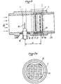
- the ion sensor with transit time consists of a metal casing 1, connected to ground by connection M, inside which flows the gas, the volume flow of which is Qv.
- the metal body 1 comprises two operating zones: a transmission zone 2 and a reception zone 3, spaced by a distance D.
- the emission zone 2 of the sensor is supplied by a high voltage pulse C coming from a high voltage block 4 and conveyed by the connection 5.
- the reception zone 3 of the sensor delivers a signal d via a connection 7, to a transit time detector 6.
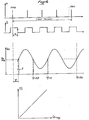
- This device 6 delivers at output on a connection 8 a signal marked e for a time t inversely proportional to the average volume flow rate QvmOY according to the curves of FIGS. 4 and 6 explained in the following description.
- a flywheel 9 secured to the engine crankshaft has four equidistant notches 9a. These notches 9a are detected by a position sensor 10 supplying a shaping block 11. At the output of block 11, pulses are obtained marked a whose spacing therefore corresponds to a quarter turn of the crankshaft. These pulses then undergo an angular delay by a microprocessor device 12 and according to a delay law called the shift law, to be transmitted by means of a connection 13 to the input of the devices 4 and 6. These pulses offset with respect to the signals a are marked b.
- the position sensor 10, the shaping block 11 and the block 4 delivering the high voltage pulses are known to those skilled in the art and already used in automotive electronics. They will not be described later in the presentation.
- FIG. 2 there are the elements constituting the emission 2 and reception 3 zones shown in FIG. 1.
- the emission zone 2 is composed of an ionization emission system 14, using the peak effect well known to those skilled in the art.
- This system 14 is maintained in the gas flow by an insulating bushing 15 screwed into the metal body 1 and immobilized in rotation by a nut 16.
- the reception area 3 consists of two grids 17 and 18 located on either side of the reception grid 19.
- the grid 17 is in the form of a metal mesh with fine meshes clamped between two metal shims 20 and 21.
- This grid 17 has a double role. First, it serves as electrostatic shielding between the receiving grid 19 and the emission system 14. As a result, the grid 19 is not influenced by the electric field existing between the part 14 and the internal part of the body 1 of the sensor connected to ground. Then, the grid 17 has a fine mesh weaving which allows it to break the swirls caused by the wake of the central member 14 and the internal part of the insulating bushing sensor 15. The grid 17 therefore has a regulatory role of aerodynamic flow which improves the stability of the electrical signal created by the influence of the ion cloud during its passage in front of the grid 19.
- the grid 18, located downstream of the grid 19, is also composed of a metal mesh with fine meshes of the same type as that of the grid 17 previously described.
- the gate 18 has an electrostatic shielding role with respect to the receiving gate 19; it also makes it possible to improve the shape of the signal induced on the reception grid.
- the reception grid 19, as shown in FIG. 2a also consists of a grid whose meshes are larger than those of the shielding grids 17 and 18.
- This grid 19 is encased in an insulating ring 22, it is electrically connected to an outlet, not shown in the figure, thus allowing the output of the induced signals.
- This grid 19 is held inside the ring 22 in four holding zones as shown in FIG. 2a so as to reduce parasitic capacities as much as possible. It should be noted that this grid 19, on which an electrical signal is induced by the influence of a moving cloud of ions, has a shape which is not necessarily circular.
- Metal wedges marked 20 and 21, located on either side of the first shielding grid 17, make it possible to adjust the distance D between the transmission system 2 and the reception system 3.
- the receiving system 3 composed of metal grids 17, 18 and 19 is held in place by a metal tip 23 fitted into the body 1 and thus constituting the other end of the sensor.
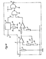
- fig. 3 are shown schematically the essential elements of the transit time detector 6 of FIG. 1 which outputs a signal marked e in fig. 4.
- the signal obtained on the receiving grid 19 and marked d in FIG. 4 is transmitted by connection 7 on the positive terminal of an operational amplifier 24.
- the input impedance of this element 24 is determined by resistors 25 and 26.
- the gain of amplifier 24 is a function of resistors 27 and 28.
- the amplified signal from 24 is transmitted to an amplifier marked 30 via a resistor 29 connected to the positive terminal.
- the negative terminal of 30 is connected to ground by a resistor 31, which thus achieves a comparator stage at zero.
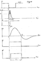
- t o the origin of time, that is to say the instant when we send the command, marked b, of the high voltage module, and t 1 as the instant where the signal collected on the gate 19 and marked d passes through zero
- marked f is therefore t1-t0.
- the signal marked c in fig. 4 represents the high voltage pulse sent to the transmission system 14. The ionization caused by this high voltage actually takes place only for a time A t0 corresponding to a high voltage greater than a threshold VO. There is therefore a delay between the command order of the high voltage and the effective creation of the ion cloud for a time A t0.
- the width of the signal marked f and equal to t1-t0 must therefore be corrected to take account of this delay in ionization.
- the block 32 comprising the elements 33 and 34, controlled by the order marked b and conveyed by the connection 13, fig. 1, is responsible for generating this delay.
- Block 32 is a monostable stage, of a type known per se, whose output signal g goes to state 0 for a time A t from the control order b.
- the signals marked f and g, respectively from 30 and 32, are sent on two successive "NAND " logic gates 35 and 36.
- the phenomenon of delay in the emission of the ion cloud is thus compensated for by measuring the real transit time.
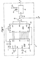
- Fig. 5 schematically represents the essential elements of block 12 of FIG. 1.
- This block 12 is responsible for delivering signals marked b shifted late by an angle ⁇ with respect to the signals coming from the flywheel and marked a.
- Block 12 includes four modules.
- Module 37 is the main element of the offset signal generation system. It is made with a 8748 type microprocessor. This integrates its program memory, a RAM memory necessary for calculating the delay and a counter. The program is sequenced by a quartz referenced 37a. The element marked 37b is a capacity whose role is to initialize the microprocessor at power-up.
- the delay angle to be generated is a function of the motor speed, to calculate this delay the microprocessor must know this constantly. To do this, it has a counter to quantify the time between two flywheel pulses marked a. These pulses are applied to the INT input of the microprocessor and are active on the low level. The microprocessor constantly monitors this input. When the signal goes low, the microprocessor checks the signal status a second time: if it is still low, the signal referenced a is validated; otherwise, it is ignored and a new measurement is started again.
- the role of the module 38 is to delay the flywheel pulses. To do this, the element 38 is made with three integrated counters of the type 8253 and programmable separately.
- the use of several counters is necessary because the delays generated are greater than 90 °; with three counters the maximum delays are 270 °.
- the meter loading procedure is carried out under microprocessor control. This transmits several pieces of information to module 38.
- the output WR of the microprocessor is activated thus informing the module 38 that the microprocessor will transmit information.
- the outputs referenced P20 and P21 are activated, they determine the counter to be loaded; the data previously calculated by the microprocessor is finally transmitted by its outputs marked DBO to DB7, the microprocessor deletes the information on its output WR thus signaling to the module 8253 that the loading procedure is finished.
- the selected counter is then decremented by means of a clock present on its CK input and coming from the ALE output of the microprocessor.
- this counter When this counter crosses zero, it activates its corresponding output OUT by keeping it low during a clock period (ALE).
- the element referenced 39 is a “NAND” gate with three inputs, the role of which is to add the three outputs OUT of the module 38 and reverse the parity.
- Element 40 is an AND gate with two inputs. It receives on one of them the output of module 39 and on the other the information referenced e coming from module 6, fig. 1.
- the role of module 40 is to avoid triggering a new flow measurement if the one previously started is not finished. This can happen at very low flow rates and high motor speed (motor deceleration).
- the module 41 is a monostable embodiment known per se. It provides a calibrated pulse referenced by the elements 41a and 41b. This pulse is generated each time its input B is activated. It is transmitted to the high voltage module 4 by the link 13, fig. 1.
- the constant phase ⁇ o can be achieved mechanically by shifting the flywheel sensor by an angle ⁇ o .
- the constant delay T. is produced electronically from elements of the monostable type of known embodiment. These monostables, three in number, will be triggered separately once every three impulses from the flywheel. Thus the use of the microprocessor, referenced 37, and counters, referenced 38, is then no longer necessary.
Landscapes
- Physics & Mathematics (AREA)
- Fluid Mechanics (AREA)
- General Physics & Mathematics (AREA)
- Measuring Volume Flow (AREA)
- Combined Controls Of Internal Combustion Engines (AREA)
Applications Claiming Priority (2)
| Application Number | Priority Date | Filing Date | Title |
|---|---|---|---|
| FR8020896 | 1980-09-30 | ||
| FR8020896A FR2491207A1 (fr) | 1980-09-30 | 1980-09-30 | Capteur ionique a temps de transit entre une zone d'emission et une zone de reception |
Publications (2)
| Publication Number | Publication Date |
|---|---|
| EP0049195A1 EP0049195A1 (fr) | 1982-04-07 |
| EP0049195B1 true EP0049195B1 (fr) | 1985-09-25 |
Family
ID=9246403
Family Applications (1)
| Application Number | Title | Priority Date | Filing Date |
|---|---|---|---|
| EP81401477A Expired EP0049195B1 (fr) | 1980-09-30 | 1981-09-23 | Capteur ionique à temps de transit entre une zone d'émission et une zone de réception |
Country Status (6)
| Country | Link |
|---|---|
| US (1) | US4409822A (enExample) |
| EP (1) | EP0049195B1 (enExample) |
| JP (1) | JPS57168116A (enExample) |
| DE (1) | DE3172435D1 (enExample) |
| ES (1) | ES8305923A1 (enExample) |
| FR (1) | FR2491207A1 (enExample) |
Families Citing this family (6)
| Publication number | Priority date | Publication date | Assignee | Title |
|---|---|---|---|---|
| FR2491618B1 (fr) * | 1980-10-07 | 1985-06-07 | Renault | Capteur ionique de debit a temps de transit de type differentiel |
| FR2560386B1 (fr) * | 1984-02-24 | 1986-07-11 | Renault | Conversion d'un signal fluctuant correspondant a un temps de transit entre deux reperes en une tension proportionnelle a la vitesse moyenne |
| GB2181553B (en) * | 1985-08-06 | 1990-03-07 | Nat Res Dev | Flow measurement/metering |
| RU2134423C1 (ru) * | 1997-04-09 | 1999-08-10 | Всероссийский электротехнический институт им.В.И.Ленина | Способ измерения модуля и направления вектора скорости разреженного газового потока и устройство для его осуществления |
| AT501993B1 (de) * | 2006-02-20 | 2007-06-15 | Guenter Dipl Ing Fh Weilguny | Vorrichtung für die messung der geschwindigkeit eines fluids |
| DE202014007778U1 (de) | 2014-09-17 | 2015-12-18 | Antonio Chiriatti | Kostengünstiges Luftgeschwindigkeitsmessgerät |
Family Cites Families (6)
| Publication number | Priority date | Publication date | Assignee | Title |
|---|---|---|---|---|
| US3693436A (en) * | 1970-08-28 | 1972-09-26 | Lab Data Control Inc | Liquid flow meter |
| GB1573102A (en) * | 1976-01-13 | 1980-08-13 | Lucas Industries Ltd | Gas flow transducers and i.c. engine control systems incorporating such transducers |
| JPS6047532B2 (ja) * | 1977-01-13 | 1985-10-22 | 日産自動車株式会社 | 流量計測装置 |
| US4127029A (en) * | 1977-04-25 | 1978-11-28 | La General De Fluides Geflu | Ionic measuring device |
| US4152935A (en) * | 1978-01-12 | 1979-05-08 | Nissan Motor Company, Limited | Mass flow measuring apparatus |
| FR2439302A1 (fr) * | 1978-10-20 | 1980-05-16 | Renault | Dispositif de mesure du remplissage volumique d'air d'un moteur |
-
1980
- 1980-09-30 FR FR8020896A patent/FR2491207A1/fr active Granted
-
1981
- 1981-09-23 DE DE8181401477T patent/DE3172435D1/de not_active Expired
- 1981-09-23 EP EP81401477A patent/EP0049195B1/fr not_active Expired
- 1981-09-29 US US06/306,761 patent/US4409822A/en not_active Expired - Fee Related
- 1981-09-29 ES ES505863A patent/ES8305923A1/es not_active Expired
- 1981-09-30 JP JP56154036A patent/JPS57168116A/ja active Pending
Also Published As
| Publication number | Publication date |
|---|---|
| FR2491207B1 (enExample) | 1984-10-26 |
| US4409822A (en) | 1983-10-18 |
| EP0049195A1 (fr) | 1982-04-07 |
| ES505863A0 (es) | 1983-04-16 |
| ES8305923A1 (es) | 1983-04-16 |
| DE3172435D1 (en) | 1985-10-31 |
| FR2491207A1 (fr) | 1982-04-02 |
| JPS57168116A (en) | 1982-10-16 |
Similar Documents
| Publication | Publication Date | Title |
|---|---|---|
| EP0496661B1 (fr) | Procédé et dispositif de mesure de vitesse d'écoulement instationnaire | |
| EP3087361B1 (fr) | Équipement de relève et de transmission de valeurs mesurées de température | |
| EP0049195B1 (fr) | Capteur ionique à temps de transit entre une zone d'émission et une zone de réception | |
| EP3278081B1 (fr) | Dispositif de comptage de particules | |
| FR2552876A1 (fr) | Systeme thermique de mesure de niveau de liquide | |
| FR2903142A1 (fr) | Procede de diagnostic d'un filtre a particules et dispositif pour sa mise en oeuvre | |
| FR2978493A1 (fr) | Procede et dispositif de mesure de la concentration de suies dans un gaz d'echappement, notamment d'un moteur a combustion interne | |
| FR2945632A1 (fr) | Capteur de mesure d'une grandeur de l'ecoulement d'un milieu | |
| FR2842904A1 (fr) | Procede permettant de determiner un flux massique d'air | |
| CA2556307C (fr) | Debitmetre instationnaire | |
| EP0703468B1 (fr) | Procédé et système de détermination des paramètres anémobaroclinométriques à bord d'un aéronef | |
| EP0050998B1 (fr) | Capteur ionique à temps de transit de type différentiel | |
| FR2572529A1 (fr) | Procede et dispositif pour controler des objets mono-cristallins, traverses par un rayonnement d'une source gamma | |
| EP4269953B1 (fr) | Mesure du débit à partir des impédances électriques des transducteurs piézoélectriques | |
| Turner et al. | The design and evaluation of an airborne optical ice particle counter | |
| EP0308324A1 (fr) | Cinémomètre à effet doppler de sécurité | |
| EP0919792A1 (fr) | Compteur de volume d'un fluide en écoulement | |
| CH406451A (fr) | Dispositif électrométrique | |
| FR2514959A1 (fr) | Dispositif laser emetteur-recepteur a detection heterodyne | |
| BE843239A (fr) | Capacimetre utilisable en particulier comme humidimetre | |
| FR2539872A1 (fr) | Dispositif de pyrometrie a radiations | |
| FR2473626A1 (fr) | Dispositif de commande, de regulation et de surveillance des moteurs a combustion interne | |
| FR2497875A1 (fr) | Ensemble de controle de consommation d'un moteur a combustion interne | |
| FR2461266A1 (fr) | Procede et appareil pour la mesure de rayonnements ionisants | |
| FR2459962A1 (fr) | Capteur de debit gazeux a fil chaud |
Legal Events
| Date | Code | Title | Description |
|---|---|---|---|
| PUAI | Public reference made under article 153(3) epc to a published international application that has entered the european phase |
Free format text: ORIGINAL CODE: 0009012 |
|
| 17P | Request for examination filed |
Effective date: 19810926 |
|
| AK | Designated contracting states |
Designated state(s): BE DE GB IT NL SE |
|
| ITF | It: translation for a ep patent filed | ||
| GRAA | (expected) grant |
Free format text: ORIGINAL CODE: 0009210 |
|
| AK | Designated contracting states |
Designated state(s): BE DE GB IT NL SE |
|
| REF | Corresponds to: |
Ref document number: 3172435 Country of ref document: DE Date of ref document: 19851031 |
|
| PLBE | No opposition filed within time limit |
Free format text: ORIGINAL CODE: 0009261 |
|
| STAA | Information on the status of an ep patent application or granted ep patent |
Free format text: STATUS: NO OPPOSITION FILED WITHIN TIME LIMIT |
|
| 26N | No opposition filed | ||
| PGFP | Annual fee paid to national office [announced via postgrant information from national office to epo] |
Ref country code: DE Payment date: 19890530 Year of fee payment: 9 |
|
| PGFP | Annual fee paid to national office [announced via postgrant information from national office to epo] |
Ref country code: SE Payment date: 19890821 Year of fee payment: 9 |
|
| PGFP | Annual fee paid to national office [announced via postgrant information from national office to epo] |
Ref country code: BE Payment date: 19890825 Year of fee payment: 9 |
|
| PGFP | Annual fee paid to national office [announced via postgrant information from national office to epo] |
Ref country code: GB Payment date: 19890831 Year of fee payment: 9 |
|
| ITTA | It: last paid annual fee | ||
| PGFP | Annual fee paid to national office [announced via postgrant information from national office to epo] |
Ref country code: NL Payment date: 19890930 Year of fee payment: 9 |
|
| PG25 | Lapsed in a contracting state [announced via postgrant information from national office to epo] |
Ref country code: GB Effective date: 19900923 |
|
| PG25 | Lapsed in a contracting state [announced via postgrant information from national office to epo] |
Ref country code: SE Effective date: 19900924 |
|
| PG25 | Lapsed in a contracting state [announced via postgrant information from national office to epo] |
Ref country code: BE Effective date: 19900930 |
|
| BERE | Be: lapsed |
Owner name: REGIE NATIONALE DES USINES RENAULT Effective date: 19900930 |
|
| PG25 | Lapsed in a contracting state [announced via postgrant information from national office to epo] |
Ref country code: NL Effective date: 19910401 |
|
| NLV4 | Nl: lapsed or anulled due to non-payment of the annual fee | ||
| GBPC | Gb: european patent ceased through non-payment of renewal fee | ||
| PG25 | Lapsed in a contracting state [announced via postgrant information from national office to epo] |
Ref country code: DE Effective date: 19910601 |
|
| EUG | Se: european patent has lapsed |
Ref document number: 81401477.5 Effective date: 19910527 |