EP0049101B1 - Internal combustion engine electrical systems - Google Patents
Internal combustion engine electrical systems Download PDFInfo
- Publication number
- EP0049101B1 EP0049101B1 EP81304378A EP81304378A EP0049101B1 EP 0049101 B1 EP0049101 B1 EP 0049101B1 EP 81304378 A EP81304378 A EP 81304378A EP 81304378 A EP81304378 A EP 81304378A EP 0049101 B1 EP0049101 B1 EP 0049101B1
- Authority
- EP
- European Patent Office
- Prior art keywords
- flywheel
- coil
- charging
- engine
- stator core
- Prior art date
- Legal status (The legal status is an assumption and is not a legal conclusion. Google has not performed a legal analysis and makes no representation as to the accuracy of the status listed.)
- Expired
Links
- 238000002485 combustion reaction Methods 0.000 title claims description 7
- 239000003990 capacitor Substances 0.000 claims description 27
- 230000008878 coupling Effects 0.000 claims description 5
- 238000010168 coupling process Methods 0.000 claims description 5
- 238000005859 coupling reaction Methods 0.000 claims description 5
- 239000007858 starting material Substances 0.000 claims description 3
- 230000000737 periodic effect Effects 0.000 claims description 2
- 230000002093 peripheral effect Effects 0.000 claims description 2
- 238000000926 separation method Methods 0.000 claims 2
- 230000004907 flux Effects 0.000 description 6
- 230000005347 demagnetization Effects 0.000 description 3
- 238000013459 approach Methods 0.000 description 2
- 230000000694 effects Effects 0.000 description 2
- 230000003534 oscillatory effect Effects 0.000 description 2
- XAGFODPZIPBFFR-UHFFFAOYSA-N aluminium Chemical compound [Al] XAGFODPZIPBFFR-UHFFFAOYSA-N 0.000 description 1
- 229910052782 aluminium Inorganic materials 0.000 description 1
- 238000010276 construction Methods 0.000 description 1
- 238000010586 diagram Methods 0.000 description 1
- 238000001914 filtration Methods 0.000 description 1
- 230000006872 improvement Effects 0.000 description 1
- 230000001939 inductive effect Effects 0.000 description 1
- 239000000696 magnetic material Substances 0.000 description 1
- 230000009467 reduction Effects 0.000 description 1
Images
Classifications
-
- F—MECHANICAL ENGINEERING; LIGHTING; HEATING; WEAPONS; BLASTING
- F02—COMBUSTION ENGINES; HOT-GAS OR COMBUSTION-PRODUCT ENGINE PLANTS
- F02P—IGNITION, OTHER THAN COMPRESSION IGNITION, FOR INTERNAL-COMBUSTION ENGINES; TESTING OF IGNITION TIMING IN COMPRESSION-IGNITION ENGINES
- F02P1/00—Installations having electric ignition energy generated by magneto- or dynamo- electric generators without subsequent storage
- F02P1/08—Layout of circuits
-
- F—MECHANICAL ENGINEERING; LIGHTING; HEATING; WEAPONS; BLASTING
- F02—COMBUSTION ENGINES; HOT-GAS OR COMBUSTION-PRODUCT ENGINE PLANTS
- F02B—INTERNAL-COMBUSTION PISTON ENGINES; COMBUSTION ENGINES IN GENERAL
- F02B63/00—Adaptations of engines for driving pumps, hand-held tools or electric generators; Portable combinations of engines with engine-driven devices
- F02B63/02—Adaptations of engines for driving pumps, hand-held tools or electric generators; Portable combinations of engines with engine-driven devices for hand-held tools
Definitions
- the present invention relates generally to internal combustion engine electrical systems and more particularly to a combined ignition- alternator arrangement for small electric start internal combustion engine powered devices.
- the invention provides an internal combustion engine having a flywheel, a storage battery, a battery energizable engine starter, and a high voltage engine ignition system including a pair of laminated stator core legs having their respective first ends in close proximity to the engine flywheel and their respective second ends magnetically coupled together with an ignition coil on one leg and with flywheel supported magnetic means including a single permanent magnet for magnetically coupling the leg first ends together each time the permanent magnet passes the cores as a part of the operation of the high voltage ignition system to induce an ignition voltage in the ignition coil, characterised by an arrangement providing periodic current surges for charging the storage battery during engine operation comprising a charging coil surrounding the other stator core leg, a rectifier in the form of a diode connected in series with the charging coil, and a capacitor connected directly in parallel with the charging coil and in series with the rectifier, the capacitor being of sufficient capacity relative to the inductance of the charging coil to cause the current in the parallel coil and capacitor circuit to lead the voltage thereacross, the parallel combination of the charging coil and capacitor being connected in
- the capacitor provided in parallel with the coil is required to be of substantial capacity in order to cause the current to lead the voltage across the coil as distinct from the small capacitors disclosed in the arrangement of German Patent Specification No. 2423472.
- the area under the primary charging pulse produced by the coil and also the secondary or “ringing" pulses are of greater magnitude both aspects contributing to significantly greater charging currents to the battery.
- a generally E-shaped ignition stator core has battery charging coils on each of the outer E-legs with capacitors paralleling the coils and diodes connected in series with each coil and capacitor, and the series circuits connected in parallel with one another and to a storage battery so that sequential primary charging current pulses are delivered to the battery during each revolution of an engine flywheel.
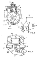
- the internal combustion engine 11 powers a device, such as a lawn-mower having an electric start feature, energized by a storage battery 13.
- the engine also has an ignition system including a sparkplug 15 which receives ignition pulses from a high voltage coil and associated circuitry J7 supported on a laminated stator core 19. The ignition pulses are induced by passage of a permanent magnet 21 supported on the engine flywheel 23.
- the engine as illustrated in Fig. 1 is generally of conventional construction and of a type currently commercially available.
- Flywheel 23 is fastened to the engine crankshaft 25 and may include a counterbalancing weight 27 as well as peripheral teeth (not shown) engageable by a battery energizable engine starter.
- Crankshaft 25 is of course also coupled to the engine powered device, for example a lawnmower.
- stator core 19 is seen to be a three legged E shaped laminated stator core having outer legs 29 and 31 and a central leg 33 disposed between the outer legs. Respective first ends of the three legs are in close proximity to the engine flywheel 23 while the other ends of each of the legs are coupled together magnetically by base portion 35 of the E shaped core.
- Leg 33 supports the ignition circuitry 17 including an ignition coil while flywheel 23 supports permanent magnet 21 and connecting pole shoes 37 and 39 creating a north pole at the surface of one of those shoes and a south pole at the surface of the other.
- the permanent magnet is poled in the tangential direction with the flywheel being otherwise fabricated from a non-magnetic material, such as cast aluminum, so that when the flywheel rotates in the direction indicated by the arrow, stator core legs 31 and 33 are magnetically coupled together and thereafter when the flywheel reaches the position illustrated in Fig. 2, stator core legs 33 and 29 are magnetically coupled together.
- a flux reversal occurs in stator core leg 33, inducing an ignition voltage in the ignition coil.
- Capacitor discharge, as well as mechanical or electronic interrupt type ignition circuits may for example be employed and further details of the ignition circuitry 17 are omitted for clarity.
- the trickle charger of the present invention employs one or more charging coils, such as 41 and 43 of Fig. 3. Each coil is connected in series with a corresponding diode 45 or 47 and the series coil-diode combinations are connected in parallel and by line 49 to form a closed loop circuit with the battery 13.
- the coils 41 and 43 may, as illustrated in Fig. 2, be positioned on the outer legs of the E shaped core.
- the effective charging current for a given coil configuration is improved by providing capacitors 51 and 53 of Fig. 3 in parallel with respective coils 41 and 43.
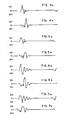
- Figs. 6 and 7 are analogous respectively to Figures 4 and 5 but depict the improvement in coil voltage waveforms due to the addition of capacitors 51 and 53 of the present invention. It should be noted that with the capacitors paralleling the coils, not only is the area under the primary charging pulse greater, but also the secondary or ringing pulses are of greater magnitude with both aspects contributing to greater effective charging current.
- the connection of the capacitance provides an increase effective charging current by reducing the demagnetization magnetomotive forces within the magnetic core 19. Demagnetization occurs because of the magnetomotive force that produces flux in the core that tends to oppose the flux produced by the magnet.
- the capacitor is preferably selected to have sufficient capacity relative to the charging coil with which it is to be connected to cause the current through the parallel coil and capacitor circuit to lead the voltage thereacross.
Landscapes
- Engineering & Computer Science (AREA)
- Chemical & Material Sciences (AREA)
- Combustion & Propulsion (AREA)
- Mechanical Engineering (AREA)
- General Engineering & Computer Science (AREA)
- Ignition Installations For Internal Combustion Engines (AREA)
- Permanent Magnet Type Synchronous Machine (AREA)
Description
- The present invention relates generally to internal combustion engine electrical systems and more particularly to a combined ignition- alternator arrangement for small electric start internal combustion engine powered devices.
- It is known from U.S. Patent Specification No. 4061121 to incorporate an alternator arrangement in an engine ignition system, the alternator being of a large scale and having numerous coils inter-connected to provide the continuous output of several amps, the output being rectified for battery charging purposes. It is also known from French Patent Specification No. 2009850 to provide a multi-leg ignition core solely for an engine ignition system and it is known from German Patent Specification No. 2423272 to provide capacitors in parallel with an alternator and prior to a rectifier of a battery charging system, one capacitor being for filtering purposes whilst the other protects the circuit against high frequency voltage surges. Such capacitors would need only to be of small value to provide those functions.
- The invention provides an internal combustion engine having a flywheel, a storage battery, a battery energizable engine starter, and a high voltage engine ignition system including a pair of laminated stator core legs having their respective first ends in close proximity to the engine flywheel and their respective second ends magnetically coupled together with an ignition coil on one leg and with flywheel supported magnetic means including a single permanent magnet for magnetically coupling the leg first ends together each time the permanent magnet passes the cores as a part of the operation of the high voltage ignition system to induce an ignition voltage in the ignition coil, characterised by an arrangement providing periodic current surges for charging the storage battery during engine operation comprising a charging coil surrounding the other stator core leg, a rectifier in the form of a diode connected in series with the charging coil, and a capacitor connected directly in parallel with the charging coil and in series with the rectifier, the capacitor being of sufficient capacity relative to the inductance of the charging coil to cause the current in the parallel coil and capacitor circuit to lead the voltage thereacross, the parallel combination of the charging coil and capacitor being connected in series with the rectifier and battery to form a closed loop circuit for charging the battery.
- The capacitor provided in parallel with the coil is required to be of substantial capacity in order to cause the current to lead the voltage across the coil as distinct from the small capacitors disclosed in the arrangement of German Patent Specification No. 2423472. By causing the current to lead the voltage output across the coil in accordance with the invention the area under the primary charging pulse produced by the coil and also the secondary or "ringing" pulses are of greater magnitude both aspects contributing to significantly greater charging currents to the battery.
- Also in general and in one form of the invention, a generally E-shaped ignition stator core has battery charging coils on each of the outer E-legs with capacitors paralleling the coils and diodes connected in series with each coil and capacitor, and the series circuits connected in parallel with one another and to a storage battery so that sequential primary charging current pulses are delivered to the battery during each revolution of an engine flywheel.
- A system similar to that of the present invention is described in EP-A-0049102 in which the same priority date is claimed. In this system, however, a fourth stator core leg is provided.
- The following is a description of some specific embodiments of the invention, reference being made to the accompanying drawings in which:
- Fig. 1 is a plan view of an internal combustion engine having an ignition stator structure mounted closely adjacent the engine flywheel;
- Fig. 2 illustrates the stator and a portion of the flywheel of Fig. 1 in greater detail;
- Fig. 3 is a schematic diagram illustrating the battery charging circuitry associated with Figs. 1 and 2 in accordance with the present invention;
- Figs. 4a and 4b illustrate the open circuit voltage waveforms measured across each of the pair of coils without the parallel capacitors;
- Figs. 5a and 5b are the corresponding voltage waveforms measured across each of the pair of coils without the parallel capacitors when the circuit is under load as when charging the battery;
- Figs. 6a and 6b illustrate the open circuit voltage waveforms measured across each of the pair of coils with the capacitors connected in parallel as illustrated in Fig. 3 in accordance with the present invention; and
- Figs. 7a and 7b illustrate the corresponding voltage waveforms measured across each of the pair of coils with the capacitors connected in parallel when the circuit is under load in accordance with the present invention.
- Corresponding reference characters indicate corresponding parts throughout the several views of the drawing.
- Referring to the drawing generally, the internal combustion engine 11 powers a device, such as a lawn-mower having an electric start feature, energized by a
storage battery 13. The engine also has an ignition system including asparkplug 15 which receives ignition pulses from a high voltage coil and associated circuitry J7 supported on a laminatedstator core 19. The ignition pulses are induced by passage of apermanent magnet 21 supported on theengine flywheel 23. The engine as illustrated in Fig. 1 is generally of conventional construction and of a type currently commercially available. Flywheel 23 is fastened to the engine crankshaft 25 and may include a counterbalancingweight 27 as well as peripheral teeth (not shown) engageable by a battery energizable engine starter. Crankshaft 25 is of course also coupled to the engine powered device, for example a lawnmower. - Referring now to Fig. 2,
stator core 19 is seen to be a three legged E shaped laminated stator core havingouter legs 29 and 31 and acentral leg 33 disposed between the outer legs. Respective first ends of the three legs are in close proximity to theengine flywheel 23 while the other ends of each of the legs are coupled together magnetically bybase portion 35 of the E shaped core. Leg 33 supports theignition circuitry 17 including an ignition coil while flywheel 23 supportspermanent magnet 21 and connectingpole shoes 37 and 39 creating a north pole at the surface of one of those shoes and a south pole at the surface of the other. The permanent magnet is poled in the tangential direction with the flywheel being otherwise fabricated from a non-magnetic material, such as cast aluminum, so that when the flywheel rotates in the direction indicated by the arrow,stator core legs 31 and 33 are magnetically coupled together and thereafter when the flywheel reaches the position illustrated in Fig. 2,stator core legs stator core leg 33, inducing an ignition voltage in the ignition coil. Capacitor discharge, as well as mechanical or electronic interrupt type ignition circuits may for example be employed and further details of theignition circuitry 17 are omitted for clarity. - Electrically the trickle charger of the present invention employs one or more charging coils, such as 41 and 43 of Fig. 3. Each coil is connected in series with a
corresponding diode line 49 to form a closed loop circuit with thebattery 13. Thecoils - In Fig. 2, as
flywheel 23 rotates in a clockwise direction, pole shoe 37 approaches the closely adjacent end of stator core leg 31, moving past that leg and approaching the free end ofstator core leg 33. At the time when thelegs 31 and 33 are spanned by thepole shoes 37 and 39, the flux through stator core leg 31 is at a maximum, and continued flywheel rotation results in a decrease in that flux. Thus, as the magnetic member of the flywheel approaches and passes the pair oflegs 31 and 33, a pulse first in one direction and then of opposite polarity is induced incoil 41, as illustrated in Fig. 4a. Thediode 45 functions to pass only one polarity of this pulse to the battery with the voltage wave-form acrosscoil 41 when loaded by the battery being illustrated in Fig. 5a. In practice, several other pulses of lesser magnitude are also induced by thecoil 41 and conveyed to the battery, however, the major portion of the charging current is provided by the single induced pulse passed by thediode 45 to the battery. As the flywheel continues to rotate, this same effect is noticed betweenlegs diode 47 to thebattery 13. Again, several lesser pulses also pass through the diode to the battery. - Comparing Figs. 4a and 4b or Figs. 5a and 5b, it will be noted that the voltage waveform is somewhat oscillatory after the primary charging pulse for
coil 41 whereas this voltage waveform is preceded by the oscillatory behaviour forcoil 43. This phenomenon is apparently due to the reluctance reducing contribution of the third stator core leg not primarily involved in producing the output voltage. Comparing Figs. 4a and 5a, or Figs. 4b and 5b, it will be noted that loading the charging coils as by coupling them tobattery 13 has little effect on the lower half of the waveform since the respective diodes are not passing current to the battery during that time, however, the primary charging pulse has its peak substantially reduced by loading the respective coils. - In accordance with the present invention, the effective charging current for a given coil configuration is improved by providing
capacitors respective coils - Figs. 6 and 7 are analogous respectively to Figures 4 and 5 but depict the improvement in coil voltage waveforms due to the addition of
capacitors magnetic core 19. Demagnetization occurs because of the magnetomotive force that produces flux in the core that tends to oppose the flux produced by the magnet. By providing the parallel capacitor connection, the current through the capacitor-coil circuit leads the voltage, and this reduces the reduction in flux or "demagnetization". Thus the capacitor is preferably selected to have sufficient capacity relative to the charging coil with which it is to be connected to cause the current through the parallel coil and capacitor circuit to lead the voltage thereacross.
Claims (3)
Applications Claiming Priority (2)
| Application Number | Priority Date | Filing Date | Title |
|---|---|---|---|
| US06/190,899 US4383214A (en) | 1980-09-25 | 1980-09-25 | Magneto battery trickle charger |
| US190899 | 1980-09-25 |
Publications (2)
| Publication Number | Publication Date |
|---|---|
| EP0049101A1 EP0049101A1 (en) | 1982-04-07 |
| EP0049101B1 true EP0049101B1 (en) | 1984-11-28 |
Family
ID=22703252
Family Applications (1)
| Application Number | Title | Priority Date | Filing Date |
|---|---|---|---|
| EP81304378A Expired EP0049101B1 (en) | 1980-09-25 | 1981-09-23 | Internal combustion engine electrical systems |
Country Status (7)
| Country | Link |
|---|---|
| US (1) | US4383214A (en) |
| EP (1) | EP0049101B1 (en) |
| JP (1) | JPS5765261A (en) |
| AU (1) | AU525903B2 (en) |
| CA (1) | CA1147803A (en) |
| DE (1) | DE3167489D1 (en) |
| ZA (1) | ZA814416B (en) |
Families Citing this family (6)
| Publication number | Priority date | Publication date | Assignee | Title |
|---|---|---|---|---|
| JPS60243301A (en) * | 1984-05-18 | 1985-12-03 | Mitsubishi Electric Corp | Scroll fluid machine |
| US4914372A (en) * | 1988-09-21 | 1990-04-03 | Tanaka Kogyo Co., Ltd. | Small engine for hand-held work machines |
| FR2673204B1 (en) * | 1991-02-25 | 1995-03-24 | Picardie Lainiere | COMPOSITE LINING TEXTILE AND MANUFACTURING METHOD THEREOF. |
| US20070052392A1 (en) * | 2005-09-08 | 2007-03-08 | Elliott Galynsky | Method and apparatus for trickle-charging batteries |
| US10941745B2 (en) * | 2015-07-21 | 2021-03-09 | Walbro Llc | Ignition system for light-duty combustion engine |
| CN106787030A (en) * | 2017-03-28 | 2017-05-31 | 安徽易威斯新能源科技股份有限公司 | A kind of new-energy automobile charging pile |
Family Cites Families (9)
| Publication number | Priority date | Publication date | Assignee | Title |
|---|---|---|---|---|
| US2609528A (en) * | 1948-12-17 | 1952-09-02 | Hartford Nat Bank & Trust Co | Device comprising an alternating current generator having permanent field magnets |
| US2900591A (en) * | 1958-02-12 | 1959-08-18 | Syncro Corp | Generator regulator system |
| US3009092A (en) * | 1959-07-29 | 1961-11-14 | Syncro Corp | Generator system |
| US3134038A (en) * | 1962-06-04 | 1964-05-19 | Syncro Corp | Combined inductance-capacitance unit for permanent magnet alternator |
| US3598098A (en) * | 1968-05-02 | 1971-08-10 | Bosch Gmbh Robert | Ignition arrangment for internal combustion engines |
| US3623467A (en) * | 1969-11-24 | 1971-11-30 | Phelon Co Inc | Triggering magnet and coil assembly for use with an ignition system including a permanent magnet alternator |
| DE2423472A1 (en) * | 1973-05-14 | 1974-12-05 | Needs Inc | LIGHTING SYSTEM |
| US4061121A (en) * | 1975-04-30 | 1977-12-06 | Tecumseh Products Company | Magneto-alternator with magneto energy limiting |
| US4213436A (en) * | 1978-09-13 | 1980-07-22 | R. E. Phelon Company, Inc. | Capacitor discharge ignition and alternator auxiliary power system |
-
1980
- 1980-09-25 US US06/190,899 patent/US4383214A/en not_active Expired - Lifetime
-
1981
- 1981-05-22 CA CA000378110A patent/CA1147803A/en not_active Expired
- 1981-06-30 ZA ZA814416A patent/ZA814416B/en unknown
- 1981-08-10 JP JP56125156A patent/JPS5765261A/en active Pending
- 1981-09-11 AU AU75187/81A patent/AU525903B2/en not_active Ceased
- 1981-09-23 DE DE8181304378T patent/DE3167489D1/en not_active Expired
- 1981-09-23 EP EP81304378A patent/EP0049101B1/en not_active Expired
Also Published As
| Publication number | Publication date |
|---|---|
| AU525903B2 (en) | 1982-12-09 |
| DE3167489D1 (en) | 1985-01-10 |
| US4383214A (en) | 1983-05-10 |
| AU7518781A (en) | 1982-04-01 |
| EP0049101A1 (en) | 1982-04-07 |
| ZA814416B (en) | 1982-09-29 |
| JPS5765261A (en) | 1982-04-20 |
| CA1147803A (en) | 1983-06-07 |
Similar Documents
| Publication | Publication Date | Title |
|---|---|---|
| US4404513A (en) | Economical flywheel alternator for trickle charging a small lawnmower battery | |
| US4873962A (en) | High efficiency electrical alternator system | |
| EP0049102B1 (en) | Internal combustion engine electrical systems | |
| US4325350A (en) | Alternator-powered breakerless capacitor discharge ignition system having improved low-speed timing characteristics | |
| US4383214A (en) | Magneto battery trickle charger | |
| US3824976A (en) | Capacitor charge-discharge type ignition system for use in a two-cycle internal combustion engine | |
| US6009865A (en) | Low speed ignition system | |
| JPS624549B2 (en) | ||
| US5606958A (en) | Ignition system for an internal-combustion engine, particularly for use in a chain saw or the like | |
| JPH06100170B2 (en) | Magneto ignition device | |
| US3861373A (en) | Magneto ignition system for internal combustion engines | |
| US4417195A (en) | Magneto battery trickle charger | |
| US4746825A (en) | Alternator core attachment | |
| US4351286A (en) | Coil assembly for an ignition system | |
| GB2086146A (en) | Charging arrangement for storage battery of an i.c. engine device | |
| US5806503A (en) | Discharge ignition apparatus for internal combustion engine having stepped spark advance | |
| EP0359850B1 (en) | Small engine for hand-held work machines | |
| JPS6067769A (en) | Ignitor of engine | |
| EP0300551A2 (en) | Electronic ignition device for internal combustion engines | |
| CA1307312C (en) | Small engine for hand-held work machines | |
| JPS6334476Y2 (en) | ||
| JPS6233510Y2 (en) | ||
| JPH0631600B2 (en) | Non-contact ignition device for internal combustion engine | |
| JPH01174246A (en) | Ac generator | |
| JPH0222236B2 (en) |
Legal Events
| Date | Code | Title | Description |
|---|---|---|---|
| PUAI | Public reference made under article 153(3) epc to a published international application that has entered the european phase |
Free format text: ORIGINAL CODE: 0009012 |
|
| AK | Designated contracting states |
Designated state(s): DE FR IT |
|
| 17P | Request for examination filed |
Effective date: 19820403 |
|
| ITF | It: translation for a ep patent filed | ||
| GRAA | (expected) grant |
Free format text: ORIGINAL CODE: 0009210 |
|
| AK | Designated contracting states |
Designated state(s): DE FR IT |
|
| REF | Corresponds to: |
Ref document number: 3167489 Country of ref document: DE Date of ref document: 19850110 |
|
| ET | Fr: translation filed | ||
| PLBE | No opposition filed within time limit |
Free format text: ORIGINAL CODE: 0009261 |
|
| STAA | Information on the status of an ep patent application or granted ep patent |
Free format text: STATUS: NO OPPOSITION FILED WITHIN TIME LIMIT |
|
| 26N | No opposition filed | ||
| PGFP | Annual fee paid to national office [announced via postgrant information from national office to epo] |
Ref country code: FR Payment date: 19900928 Year of fee payment: 10 |
|
| ITTA | It: last paid annual fee | ||
| PGFP | Annual fee paid to national office [announced via postgrant information from national office to epo] |
Ref country code: DE Payment date: 19901029 Year of fee payment: 10 |
|
| PG25 | Lapsed in a contracting state [announced via postgrant information from national office to epo] |
Ref country code: FR Effective date: 19920529 |
|
| PG25 | Lapsed in a contracting state [announced via postgrant information from national office to epo] |
Ref country code: DE Effective date: 19920602 |
|
| REG | Reference to a national code |
Ref country code: FR Ref legal event code: ST |