EP0048865B1 - Method of recognizing digital data when using a digital data transmission, particularly a data transmission in mobile radio communication systems - Google Patents
Method of recognizing digital data when using a digital data transmission, particularly a data transmission in mobile radio communication systems Download PDFInfo
- Publication number
- EP0048865B1 EP0048865B1 EP81107157A EP81107157A EP0048865B1 EP 0048865 B1 EP0048865 B1 EP 0048865B1 EP 81107157 A EP81107157 A EP 81107157A EP 81107157 A EP81107157 A EP 81107157A EP 0048865 B1 EP0048865 B1 EP 0048865B1
- Authority
- EP
- European Patent Office
- Prior art keywords
- sampling
- information
- pulse
- information element
- error rate
- Prior art date
- Legal status (The legal status is an assumption and is not a legal conclusion. Google has not performed a legal analysis and makes no representation as to the accuracy of the status listed.)
- Expired
Links
Images
Classifications
-
- H—ELECTRICITY
- H04—ELECTRIC COMMUNICATION TECHNIQUE
- H04L—TRANSMISSION OF DIGITAL INFORMATION, e.g. TELEGRAPHIC COMMUNICATION
- H04L25/00—Baseband systems
- H04L25/02—Details ; arrangements for supplying electrical power along data transmission lines
- H04L25/06—Dc level restoring means; Bias distortion correction ; Decision circuits providing symbol by symbol detection
- H04L25/068—Dc level restoring means; Bias distortion correction ; Decision circuits providing symbol by symbol detection by sampling faster than the nominal bit rate
-
- H—ELECTRICITY
- H04—ELECTRIC COMMUNICATION TECHNIQUE
- H04L—TRANSMISSION OF DIGITAL INFORMATION, e.g. TELEGRAPHIC COMMUNICATION
- H04L1/00—Arrangements for detecting or preventing errors in the information received
- H04L1/20—Arrangements for detecting or preventing errors in the information received using signal quality detector
Description
Die vorliegende Erfindung betrifft ein Verfahren zur Erkennung von Digitalinformation bei einer digitalen Informationsübertragung, insbesondere Informationsübertragung in Mobilfunk-Kommunikationssystemen, und eine Schaltungsanordnung zur Durchführung des Verfahrens.The present invention relates to a method for recognizing digital information in a digital information transmission, in particular information transmission in mobile radio communication systems, and a circuit arrangement for carrying out the method.
Sprache, Daten und Bild sind die Informationsformen, die in bekannten, drahtgebundenen Kommunikationssystemen und in zukünftigen Mobilfunk-Kommunikationssystemen zu übertragen sind. Bei einer Übertragung von Information, insbesondere digitalisierter Information in einem Mobilfunk-Kommunikationssystem, besteht ein Problem darin, dass durch sog. Mehrwegausbreitung auf dem Funkweg das bekannte Fading entsteht, das während eines Übertragungsvorgangs Bitfehler verursachen kann.Speech, data and images are the forms of information that are to be transmitted in known, wired communication systems and in future mobile radio communication systems. A problem with the transmission of information, in particular digitized information in a mobile radio communication system, is that so-called multipath propagation on the radio path results in the known fading, which can cause bit errors during a transmission process.
Es sind Verfahren bekannt, mittels derer auf der jeweiligen Empfängerseite aus der dort zur Verfügung stehenden Digitalinformation ein Abtastimpuls abgeleitet wird und dieser Abtastpuls dazu verwendet wird, einen Abtastzeitpunkt in den jeweiligen Bereich eines Informationselementes zu legen, in dem der abzutastende, dieses Informationselement repräsentierende Impuls seinen vermutbaren quasistationären Zustand einnimmt, vgl. beispielsweise DE-B- 1 804 719. Diese bekannten Verfahren haben jedoch den Nachteil, dass in solchen Fällen, in denen Informationselemente repräsentierende Impulse durch Störeinflüsse in der Amplitude und/oder in der Phase verzerrt werden, gerade zu dem Entscheidungszeitpunkt einen Bitfehler vortäuschen können, obwohl der betreffende Impuls insgesamt betrachtet fehlerfrei sein kann.Methods are known by means of which a scanning pulse is derived on the respective receiver side from the digital information available there and this scanning pulse is used to place a sampling time in the respective area of an information element in which the pulse to be scanned representing this information element is located assumes a quasi-steady state, cf. for example DE-B-1 804 719. However, these known methods have the disadvantage that, in those cases in which pulses representing information elements are distorted in amplitude and / or phase by interference, a bit error can be simulated precisely at the time of the decision, although the pulse in question can be error-free overall.
In den bisher konzipierten Mobilfunk-Kommunikationssystemen wird eine möglichst günstige Bitfehlerrate durch Anwendung unterschiedlicher Codierungsverfahren, beispielsweise «Forward Error Correcting», angestrebt. Diese Philosophie steht jedoch dem Bestreben entgegen, eine Vereinheitlichung der Betriebsweisen zu erreichen.In the previously designed mobile radio communication systems, the best possible bit error rate is aimed at by using different coding methods, for example “forward error correcting”. This philosophy, however, stands in the way of trying to standardize the operating methods.
Aus der US-A-3 366 930 ist ein Verfahren zur Erkennung von Digitalinformationen bei einer digitalen Informationsübertragung bekannt, bei dem mehrere Abtastpulse aus der empfangsseitig zur Verfügung stehenden Digitalinformation mit vorzugsweise einem ganzzahligen Vielfachen der Informationstakt-Frequenz abgeleitet werden und bei dem die Abtastzeitpunkte in den jeweiligen Bereich eines Informationselementes gelegt sind, in dem der abzutastende, dieses Informationselement repräsentierende Impuls seinen vermutbaren quasi-stationären Zustand einnimmt. Bei diesem bekannten Verfahren ist vorgesehen, dass die Flanken der Abtastpulse an entsprechend vielen Abtastzeitpunkten innerhalb eines weiter gespannten Zeitbereiches des das Informationselement repräsentierenden Impulses gelegt sind, dass jeweils ein Vergleich eines ersten Abtastergebnisses mit einem oder mehreren folgenden Abtastergebnissen durchgeführt wird und dass eine Mehrheitsentscheidung aufgrund der vorliegenden Abtastergebnisse getroffen wird.From US-A-3 366 930 a method for recognizing digital information in digital information transmission is known, in which a plurality of sampling pulses are derived from the digital information available at the receiving end, preferably with an integer multiple of the information clock frequency, and in which the sampling times in the respective area of an information element is placed, in which the pulse to be scanned representing this information element assumes its presumable quasi-stationary state. In this known method it is provided that the edges of the sampling pulses are placed at a corresponding number of sampling times within a wider span of time of the pulse representing the information element, that a comparison of a first sampling result with one or more subsequent sampling results is carried out and that a majority decision is made on the basis of the existing scanning results is taken.
Dieses bekannte Verfahren bietet keine Möglichkeit, einen aus mehreren möglichen Abtastmodi zur Erlangung einer erreichbaren kleinsten Fehlerbitrate anzuwenden.This known method does not offer the possibility of using one of several possible sampling modes in order to obtain the lowest error bit rate that can be achieved.
Der vorliegenden Erfindung liegt die Aufgabe zugrunde, ein Verfahren zur Erkennung von Digitalinformation bei einer digitalen Informationsübertragung der genannten Art zu schaffen, mittels dessen günstige Fehlerbitraten erzielt werden können, ohne einen der zuvor genannten Nachteile in Kauf nehmen zu müssen.The present invention has for its object to provide a method for recognizing digital information in a digital information transmission of the type mentioned, by means of which favorable error bit rates can be achieved without having to accept one of the aforementioned disadvantages.
Die der Erfindung zugrundeliegende Aufgabe wird durch ein Verfahren zur Erkennung von Digitalinformation bei einer digitalen Informationsübertragung, insbesondere Informationsübertragung in Mobilfunkkommunikationssystemen, bei dem mehrere Abtastimpulse aus der empfangsseitig zur Verfügung stehenden Digitalinformation mit vorzugsweise einem ganzzahligen Vielfachen der Informationstaktfrequenz abgeleitet werden und bei dem die Abtastzeitpunkte in den jeweiligen Bereich eines Informationselementes gelegt sind, in dem der abzutastende, dieses Informationselement repräsentierende Impuls seinen vermutbaren quasistationären Zustand einnimmt, wobei zumindest ein weiterer Abtastpuls aus der empfangsseitig zur Verfügung stehenden Digitalinformation abgeleitet wird, der ein weiteres ganzzahliges Vielfaches der Informationstaktfrequenz aufweist, wobei weitere Flanken des Abtastpulses an entsprechend vielen Abtastzeitpunkten innerhalb eines weitergespannten Abtastbereiches des das Informationselement repräsentierenden Impulses gelegt sind und wobei jeweils ein Vergleich eines ersten Abtastergebnisses mit einem oder mehreren folgenden Abtastergebnissen für ein individuelles Informationselement durchgeführt wird, gelöst, das dadurch gekennzeichnet ist, dass verschiedene Abtastmodi verwendet werden, unter denen durch Vergleich der Abtastergebnisse für ein individuelles Informationselement derjenige Abtastmodus herausgesucht wird, der die kleinste erkannte Informationsbitfehlerrate aufweist.The object on which the invention is based is achieved by a method for recognizing digital information in a digital information transmission, in particular information transmission in mobile radio communication systems, in which several scanning pulses are derived from the digital information available at the receiving end, preferably with an integral multiple of the information clock frequency, and in which the sampling times in the the respective area of an information element in which the pulse to be scanned, which represents this information element, assumes its presumable quasi-stationary state, at least one further scanning pulse being derived from the digital information available at the receiving end, which has a further integer multiple of the information clock frequency, with further edges of the Sampling pulse at a corresponding number of sampling times within a wider scanning range of the information element nt representing the impulse and in each case a comparison of a first scanning result with one or more subsequent scanning results for an individual information element is carried out, which is characterized in that different scanning modes are used, among which by comparing the scanning results for an individual information element Search mode is selected that has the smallest detected information bit error rate.
Die vorliegende Erfindung bietet den Vorteil, dass auf einfache Weise eine Mehrfachabtastung der Informationselemente durchführbar ist und an sich insgesamt fehlerfreie, jedoch verzerrte Informationselemente repräsentierende Impulse als fehlerfrei akzeptiert werden können, so dass die Informationsübertragung einen höheren Nutzeffekt erfährt.The present invention offers the advantage that multiple scanning of the information elements can be carried out in a simple manner, and impulses that are generally error-free, but represent distorted information elements, can be accepted as error-free, so that the information transmission has a higher useful effect.
Vorteilhafte Weiterbildungen der Erfindung sind durch die in den Unteransprüchen angegebenen Merkmale gekennzeichnet.Advantageous developments of the invention are characterized by the features specified in the subclaims.
Im folgenden wird die Erfindung anhand mehrerer, ein bevorzugtes Ausführungsbeispiel für die Erfindung betreffender Figuren im einzelnen erläutert.
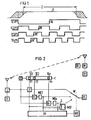
- Fig. 1 zeigt das Diagramm eines Informationsimpulses mit verschiedenen Abtastimpulsen.
- Fig. 2 zeigt das Blockschaltbild eines bevorzugten Ausführungsbeispiels für eine Schaltungsanordnung zur Durchführung des erfindungsgemässen Verfahrens.
- Fig. 1 shows the diagram of an information pulse with different sampling pulses.
- Fig. 2 shows the block diagram of a preferred embodiment for a circuit arrangement for carrying out the method according to the invention.
In der empfängerseitigen Schaltungsanordnung zur Durchführung des Verfahrens sind ein Demodulator D, ein Trägerfrequenzgenerator TF, verschiedene, nicht korrelierende Takterzeugungseinrichtungen TE1, TE2...TEn, mehrere Mehrheitsentscheidungsstufen ME2...MEn, eine Fehlerraten-Auswertungseinrichtung FA, eine Mehrheitsentscheidungsstufe zur Beurteilung der mittleren Fehlerrate MEF, eine Wählvorrichtung W, eine Wählvorrichtungssteuerung WS, eine Einrichtung zur Erzeugung eines Stellkriteriums für eine Zeitbereichseinstellung SZ sowie die Informationssenke IS vorgesehen. Senderseitig sind an sich bekannte, nur zum Verständnis der Zusammenhänge gezeigte Einrichtungen, wie eine Informationsquelle 10, ein Trägerfrequenzgenerator TF und ein Modulator M dargestellt, vgl. Figur 2.The receiver-side circuit arrangement for carrying out the method includes a demodulator D, a carrier frequency generator TF, various non-correlating clock generation devices TE1, TE2 ... TEn, a plurality of majority decision stages ME2 ... MEn, an error rate evaluation unit FA, a majority decision stage for assessing the average Error rate MEF, a selector W, a selector control WS, a device for generating a setting criterion for a time range setting SZ and the information sink IS are provided. Devices known per se and shown only for understanding the relationships, such as an information source 10, a carrier frequency generator TF and a modulator M, are shown on the transmitter side, cf. Figure 2.
Zum optimalen Abtasten eines ein Informationselement repräsentierenden Impulses, vgl. Fig. 1, ist erfindungsgemäss vorgesehen, dass ausser dem aus der eintreffenden Digital-Information abgeleiteten Abtastpuls, der in einer ersten Takterzeugungseinrichtung TE1 erzeugt wird, weitere Abtastpulse mit jeweils einer höheren Frequenz im Vergleich zu der Frequenz der ersten Takterzeugungseinrichtung TE1 mittels weiterer Takterzeugungseinrichtungen TE2 ...TEn erzeugt werden. Mit den verschiedenen zur Verfügung gestellten Abtastpulsen können unterschiedliche Abtastmodi für das Abtasten des das Informationselement repräsentierenden Impulses zur Anwendung kommen.For the optimal sampling of a pulse representing an information element, cf. 1, it is provided according to the invention that, in addition to the sampling pulse derived from the incoming digital information, which is generated in a first clock generating device TE1, further scanning pulses each having a higher frequency in comparison to the frequency of the first clock generating device TE1 by means of further clock generating devices TE2. ..TEn are generated. With the different scanning pulses provided, different scanning modes can be used for scanning the pulse representing the information element.
Aus Fig. 1 geht hervor, dass der das Informationselement repräsentierende Impuls in unterschiedlich breiten Abtastbereichen mittels der unterschiedlichen Abtastpulse P1, P2...Pn zu unterschiedlichen Abtastzeitpunkten PA,PA' abgetastet werden kann. Dafür wird jeweils ein Vergleich eines ersten Abtastergebnisses mit einem oder mehreren folgenden Abtastergebnissen für ein individuelles Informationselement durchgeführt. Aufgrund einer Mehrheitsentscheidung über die vorliegenden Abtastergebnisse wird jeweils derjenige Abtastmodus angewendet, der die kleinste erkannte Informationsbitfehlerrate aufweist.1 shows that the pulse representing the information element can be scanned in differently wide scanning areas by means of the different scanning pulses P1, P2 ... Pn at different scanning times PA, PA '. For this purpose, a comparison of a first scan result with one or more subsequent scan results for an individual information element is carried out. On the basis of a majority decision on the present scanning results, the scanning mode that has the smallest detected information bit error rate is used.
Dazu sind an eine Abtasteinrichtung T, die die unterschiedlichen Takterzeugungseinrichtungen TE1, TE2 ...Ten enthält, jeweils jeder dieser Takterzeugungseinrichtungen zugeordnete individuelle Vergleicher V1, V2 ...Vn angeschlossen. Mit Hilfe dieser Vergleicher werden die Abtastergebnisse, die sich aus einer jeweiligen Mehrfachabtastung eines einzigen individuellen Informationselements ergeben, miteinander verglichen. An die Vergleicher V2...Vn sind jeweils individuelle Mehrheitsentscheidungsstufen ME2...MEn angeschlossen, die jeweils in an sich bekannter Weise, beispielsweise mittels einer sog. Majoritätslogik, dasjenige Abtastergebnis als das «richtige» Abtastergebnis auswählen, das überwiegend in der Vielzahl der einzelnen Abtastergebnisse für ein einziges Informationselement aufgetreten ist. Für den Fall, dass keine Mehrheitsentscheidung getroffen werden kann, wird der Signalausgang der betreffenden Mehrheitsentscheidungsstufe für den betreffenden Bewertungszeitraum beispielsweide durch eine Tristatelogik, unwirksam geschaItet.__For this purpose, each of these clock generating devices assigned individual comparators V1, V2 ... Vn are connected to a scanning device T, which contains the different clock generating devices TE1, TE2 ... Ten. With the aid of these comparators, the scanning results which result from a respective multiple scanning of a single individual information element are compared with one another. Individual majority decision stages ME2 ... MEn are connected to the comparators V2 ... Vn, each of which selects the scanning result as the "correct" scanning result in a manner known per se, for example by means of a so-called majority logic, which is predominantly in the multitude of individual scanning results for a single information element has occurred. In the event that no majority decision can be made, the signal output of the relevant majority decision level for the relevant evaluation period will be deactivated by tri-state logic, for example.
Alle derart ermittelten endgültigen Abtastergebnisse aus den einzelnen Vergleichen V1, V2...Vn werden der Fehlerraten-Auswerteeinrichtung FA zugeführt. In ihr werden sie in an sich bekannter Weise miteinander verarbeitet bzw. aufbereitet. An die Signaleingänge dieser Fehlerraten-Auswerteeinrichtung FA sind Signaleingänge der Mehrheitsentscheidungsstufe zur Beurteilung einer mittleren Fehlerrate MEF über bedarfsweise wirksam geschaltete Gewichtungsstufen G angeschlossen. Mit dieser zuletzt genannten Einrichtung, die ebenfalls wieder eine sog. Majoritätslogik enthalten kann, wird ein Stellkriterium für die Wählersteuerung WS gewonnen, aufgrund dessen die Wählersteuerung WS die Wählvorrichtung W auf den Abtastmodus, nämlich den Abtastpuls, beispielsweise P2, einstellen kann, der die kleinste erkannte Informationsbitfehlerrate aufweist. An den Signalausgang dieser Wählvorrichtung W ist die Informationssenke IS den Informationsempfängers angeschlossen. Mittels einer Zeitbereichseinstellung SZ, die auf die Abtasteinrichtung T einwirken kann, kann der Zeitbereich Z, in dem die Abtastimpulsflanken innerhalb des das Informationselement repräsentierenden Impulses liegen, durch eine Phasenregelung analog eingestellt werden. Dies kann entweder durch eine einmal vorzunehmende Einstellung oder durch eine ständig geregelte, durch die mittlere Fehlerrate beeinflusste Einstellung vorgenommen werden Die Stellgrösse für das Einstellen des Zeitbereiches kann ein Kriterium für die Auswahl des optimalen Abtastmodus dienen. Die Auswahl des optimalen Abtastmodus kann auch dadurch vorgenommen werden, dass ein analog einstellbarer Zeitbereich derart eingestellt wird, dass innerhalb dieses Zeitbereichs keine Flanke des das aktuelle Informationselement repräsentierenden Impulses auftritt, und dass die erforderliche Stellgrösse für das Einstellen des Zeitbereiches ein Kriterium für die Auswahl bildet.All final scanning results determined in this way from the individual comparisons V1, V2 ... Vn are fed to the error rate evaluation device FA. In it, they are processed or processed together in a manner known per se. Signal inputs of the majority decision stage for assessing an average error rate MEF are connected to the signal inputs of this error rate evaluation device FA via weighting stages G that are activated as required. With this last-mentioned device, which can also contain a so-called majority logic, a setting criterion for the voter control WS is obtained, on the basis of which the voter control WS can set the selector device W to the scanning mode, namely the scanning pulse, for example P2, which is the smallest has detected information bit error rate. The information sink IS the information receiver is connected to the signal output of this dialing device W. By means of a time range setting SZ, which can act on the scanning device T, the time range Z, in which the scanning pulse edges lie within the pulse representing the information element, can be set analogously by a phase control. This can be done either by a single setting or by a constantly regulated setting influenced by the mean error rate. The manipulated variable for setting the time range can serve as a criterion for selecting the optimal scanning mode. The optimal sampling mode can also be selected by setting a time range that can be set in such a way that no edge of the pulse representing the current information element occurs within this time range, and that the manipulated variable required for setting the time range forms a criterion for the selection .
Durch das erfindungsgemässe Verfahren und eine zum Durchführen dieses Verfahrens geeignete Schaltungsanordnung, für die die Schaltungsanordnung gemäss Fig. 2 ein bevorzugtes Ausführungsbeispiel darstellt, ist ein Verfahren zur Erkennung von Digitalinformation geschaffen worden, das das Erkennen dieser Digitalinformation unempfindlicher gegenüber Störungen macht.The method according to the invention and a circuit arrangement suitable for carrying out this method, for which the circuit arrangement according to FIG. 2 represents a preferred exemplary embodiment, have created a method for recognizing digital information which makes the recognition of this digital information less sensitive to interference.
Claims (4)
Applications Claiming Priority (2)
| Application Number | Priority Date | Filing Date | Title |
|---|---|---|---|
| DE3036614 | 1980-09-29 | ||
| DE19803036614 DE3036614A1 (en) | 1980-09-29 | 1980-09-29 | METHOD FOR DETECTING DIGITAL INFORMATION IN DIGITAL INFORMATION TRANSFER, IN PARTICULAR INFORMATION TRANSFER IN MOBILE RADIO COMMUNICATION SYSTEMS |
Publications (2)
| Publication Number | Publication Date |
|---|---|
| EP0048865A1 EP0048865A1 (en) | 1982-04-07 |
| EP0048865B1 true EP0048865B1 (en) | 1984-12-27 |
Family
ID=6113073
Family Applications (1)
| Application Number | Title | Priority Date | Filing Date |
|---|---|---|---|
| EP81107157A Expired EP0048865B1 (en) | 1980-09-29 | 1981-09-10 | Method of recognizing digital data when using a digital data transmission, particularly a data transmission in mobile radio communication systems |
Country Status (3)
| Country | Link |
|---|---|
| US (1) | US4432094A (en) |
| EP (1) | EP0048865B1 (en) |
| DE (1) | DE3036614A1 (en) |
Families Citing this family (8)
| Publication number | Priority date | Publication date | Assignee | Title |
|---|---|---|---|---|
| US4596024A (en) * | 1983-05-23 | 1986-06-17 | At&T Bell Laboratories | Data detector using probabalistic information in received signals |
| NL8400630A (en) * | 1984-02-29 | 1985-09-16 | Philips Nv | DECODING DEVICE FOR A FLOW OF CODE SYMBOLS PROTECTED BY WORDS BY A DOUBLE REED-SOLOMON CODE WITH A MINIMUM HAMMING DISTANCE OF 5 ON THE CODE SYMBOLS AND A BLEACHING MECHANISM BETWEEN THE TWO CODES. |
| GB2156117A (en) * | 1984-03-14 | 1985-10-02 | Philips Electronic Associated | Method of, and a circuit for, estimating true data from distorted digital data signals |
| DE3606354A1 (en) * | 1986-02-27 | 1987-09-03 | Bbc Brown Boveri & Cie | METHOD FOR TRANSMITTING DATA OVER THE CABLES OF A POWER SUPPLY NETWORK |
| US5719904A (en) * | 1994-10-13 | 1998-02-17 | Samsung Electronics Co., Ltd. | Data restoring circuit |
| AT413252B (en) * | 1997-09-29 | 2005-12-15 | Molisch Andreas F Dr | METHOD FOR DETERMINING THE OPTIMAL SAMPLING TIME OF DIGITAL SIGNALING ACCORDING TO TRAINING RESULTS |
| US7087577B2 (en) * | 1998-10-16 | 2006-08-08 | Zimmer Orthobiologies, Inc. | Method of promoting natural bypass |
| GB2375274A (en) * | 2001-03-27 | 2002-11-06 | Acuid Corp Ltd | Receiver with automatic skew compensation |
Citations (1)
| Publication number | Priority date | Publication date | Assignee | Title |
|---|---|---|---|---|
| DE1804719A1 (en) * | 1968-10-23 | 1970-05-27 | Siemens Ag | Automatic assessment of the properties of a data transmission path with the aid of a tolerance scheme |
Family Cites Families (15)
| Publication number | Priority date | Publication date | Assignee | Title |
|---|---|---|---|---|
| US2398490A (en) * | 1944-03-01 | 1946-04-16 | Rca Corp | Circuit for removing noise |
| US3217258A (en) * | 1962-08-23 | 1965-11-09 | Gorham Corp | Timing system for setting clocks to distorted standard pulses |
| GB1053189A (en) * | 1963-11-04 | |||
| DE1252727B (en) * | 1965-03-01 | 1967-10-26 | International Business Machines Corporation, Armonk, NY (V St A) | Procedure for the interference-free reception of transmitted data |
| FR1522253A (en) * | 1966-12-27 | 1968-04-26 | Lignes Telegraph Telephon | Telegraph modulation distortion measuring apparatus |
| FR2017594A1 (en) * | 1968-09-09 | 1970-05-22 | Dresser Ind | |
| GB1268366A (en) * | 1968-11-27 | 1972-03-29 | Standard Telephones Cables Ltd | Telecommunication switching centre |
| FR2039522A5 (en) * | 1969-04-02 | 1971-01-15 | Cit Alcatel | |
| DE2360930C2 (en) * | 1973-12-06 | 1975-05-07 | Siemens Ag, 1000 Berlin Und 8000 Muenchen | Circuit arrangement for selecting a diversity channel |
| GB1548252A (en) * | 1975-07-02 | 1979-07-11 | Siemens Ag | Diversity data transmission systems |
| AT351610B (en) * | 1975-11-14 | 1979-08-10 | Siemens Ag | CIRCUIT ARRANGEMENT FOR THE RECEIVER REGULATION OF THE PHASE OF A CLOCK SIGNAL DURING DATA TRANSFER WITH PARTIAL INFORMATION PULSES |
| FR2345019A1 (en) * | 1976-03-19 | 1977-10-14 | Cit Alcatel | DATA TRANSMISSION DEVICE AND APPLICATION TO THE TRANSMISSION OF ANALOGUE SIGNALS AND DATA IN A NETWORK WITH DELTA MODULATION |
| FR2377729A1 (en) * | 1977-01-14 | 1978-08-11 | Thomson Csf | DEVICE FOR DECODING DIGITAL SIGNALS, AND SYSTEM INCLUDING SUCH A DEVICE |
| DE2842328A1 (en) * | 1978-09-28 | 1980-04-17 | Siemens Ag | Receiver for isochronous binary modulated signals - counts samples per signal, decides whether sufficient samples have been taken and carries out further scanning steps to detect distortions |
| DE2924922A1 (en) * | 1979-06-20 | 1981-01-22 | Siemens Ag | METHOD AND CIRCUIT ARRANGEMENT FOR CLOCK SYNCHRONIZATION WHEN TRANSMITTING DIGITAL MESSAGE SIGNALS |
-
1980
- 1980-09-29 DE DE19803036614 patent/DE3036614A1/en not_active Withdrawn
-
1981
- 1981-08-27 US US06/296,867 patent/US4432094A/en not_active Expired - Fee Related
- 1981-09-10 EP EP81107157A patent/EP0048865B1/en not_active Expired
Patent Citations (1)
| Publication number | Priority date | Publication date | Assignee | Title |
|---|---|---|---|---|
| DE1804719A1 (en) * | 1968-10-23 | 1970-05-27 | Siemens Ag | Automatic assessment of the properties of a data transmission path with the aid of a tolerance scheme |
Also Published As
| Publication number | Publication date |
|---|---|
| EP0048865A1 (en) | 1982-04-07 |
| US4432094A (en) | 1984-02-14 |
| DE3036614A1 (en) | 1982-05-13 |
Similar Documents
| Publication | Publication Date | Title |
|---|---|---|
| DE69534625T2 (en) | Multi-threshold detection for 0.3-GMSK | |
| DE69530554T2 (en) | Data rate determination for an end station | |
| DE4314739C2 (en) | Method for adaptive beam bundling of a radio frequency radio transmitter | |
| DE3115859C2 (en) | ||
| DE4241882A1 (en) | ||
| DE4447230A1 (en) | Uplink access device in a direct sequence code division multiple access system | |
| EP1332566A1 (en) | Method for avoiding communication collisions between co-existing plc systems on using a physical transmission medium common to all plc systems and arrangement for carrying out said method | |
| DE3001397C2 (en) | ||
| EP0048865B1 (en) | Method of recognizing digital data when using a digital data transmission, particularly a data transmission in mobile radio communication systems | |
| EP0048859B1 (en) | Method of recognizing digital data when using a digital data transmission, particularly a data transmission in mobile radio communication systems | |
| EP0048866B1 (en) | Method of recognizing digital data when using a digital data transmission, particularly a data transmission in mobile radio communication systems | |
| DE19616828C2 (en) | Method for separating a received signal mixture | |
| DE69825274T2 (en) | BIT DETECTION METHOD IN A RADIO COMMUNICATION SYSTEM | |
| DE2461581A1 (en) | ADAPTIVE DELTA MODULATION SYSTEM | |
| EP1490962B1 (en) | Demodulation of a digitally frequency modulated analogue received signal by evaluation of the time difference between the null transitions | |
| EP0664625A2 (en) | Method for channel quality estimation | |
| DE1962759A1 (en) | Vocoder | |
| DE10337068B4 (en) | Adaptive channel estimation by varying the integration length in the despreading of spread-coded training symbol sequences | |
| DE102019131216B3 (en) | Pulse-amplitude modulation transceiver, field device and method for operating the pulse-amplitude modulation transceiver | |
| EP0916206A1 (en) | Process and device for evaluating the quality of a transmitted voice signal | |
| DE3035679A1 (en) | Fixed carrier wave transmission system - has several transmitters maintained in phase by regulator at central control station | |
| DE3134846C2 (en) | ||
| DE2643135C3 (en) | Method for determining the error rate for multi-level digital signals and arrangement for carrying out the method | |
| WO2021099154A1 (en) | Method for determining an inverse impulse response of a communication channel | |
| DE2502889C3 (en) | Circuit arrangement for signal equalization at the receiving end for a transmission link |
Legal Events
| Date | Code | Title | Description |
|---|---|---|---|
| PUAI | Public reference made under article 153(3) epc to a published international application that has entered the european phase |
Free format text: ORIGINAL CODE: 0009012 |
|
| 17P | Request for examination filed |
Effective date: 19811030 |
|
| AK | Designated contracting states |
Designated state(s): BE FR GB IT NL SE |
|
| ITF | It: translation for a ep patent filed |
Owner name: STUDIO JAUMANN |
|
| GRAA | (expected) grant |
Free format text: ORIGINAL CODE: 0009210 |
|
| AK | Designated contracting states |
Designated state(s): BE FR GB IT NL SE |
|
| ET | Fr: translation filed | ||
| PG25 | Lapsed in a contracting state [announced via postgrant information from national office to epo] |
Ref country code: SE Effective date: 19850911 |
|
| PG25 | Lapsed in a contracting state [announced via postgrant information from national office to epo] |
Ref country code: BE Effective date: 19850930 |
|
| PLBE | No opposition filed within time limit |
Free format text: ORIGINAL CODE: 0009261 |
|
| STAA | Information on the status of an ep patent application or granted ep patent |
Free format text: STATUS: NO OPPOSITION FILED WITHIN TIME LIMIT |
|
| 26N | No opposition filed | ||
| BERE | Be: lapsed |
Owner name: SIEMENS A.G. BERLIN UND MUNCHEN Effective date: 19850910 |
|
| PG25 | Lapsed in a contracting state [announced via postgrant information from national office to epo] |
Ref country code: NL Effective date: 19860401 |
|
| GBPC | Gb: european patent ceased through non-payment of renewal fee | ||
| NLV4 | Nl: lapsed or anulled due to non-payment of the annual fee | ||
| PG25 | Lapsed in a contracting state [announced via postgrant information from national office to epo] |
Ref country code: FR Free format text: LAPSE BECAUSE OF NON-PAYMENT OF DUE FEES Effective date: 19860530 |
|
| REG | Reference to a national code |
Ref country code: FR Ref legal event code: ST |
|
| PG25 | Lapsed in a contracting state [announced via postgrant information from national office to epo] |
Ref country code: GB Effective date: 19881118 |
|
| EUG | Se: european patent has lapsed |
Ref document number: 81107157.0 Effective date: 19860729 |