EP0048817B1 - Rod-excited waveguide slot antenna - Google Patents
Rod-excited waveguide slot antenna Download PDFInfo
- Publication number
- EP0048817B1 EP0048817B1 EP81106470A EP81106470A EP0048817B1 EP 0048817 B1 EP0048817 B1 EP 0048817B1 EP 81106470 A EP81106470 A EP 81106470A EP 81106470 A EP81106470 A EP 81106470A EP 0048817 B1 EP0048817 B1 EP 0048817B1
- Authority
- EP
- European Patent Office
- Prior art keywords
- waveguide
- slot
- rod
- wall
- antenna device
- Prior art date
- Legal status (The legal status is an assumption and is not a legal conclusion. Google has not performed a legal analysis and makes no representation as to the accuracy of the status listed.)
- Expired
Links
Images

Classifications
-
- H—ELECTRICITY
- H01—ELECTRIC ELEMENTS
- H01Q—ANTENNAS, i.e. RADIO AERIALS
- H01Q13/00—Waveguide horns or mouths; Slot antennas; Leaky-waveguide antennas; Equivalent structures causing radiation along the transmission path of a guided wave
- H01Q13/10—Resonant slot antennas
-
- H—ELECTRICITY
- H01—ELECTRIC ELEMENTS
- H01Q—ANTENNAS, i.e. RADIO AERIALS
- H01Q13/00—Waveguide horns or mouths; Slot antennas; Leaky-waveguide antennas; Equivalent structures causing radiation along the transmission path of a guided wave
- H01Q13/20—Non-resonant leaky-waveguide or transmission-line antennas; Equivalent structures causing radiation along the transmission path of a guided wave
- H01Q13/22—Longitudinal slot in boundary wall of waveguide or transmission line
-
- H—ELECTRICITY
- H01—ELECTRIC ELEMENTS
- H01Q—ANTENNAS, i.e. RADIO AERIALS
- H01Q21/00—Antenna arrays or systems
- H01Q21/0006—Particular feeding systems
- H01Q21/0037—Particular feeding systems linear waveguide fed arrays
- H01Q21/0043—Slotted waveguides
Definitions
- the invention relates, in one aspect, to an antenna device comprising a rectangular waveguide which is defined by top and bottom walls with opposing major surfaces separated by side walls with opposing minor surfaces, the waveguide having a slot in one of the side walls and extending substantially normal to the opposing major surfaces, and at least one conductive rod having a first end joined to the slot containing side wall at a location adjacent the slot and extending therefrom into the waveguide.
- Such an antenna device is disclosed in US-A-2 574 433.
- the rods extending into the waveguide are antennas coupling with the electric field and having a free end.
- Such antennas or probes are prone to arcing, and thus limit the power level at which the device can operate.
- the freely extending probes are mechanically unstable and especially prone to vibration which would affect the antenna performance.
- such antennas are difficult to build since the freely extending probes are bent and must be positioned with high precision.
- US ⁇ A ⁇ 3 176 300-discloses an antenna device comprising a slotted waveguide in which the slots extending across the side walls are coupled to the magnetic field within the waveguide by means of a loop which is connected to nearly opposite points of the slot, the loop extending approximately in parallel to the top and bottom walls into the waveguide. Since this loop extends freely into a region in which a strong electric field is present, it diminishes considerably the electric strength of the waveguide, too. Again, the extended loop is not sufficiently mechanically stable, and also difficult to mount. Finally, the limited amount of electric coupling by the loop causes narrow-band impedance characteristics of the slot.
- This object is met by the invention which in one aspect is characterized in that the rod is substantially straight and has its second end joined to the stop or bottom wall of the waveguide.
- the rod provides broadband coupling.
- the location of the rod does not diminish the electric strength of the waveguide. Since the rod is fixed at its both ends to the waveguide walls, it is mechanically extremely stable and not prone to vibration.
- the antenna device can be built very easily and accurately since the rod may be mounted by simply passing it through holes drilled from the outside through the waveguide walls.
- the invention provides an antenna device having improved properties with regard to electric strength, mechanical stability and ease of production.
- the invention also provides, in another aspect, an antenna device comprising a waveguide which is elliptically cylindrical an.d has a generatrix, instead of a rectangular waveguide.
- the construction principles of this antenna device comprising an elliptical waveguide are similar to that of an antenna device comprising a rectangular waveguide.
- To the major surfaces of the rectangular waveguide correspond surface portions parallel to the major axis of the elliptical cross-section.
- minor surfaces correspond surface portions parallel to the minor axis.
- the elliptically cylindrical waveguide has a slot extending substantially normal to the generatrix and symmetrically to the major axis, and at least one conductive rod having a first end joined to the slot containing portion of the wall at a location adjacent the slot and extending therefrom into the waveguide, which rod is substantially straight and has its second end joined to a portion of the waveguide wall adjacent the longitudinal plane comprising the minor axis.
- two substantially straight rods are provided, the first ends thereof being joined to wall portions adjacent either side of the slot and the second ends thereof being joined to the waveguide at positions substantially opposite each other.
- FIG. 1 illustrates the prior art practice of stimulating radiation from a slotted rectangular waveguide.
- Waveguide 15 has a rectangular slot 20 in a narrow wall of the waveguide.
- the slot's edges are inclined with respect to the edges of the narrow wall, meaning that their relation is neither parallel nor perpendicular to the edges.
- the inclined slot 20 interrupts the RF current 25 flowing through the narrow wall containing the slot.
- the interruption of current 25 induces an electric field across the slot, resulting in the radiation of energy outwardly from the slot 20 in a direction normal to the plane of the narrow waveguide wall.
- the radiated energy includes cross-polarized radiation which is undesirable for reasons explained earlier. This undesirable radiation is due to the geometrical configuration of the inclined slot.
- FIG. 2 shows a waveguide 35 with a non-inclined slot 40 in one of the narrow walls thereof. Because the slot 40 is not inclined, it will not interrupt RF current 45 flowing in the direction indicated through the slotted wall. Therefore, the uninclined slot will not radiate energy.
- waveguide irises (not shown) have been installed in the slotted waveguide 35 near the slot 40. These irises stimulated radiation without cross-polarized components, but are undesirable because of cost and difficulty of installation.
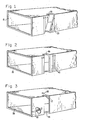
- FIG. 3 shows a particular device according to the present invention that solves most of the afore-mentioned problems.
- the waveguide 50 contains a non-inclined slot 55 in one of the narrow waveguide walls. Although the slot 55 extends partially into the broad walls of waveguide 50, this feature is not necessary to the operation of the invention.
- the slot 55 may be contained wholly within a narrow wall.
- the waveguide 50 also comprises two rods 60 and 65 disposed as shown inside the waveguide near the slot 55. One end of each rod is joined to the narrow waveguide wall adjacent slot 55. The other end of rod 60 is joined to the bottom waveguide wall and the other end of the rod 65 is joined to the top waveguide wall.
- Both rods 60 and 65 can be dip-soldered to the waveguide 50 at one time and are preferably made of aluminum.
- the aluminum waveguide is plated with tin or nickel in the areas where the rods are attached to the waveguide wall, so that the rods can be soldered to the wall.
- RF current is induced in the rods 60 and 65 by the electromagnetic field in the waveguide. These currents excite an electric field across the slot in the same manner that a two-wire transmission line would do so.
- the rods 60 and 65 can actually be considered as a two-wire transmission line feeding the slot. The energy radiated from the slot will have no undesirable cross-polarization because the slot is not inclined.
- FIGS. 4a-c show in more detail the orientation of rods 60 and 65 in one embodiment of the invention. According to this embodiment, an infinite variety of rod orientations is possible. Depending upon the application, a single rod, or more than two rods may be utilized. The rods may be curved or angled, and the rods' cross-section can be circular, triangular, square, or various other shapes. Both the waveguide and the rods can be made of aluminum or another suitable material.
- FIG. 5 illustrates another embodiment of this invention.
- the elliptical waveguide 70 contains a non-inclined curved slot 75 cut in its wall. Being cylindrical in shape, there is an imaginary generatrix associated with the waveguide 70. The longer edges of slot 75 are orthogonal to this generatrix.
- the rods 80 and 85 are mounted inside the waveguide, and one end of each of rods 80 and 85 is joined to the waveguide wall at a point adjacent the slot 75. The other end of each rod joins the waveguide 70 at a point away from the slot 75.
- the electromagnetic wave in the waveguide will induce current in the rods 80 and 85, which act as a two-wire transmission line that feeds the slot 75, causing an electric field across the slot 75. This electric field radiates energy into space without undesirable cross-polarized components.
- the power radiated from the slotted waveguide can be increased by increasing the area between one or more rods and the walls of the waveguide, or decreased by decreasing that area.
- power radiated from the slotted waveguide 50 could be increased or decreased by respectively increasing or decreasing either the dimension "x" of the rod 60, or the dimension "y", or both.
- An increase or decrease of either dimension would respectively increase or decrease the area between the rod 60 and the walls of the waveguide 50.
- the area between a rod and the waveguide walls could be increased by bending the rod away from the walls, or decreased by bending the rod toward the walls. The resulting increase or decrease of area would respectively increase or decrease the power radiated from the slotted waveguide.
Landscapes
- Waveguide Aerials (AREA)
- Control And Other Processes For Unpacking Of Materials (AREA)
- Burglar Alarm Systems (AREA)
- Radar Systems Or Details Thereof (AREA)
Applications Claiming Priority (2)
| Application Number | Priority Date | Filing Date | Title |
|---|---|---|---|
| US06/191,880 US4435715A (en) | 1980-09-29 | 1980-09-29 | Rod-excited waveguide slot antenna |
| US191880 | 1980-09-29 |
Publications (2)
| Publication Number | Publication Date |
|---|---|
| EP0048817A1 EP0048817A1 (en) | 1982-04-07 |
| EP0048817B1 true EP0048817B1 (en) | 1985-11-21 |
Family
ID=22707278
Family Applications (1)
| Application Number | Title | Priority Date | Filing Date |
|---|---|---|---|
| EP81106470A Expired EP0048817B1 (en) | 1980-09-29 | 1981-08-20 | Rod-excited waveguide slot antenna |
Country Status (6)
| Country | Link |
|---|---|
| US (1) | US4435715A (enExample) |
| EP (1) | EP0048817B1 (enExample) |
| KR (1) | KR880000165B1 (enExample) |
| DE (1) | DE3172990D1 (enExample) |
| GR (1) | GR74674B (enExample) |
| NO (1) | NO153198C (enExample) |
Families Citing this family (5)
| Publication number | Priority date | Publication date | Assignee | Title |
|---|---|---|---|---|
| DE3915048A1 (de) * | 1989-05-08 | 1990-11-15 | Siemens Ag | Elektronisch phasengesteuerte antennenanordnung |
| FR2654555B1 (fr) * | 1989-11-14 | 1992-06-19 | Thomson Csf | Guide a fentes rayonnantes non inclinees a excitation par motif rayonnant. |
| FR2685820B1 (fr) * | 1991-12-31 | 1994-03-18 | Thomson Csf | Guide a fentes rayonnantes non inclinees excitees par des volets metalliques. |
| DE102013012315B4 (de) * | 2013-07-25 | 2018-05-24 | Airbus Defence and Space GmbH | Hohlleiter-Strahler. Gruppenantennen-Strahler und Synthetik-Apertur-Radar-System |
| CN118435455A (zh) | 2021-12-23 | 2024-08-02 | 灏讯有限公司 | 天线装置 |
Family Cites Families (10)
| Publication number | Priority date | Publication date | Assignee | Title |
|---|---|---|---|---|
| US2574433A (en) | 1943-10-01 | 1951-11-06 | Roger E Clapp | System for directional interchange of energy between wave guides and free space |
| US2597144A (en) | 1945-09-14 | 1952-05-20 | Us Navy | Electromagnetic wave control structure |
| US2605411A (en) * | 1946-04-11 | 1952-07-29 | Henry J Riblet | Directional slot antenna |
| US3004259A (en) | 1958-07-21 | 1961-10-10 | Hughes Aircraft Co | Electrically variable waveguide slot with longitudinal polarization |
| GB889404A (en) * | 1958-07-21 | 1962-02-14 | Hughes Aircraft Co | Waveguide |
| US3183511A (en) | 1963-03-28 | 1965-05-11 | Hughes Aircraft Co | Broadband waveguide slot radiator with mutually coupled slots of different perimeters and orientation |
| US3176300A (en) | 1964-01-24 | 1965-03-30 | Avco Corp | Adjustable slotted wave guide radiator with coupling element |
| US3382501A (en) | 1965-09-22 | 1968-05-07 | Hughes Aircraft Co | Elliptically or circularly polarized antenna |
| US3604010A (en) * | 1969-01-30 | 1971-09-07 | Singer General Precision | Antenna array system for generating shaped beams for guidance during aircraft landing |
| US4303923A (en) | 1979-08-09 | 1981-12-01 | Motorola Inc. | Probe loop feed for transverse edge waveguide slot radiator |
-
1980
- 1980-09-29 US US06/191,880 patent/US4435715A/en not_active Expired - Lifetime
-
1981
- 1981-08-20 EP EP81106470A patent/EP0048817B1/en not_active Expired
- 1981-08-20 DE DE8181106470T patent/DE3172990D1/de not_active Expired
- 1981-08-21 GR GR65846A patent/GR74674B/el unknown
- 1981-09-17 NO NO81813167A patent/NO153198C/no unknown
- 1981-09-29 KR KR1019810003652A patent/KR880000165B1/ko not_active Expired
Also Published As
| Publication number | Publication date |
|---|---|
| EP0048817A1 (en) | 1982-04-07 |
| GR74674B (enExample) | 1984-07-02 |
| US4435715A (en) | 1984-03-06 |
| DE3172990D1 (en) | 1986-01-02 |
| KR830008422A (ko) | 1983-11-18 |
| NO813167L (no) | 1982-03-30 |
| NO153198B (no) | 1985-10-21 |
| NO153198C (no) | 1986-01-29 |
| KR880000165B1 (ko) | 1988-03-12 |
Similar Documents
| Publication | Publication Date | Title |
|---|---|---|
| EP0018476B1 (en) | Crossed slot cavity antenna | |
| Howell | Microstrip antennas | |
| US6680712B2 (en) | Antenna having a conductive case with an opening | |
| KR0182781B1 (ko) | 안테나장치 | |
| EP0410083A1 (en) | Annular slot antenna | |
| EP0891004A1 (en) | Omnidirectional slot antenna | |
| CN107134652A (zh) | 基于三角形基片集成波导谐振腔的圆极化缝隙天线 | |
| JPH0590833A (ja) | 翼板調整を行うスロツト放射器構造体 | |
| EP0048817B1 (en) | Rod-excited waveguide slot antenna | |
| US4507664A (en) | Dielectric image waveguide antenna array | |
| US6850205B2 (en) | Waveguide antenna apparatus provided with rectangular waveguide and array antenna apparatus employing the waveguide antenna apparatus | |
| WO1991005374A1 (en) | Monopole antenna | |
| US2946055A (en) | Parasitic dipole slot antenna | |
| CN109417223B (zh) | 圆极化双频天线 | |
| EP1393412A1 (en) | Ultra-wideband antennas | |
| EP0402005B1 (en) | Flush mount antenna | |
| EP1024549B1 (en) | Leaky wave antenna with grounding device | |
| RU2096871C1 (ru) | Логопериодическая резонаторная антенна | |
| CN216413268U (zh) | Mimo天线 | |
| KR100214579B1 (ko) | 마이크로스트립 안테나 | |
| KR100429410B1 (ko) | 접지면에 원형 슬롯을 갖는 마이크로스트립 스파이럴 안테나 | |
| RU2075803C1 (ru) | Логопериодическая резонаторная антенна | |
| WO1990007201A1 (en) | Improved feed waveguide for an array antenna | |
| JP2004336118A (ja) | アンテナ | |
| KR890009079Y1 (ko) | 마이크로 스트립형 수직편파 혼 안테나 |
Legal Events
| Date | Code | Title | Description |
|---|---|---|---|
| PUAI | Public reference made under article 153(3) epc to a published international application that has entered the european phase |
Free format text: ORIGINAL CODE: 0009012 |
|
| AK | Designated contracting states |
Designated state(s): DE NL |
|
| 17P | Request for examination filed |
Effective date: 19820925 |
|
| RAP1 | Party data changed (applicant data changed or rights of an application transferred) |
Owner name: HUGHES AIRCRAFT COMPANY |
|
| GRAA | (expected) grant |
Free format text: ORIGINAL CODE: 0009210 |
|
| AK | Designated contracting states |
Designated state(s): DE NL |
|
| REF | Corresponds to: |
Ref document number: 3172990 Country of ref document: DE Date of ref document: 19860102 |
|
| PLBE | No opposition filed within time limit |
Free format text: ORIGINAL CODE: 0009261 |
|
| STAA | Information on the status of an ep patent application or granted ep patent |
Free format text: STATUS: NO OPPOSITION FILED WITHIN TIME LIMIT |
|
| 26N | No opposition filed | ||
| PGFP | Annual fee paid to national office [announced via postgrant information from national office to epo] |
Ref country code: DE Payment date: 19940720 Year of fee payment: 14 |
|
| PGFP | Annual fee paid to national office [announced via postgrant information from national office to epo] |
Ref country code: NL Payment date: 19940831 Year of fee payment: 14 |
|
| PG25 | Lapsed in a contracting state [announced via postgrant information from national office to epo] |
Ref country code: NL Effective date: 19960301 |
|
| NLV4 | Nl: lapsed or anulled due to non-payment of the annual fee |
Effective date: 19960301 |
|
| PG25 | Lapsed in a contracting state [announced via postgrant information from national office to epo] |
Ref country code: DE Effective date: 19960501 |