EP0048654B1 - Dispositif de sécurité d'allumage des appareils de chauffage à gaz - Google Patents
Dispositif de sécurité d'allumage des appareils de chauffage à gaz Download PDFInfo
- Publication number
- EP0048654B1 EP0048654B1 EP19810401392 EP81401392A EP0048654B1 EP 0048654 B1 EP0048654 B1 EP 0048654B1 EP 19810401392 EP19810401392 EP 19810401392 EP 81401392 A EP81401392 A EP 81401392A EP 0048654 B1 EP0048654 B1 EP 0048654B1
- Authority
- EP
- European Patent Office
- Prior art keywords
- core
- intermediate element
- arms
- hand
- hooking
- Prior art date
- Legal status (The legal status is an assumption and is not a legal conclusion. Google has not performed a legal analysis and makes no representation as to the accuracy of the status listed.)
- Expired
Links
- 238000002788 crimping Methods 0.000 claims abstract description 4
- 238000010438 heat treatment Methods 0.000 claims abstract 2
- 238000004804 winding Methods 0.000 claims description 8
- 230000005284 excitation Effects 0.000 claims description 7
- 239000002184 metal Substances 0.000 claims description 7
- 230000000295 complement effect Effects 0.000 claims description 4
- 239000012777 electrically insulating material Substances 0.000 claims description 2
- 239000000463 material Substances 0.000 abstract description 2
- 230000001681 protective effect Effects 0.000 description 2
- 239000011324 bead Substances 0.000 description 1
- 239000004020 conductor Substances 0.000 description 1
- 238000010292 electrical insulation Methods 0.000 description 1
- 238000000034 method Methods 0.000 description 1
- 210000000056 organ Anatomy 0.000 description 1
- 238000005245 sintering Methods 0.000 description 1
- 238000003466 welding Methods 0.000 description 1
Images
Classifications
-
- F—MECHANICAL ENGINEERING; LIGHTING; HEATING; WEAPONS; BLASTING
- F23—COMBUSTION APPARATUS; COMBUSTION PROCESSES
- F23Q—IGNITION; EXTINGUISHING-DEVICES
- F23Q9/00—Pilot flame igniters
- F23Q9/08—Pilot flame igniters with interlock with main fuel supply
- F23Q9/12—Pilot flame igniters with interlock with main fuel supply to permit the supply to the main burner in dependence upon existence of pilot flame
- F23Q9/14—Pilot flame igniters with interlock with main fuel supply to permit the supply to the main burner in dependence upon existence of pilot flame using electric means, e.g. by light-sensitive elements
-
- F—MECHANICAL ENGINEERING; LIGHTING; HEATING; WEAPONS; BLASTING
- F23—COMBUSTION APPARATUS; COMBUSTION PROCESSES
- F23N—REGULATING OR CONTROLLING COMBUSTION
- F23N5/00—Systems for controlling combustion
- F23N5/02—Systems for controlling combustion using devices responsive to thermal changes or to thermal expansion of a medium
- F23N5/10—Systems for controlling combustion using devices responsive to thermal changes or to thermal expansion of a medium using thermocouples
- F23N5/107—Systems for controlling combustion using devices responsive to thermal changes or to thermal expansion of a medium using thermocouples using mechanical means, e.g. safety valves
-
- Y—GENERAL TAGGING OF NEW TECHNOLOGICAL DEVELOPMENTS; GENERAL TAGGING OF CROSS-SECTIONAL TECHNOLOGIES SPANNING OVER SEVERAL SECTIONS OF THE IPC; TECHNICAL SUBJECTS COVERED BY FORMER USPC CROSS-REFERENCE ART COLLECTIONS [XRACs] AND DIGESTS
- Y10—TECHNICAL SUBJECTS COVERED BY FORMER USPC
- Y10T—TECHNICAL SUBJECTS COVERED BY FORMER US CLASSIFICATION
- Y10T137/00—Fluid handling
- Y10T137/1407—Combustion failure responsive fuel safety cut-off for burners
- Y10T137/1516—Thermo-electric
Definitions
- Security devices have already been proposed, in particular by patents FR-A-1 598837, FR-A-2177416 and FR-A-2435001. Such devices include a valve located on a gas supply pipe.
- a device for detecting the proper functioning of the device for example a thermocouple, delivers an electric current ensuring the excitation of an electromagnet constituting a control of the valve and keeping it in its open position against the action of a spring.
- valve control electromagnet is mounted on a metal support which on the one hand is electrically connected to ground as well as to one of the ends of the excitation winding.
- This support also receives a metal tip which is electrically connected to the other end of the winding and which constitutes a connection element for the electrical conductor coming from the burner operating detector.
- Magnetic head An assembly which is all the more delicate as one generally imposes on manufacturers very small maximum dimensions for the whole of the safety device, referred to below. "Magnetic head”.
- the invention due in particular to the work of the Technical Center for the Watch Industry therefore relates to a magnetic head of the type briefly described above, providing a safe and economically advantageous solution to the requirements mentioned above.
- an intermediate element of electrically insulating and elastically deformable material, having on the one hand at least one substantially cylindrical portion extending between the cylindrical zones opposite the support and the end piece, which is fixed on the intermediate element by crimping one of its ends, on the other hand a plurality of branches extending longitudinally and forming a housing for the core of the electromagnet, at least some of them being provided with attachment cooperating with the core to secure it.
- the magnetic head essentially comprises a support 1 constituted by a thick metal ring having a cylindrical bore la, on which are successively mounted on the one hand an intermediate element 2 linked to the core 3 d 'an electromagnet, on the other hand a metal tip 4 constituting an electrical connection member.
- the valve 8 of a valve At the free end of the push rod 6 is subject the valve 8 of a valve, the seat 9 of which is incorporated in a gas supply duct 10 shown diagrammatically.
- a spring 11 is supported on the valve 8 which it thus maintains applied against the seat 9 in the absence of any force in the opposite direction exerted by the electromagnet on the plate 5. It will however be noted that after mounting of the magnetic head in the duct 10 the plate 5 occupies the position shown in dotted line in FIG. 1.
- the intermediate element 2 is made of elastically deformable and electrically insulating material, preferably of plastic. It has at its right end ( Figure 1) a cylindrical portion 2a interposed between the internal face of the bore 1a of the support and the cylindrical external face 4a of the connection end piece.
- the intermediate element also has a central bore comprising a shoulder 2b in the form of a bowl. The left end of the endpiece 4 is pushed back by crimping, partial or total, until it comes to bear on the shoulder 2b, after an electrically insulating washer 12 has been interposed between the support 1 and the endpiece 4
- the support 1, the intermediate element 2 and the end piece 4 then constitute a one-piece assembly.
- the intermediate element 2 comprises, on the one hand, two branches 13 and 14 extending longitudinally and diametrically opposite, on the other hand four branches 15, 16, 17 and 18, preferably more shorter than the previous ones and symmetrical two by two with respect to the diametral plane defined by the first two.
- the four branches 15, 16, 17, 18 have a boss 15a, 16a, 17a, 18a constituting a hooking member of the core 3 of the electromagnet under conditions which will be specified.
- the number of branches is not limited by the invention, their assembly forming a housing in which the core will be secured to the intermediate element 2.
- the core 3 of the electromagnet is a U-shaped part, with a thick base 3a and with relatively short branches 3b.
- An excitation winding 19 shown schematically in Figure 3 is arranged around the base of the core between its two branches.
- the base 3a of the core has reliefs 20, 21, 22, 23 or other attachment members complementary to those provided in correspondence on the branches 15, 16, 17, 18 of the intermediate element 2.
- the core can be produced by any suitable method, in particular by sintering. After having received its excitation winding, it is mounted on the support 1 by introduction of the two branches of the U between the two branches 13 and 14 of the intermediate element 2 which guide it thanks to their complementary shapes, visible in particular on the Figure 2.
- the reliefs 20, 21, 22 and 23 of its base meet the bosses 15a, 16a, 17a, 18a which are first pushed outwards thanks to the elasticity of the branches which carry them and which then lock behind the bosses, thus ensuring the fixing of the core and more generally of the electromagnet.
- One end 19a of the excitation winding is fixed, for example by welding, in a housing provided for this purpose in the support, while the other end 19b is fixed to the connection piece 4.
- a bead 7b engages elastically in a groove 2c formed at the external periphery of the intermediate element 2.
- the magnetic head thus completed is disposed in the supply line 10 electrically connected to ground and is subject thereto by any suitable means.
- the connection end piece 4 is connected to one of the terminals of the operating detector, the other terminal of which is connected to ground, thus closing the electrical circuit of the electromagnet.
- the detector When the gas appliance operates normally, the detector produces an electric current, so that the magnetic field created attracts the plate 5 from its position in dotted line (FIG. 1) until contact with the ends of the branches of the core 3.
- the valve 8 is thus kept away from its seat against the action of the spring 11 and allows the passage of gas.
- the detector In the event of failure of the appliance or of its gas supply, the detector no longer generates electric current and the valve closes automatically under the action of the spring.
- the invention is not limited to the embodiment which has just been described but on the contrary covers all the variants thereof, in particular as regards the number and the arrangement of the branches of the intermediate element as well as their organs attachment provided in correspondence with those of the core.
Landscapes
- Engineering & Computer Science (AREA)
- Chemical & Material Sciences (AREA)
- Combustion & Propulsion (AREA)
- Mechanical Engineering (AREA)
- General Engineering & Computer Science (AREA)
- Control Of Combustion (AREA)
- Magnetically Actuated Valves (AREA)
- Feeding And Controlling Fuel (AREA)
- Air Bags (AREA)
Description
- On sait que la réglementation de sécurité des appareils de chauffage à gaz exige une fermeture automatique de l'alimentation en gaz chaque fois qu'un brûleur s'éteint pour une cause accidentelle. Des dispositifs de sécurité ont déjà été proposés, notamment par les brevets FR-A-1 598837, FR-A-2177416 et FR-A-2435001. De tels dispositifs, comportent une valve située sur une canalisation d'alimentation en gaz. Un organe de détection du bon fonctionnement de l'appareil, par exemple un thermocouple, délivre un courant électrique assurant l'excitation d'un électroaimant constituant une commande de la valve et la maintenant dans sa position ouverte à l'encontre de l'action d'un ressort.
- En général, l'électro-aimant de commande de la valve est monté sur un support métallique qui d'une part est relié électriquement à la masse ainsi qu'à l'une des extrémités de l'enroulement d'excitation. Ce support reçoit d'autre part un embout métallique qui est relié électriquement à l'autre extrémité de l'enroulement et qui constitue un élément de connexion pour le conducteur électrique provenant du détecteur de fonctionnement du brûleur.
- Il est évidemment essentiel qu'un bon isolement électrique soit assuré entre le support de l'électro-aimant et l'embout de connexion, cependant que l'électro-aimant, et plus particulièrement son noyau, doivent être fermement assujettis au support.
- Les solutions techniques apportées jusqu'à présent pour satisfaire à cette double exigence entraînent un montage d'autant plus délicat que l'on impose en général aux constructeurs des dimensions maximales très faibles pour l'ensemble du dispositif de sécurité, dénommé dans ce qui suit «tête magnétique».
- L'invention due notamment aux travaux du Centre Technique de l'Industrie horlogère a donc pour objet une tête magnétique du type sommairement décrit ci-dessus, apportant une solution sûre et économiquement intéressante aux exigences mentionnées plus haut.
- Elle prévoit un élément intermédiaire, en matière électriquement isolante et élastiquement déformable, présentant d'une part au moins une portion sensiblement cylindrique s'étendant entre les zones cylindriques en regard du support et de l'embout, lequel est fixé sur l'élément intermédiaire par sertissage de l'une de ses extrémités, d'autre part une pluralité de branches s'étendant longitudinalement et formant un logement pour le noyau de l'électro-aimant, certaines au moins d'entre elles étant munies d'organes d'accrochage coopérant avec le noyau pour assurer sa fixation.
- L'invention sera mieux comprise et certaines de ses dispositions secondaires et avantageuses apparaîtront au cours de la description qui va suivre, d'un mode de réalisation donné uniquement à titre d'exemple. A cet effet on se référera aux dessins - annexés dans lesquels:
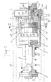
- - la figure 1 est une vue extérieure longitudinale d'une tête magnétique selon l'invention avec arrachement et coupe partielle par un plan diamétral;
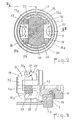
- - la figure 2 est une coupe selon II-II de la figure 1;
- - la figure 3 est une coupe partielle selon III-III de la figure 2.
- Si l'on se reporte au dessin, on voit que la tête magnétique comporte essentiellement un support 1 constitué par un anneau métallique épais présentant un alésage cylindrique la, sur lequel sont successivement montés d'une part un élément intermédiaire 2 lié au noyau 3 d'un électroaimant, d'autre part un embout métallique 4 constituant un organe de connexion électrique.
- Une plaque mobile 5, attelée à une tige-poussoir 6 montée coulissante dans un manchon 7a faisant partie d'un capot protecteur 7, estsuscep- tible d'être attirée vers le noyau 3 lorsque l'enroulement 19 de l'électro-aimant est parcouru par un courant électrique. A l'extrémité libre de la tige-poussoir 6 est assujetti le clapet 8 d'une valve, dont le siège 9 est incorporé dans un conduit d'alimentation en gaz 10 représenté schématiquement. Un ressort 11 prend appui sur le clapet 8 qu'il maintient ainsi appliqué contre le siège 9 en l'absence de tout effort en sens contraire exercé par l'électro-aimant sur la plaque 5. On notera cependant qu'après montage de la tête magnétique dans le conduit 10 la plaque 5 occupe la position représentée en trait ponctué sur la figure 1.
- L'élément intermédiaire 2 est en matériau élastiquement déformable et électriquement isolant, de préférence en matière plastique. Il possède à son extrémité droite (figure 1) une portion cylindrique 2a s'interposant entre la face interne de l'alésage 1a du support et la face externe cylindrique 4a de l'embout de connexion. L'élément intermédiaire présente d'autre part un alésage central comportant un épaulement 2b en forme de cuvette. L'extrémité gauche de l'embout 4 est repoussé par sertissage, partiel ou total, jusqu'à venir en appui sur l'épaulement 2b, après qu'une rondelle électriquement isolante 12 a été interposée entre le support 1 et l'embout 4. Le support 1, l'élément intermédiaire 2 et l'embout 4 constituent alors un ensemble monobloc.
- A son extrémité gauche (figure 1) l'élément intermédiaire 2 comporte, d'une part, deux branches 13 et 14 s'étendant longitudinalement et diamétralement opposées, d'autre part quatre branches 15, 16, 17 et 18, de préférence plus courtes que les précédentes et symétriques deux à deux par rapport au plan diamétral défini par les deux premières. A leur extrémité libre les quatre branches 15, 16, 17, 18 présentent un bossage 15a, 16a, 17a, 18a constituant un organe d'accrochage du noyau 3 de l'électro-aimant dans des conditions que l'on va préciser. Bien entendu le nombre de branches n'est pas limité par l'invention, leur ensemble formant un logement dans lequel le noyau sera assujetti à l'élément intermédiaire 2.
- Le noyau 3 de l'électro-aimant est une pièce en forme de U, à base 3a épaisse et à branches 3b relativement courtes. Un enroulement d'excitation 19 représenté schématiquement sur la figure 3 est disposé autour de la base du noyau entre ses deux branches.
- La base 3a du noyau présente des reliefs 20, 21, 22, 23 ou autres organes d'accrochage complémentaires de ceux prévus en correspondance sur les branches 15, 16, 17, 18 de l'élément intermédiaire 2.
- Le noyau peut être réalisé par tout procédé approprié, notamment par frittage. Après avoir reçu son enroulement d'excitation, il est monté sur le support 1 par introduction des deux branches du U entre les deux branches 13 et 14 de l'élément intermédiaire 2 qui assurent son guidage grâce à leurs formes complémentaires, visibles notamment sur la figure 2. Au cours de l'enfoncement du noyau, les reliefs 20, 21, 22 et 23 de sa base rencontrent les bossages 15a, 16a, 17a, 18a qui sont d'abord repoussés vers l'extérieur grâce à l'élasticité des branches qui les portent et qui viennent ensuite se verrouiller derrière les bossages, assurant ainsi la fixation de noyau et plus généralement de l'électro-aimant.
- L'une des extrémités 19a de l'enroulement d'excitation est fixée, par soudage par exemple, dans un logement prévu à cet effet dans le support, cependant que l'autre extrémité 19b est fixée à l'embout 4 de connexion.
- Le capot protecteur 7, ayant reçu au préalable l'équipage mobile, est alors introduit autour de l'élément intermédiaire 2. Il présente un diamètre intérieur voisin du diamètre extérieur des branches de l'élément 2 dont le verrouillage sur le noyau est ainsi renforcé. A son extrémité ouverte un bourrelet 7b s'engage élastiquement dans une rainure 2c ménagée à la périphérie externe de l'élément intermédiaire 2.
- La tête magnétique ainsi terminée est disposée dans la canalisation d'alimentation 10 reliée électriquement à la masse et y est assujettie par tout moyen approprié. L'embout de connexion 4 est relié à l'une des bornes du détecteur de fonctionnement dont l'autre borne est reliée à la masse, fermant ainsi le circuit électrique de l'électroaimant.
- Lorsque l'appareil à gaz fonctionne normalement, le détecteur produit un courant électrique, de sorte que le champ magnétique créé attire la plaque 5 depuis sa position en trait ponctué (figure 1) jusqu'au contact avec les extrémités des branches du noyau 3. Le clapet 8 est ainsi maintenu éloigné de son siège contre l'action du ressort 11 et autorise le passage du gaz. En cas de défaillance de l'appareil ou de son alimentation en gaz, le détecteur n'engendre plus de courant électrique et le clapet se ferme automatiquement sous l'action du ressort.
- Bien entendu l'invention n'est pas limitée au mode de réalisation qui vient d'être décrit mais en couvre au contraire toutes les variantes, notamment en ce qui concerne le nombre et la disposition des branches de l'élément intermédiaire ainsi que leurs organes d'accrochage prévus en correspondance avec ceux du noyau.
Claims (4)
Priority Applications (1)
| Application Number | Priority Date | Filing Date | Title |
|---|---|---|---|
| AT81401392T ATE6303T1 (de) | 1980-09-17 | 1981-09-07 | Zuendsicherungsvorrichtung fuer gasgeraete. |
Applications Claiming Priority (2)
| Application Number | Priority Date | Filing Date | Title |
|---|---|---|---|
| FR8020032A FR2490323A1 (fr) | 1980-09-17 | 1980-09-17 | Dispositif de securite d'allumage des appareils de chauffage a gaz |
| FR8020032 | 1980-09-17 |
Publications (2)
| Publication Number | Publication Date |
|---|---|
| EP0048654A1 EP0048654A1 (fr) | 1982-03-31 |
| EP0048654B1 true EP0048654B1 (fr) | 1984-02-15 |
Family
ID=9246030
Family Applications (1)
| Application Number | Title | Priority Date | Filing Date |
|---|---|---|---|
| EP19810401392 Expired EP0048654B1 (fr) | 1980-09-17 | 1981-09-07 | Dispositif de sécurité d'allumage des appareils de chauffage à gaz |
Country Status (8)
| Country | Link |
|---|---|
| US (1) | US4429706A (fr) |
| EP (1) | EP0048654B1 (fr) |
| JP (1) | JPS57120025A (fr) |
| AT (1) | ATE6303T1 (fr) |
| BR (1) | BR8105853A (fr) |
| DE (1) | DE3162306D1 (fr) |
| ES (1) | ES8206810A1 (fr) |
| FR (1) | FR2490323A1 (fr) |
Families Citing this family (4)
| Publication number | Priority date | Publication date | Assignee | Title |
|---|---|---|---|---|
| GB2249383B (en) * | 1990-10-31 | 1995-02-08 | Union Gas Appliances Trading L | Gas cooker |
| AU2001252780A1 (en) * | 2000-04-10 | 2001-10-23 | Fisher & Paykel Appliances Limited | Gas heating appliance |
| JP4717034B2 (ja) * | 2007-07-06 | 2011-07-06 | リンナイ株式会社 | 電磁安全弁 |
| FR2947321A1 (fr) * | 2009-06-26 | 2010-12-31 | Schrader Sas | Valve integrant un capteur |
Family Cites Families (8)
| Publication number | Priority date | Publication date | Assignee | Title |
|---|---|---|---|---|
| DE1601964U (de) | 1949-12-27 | 1950-02-23 | Gustav A Dipl Ing Emmerling | Abstellplatte fuer rundfunkempfaenger. |
| US2763277A (en) | 1951-08-10 | 1956-09-18 | Milwaukee Gas Specialty Co | Combined permanent magnet and electromagnet assembly for thermoelectric safety devices |
| DE1778246A1 (de) | 1968-01-19 | 1971-09-02 | It Tecnomeccanica La Precisa S | Sicherheitselektroventil an Gasbrennern |
| DE1601964A1 (de) * | 1968-03-13 | 1971-03-18 | Junkers & Co | Magneteinsatz fuer eine thermoelektrische Zuendsicherungsvorrichtung |
| US3581753A (en) | 1969-10-14 | 1971-06-01 | Honeywell Inc | Limit switch connector |
| US3821675A (en) | 1972-03-23 | 1974-06-28 | Vaillant Joh Kg | Solenoid assembly and thermoelectric flame failure device |
| US3998425A (en) | 1975-05-22 | 1976-12-21 | Robertshaw Controls Company | Electromagnet assembly for safety valve |
| DE2837966A1 (de) | 1978-08-31 | 1980-03-20 | Bosch Gmbh Robert | Magneteinsatz fuer eine thermoelektrische zuendsicherung |
-
1980
- 1980-09-17 FR FR8020032A patent/FR2490323A1/fr active Granted
-
1981
- 1981-08-20 US US06/294,433 patent/US4429706A/en not_active Expired - Fee Related
- 1981-09-03 JP JP13787181A patent/JPS57120025A/ja active Granted
- 1981-09-07 EP EP19810401392 patent/EP0048654B1/fr not_active Expired
- 1981-09-07 DE DE8181401392T patent/DE3162306D1/de not_active Expired
- 1981-09-07 AT AT81401392T patent/ATE6303T1/de not_active IP Right Cessation
- 1981-09-14 BR BR8105853A patent/BR8105853A/pt unknown
- 1981-09-17 ES ES505584A patent/ES8206810A1/es not_active Expired
Also Published As
| Publication number | Publication date |
|---|---|
| JPH0158414B2 (fr) | 1989-12-12 |
| EP0048654A1 (fr) | 1982-03-31 |
| FR2490323B1 (fr) | 1984-11-16 |
| ATE6303T1 (de) | 1984-03-15 |
| BR8105853A (pt) | 1982-06-08 |
| FR2490323A1 (fr) | 1982-03-19 |
| US4429706A (en) | 1984-02-07 |
| ES505584A0 (es) | 1982-08-16 |
| JPS57120025A (en) | 1982-07-26 |
| DE3162306D1 (en) | 1984-03-22 |
| ES8206810A1 (es) | 1982-08-16 |
Similar Documents
| Publication | Publication Date | Title |
|---|---|---|
| FR2569337A1 (fr) | Construction d'une fixation liberable utilisable notamment dans le domaine des bijoux personnels | |
| EP1610045B1 (fr) | Electrovanne, en particulier pour être installée sur un reservoir de liquide sous pression de gaz | |
| EP0828275A1 (fr) | Contacteur de démarreur comportant un circuit électronique de commande intégré au contacteur, et démarreur de véhicule comportant un tel contacteur | |
| FR2582599A1 (fr) | Allume-cigares pour vehicule automobile | |
| FR2735187A1 (fr) | Poussoir a actionnement unique motorise par un materiau a memoire de forme. | |
| EP0048654A1 (fr) | Dispositif de sécurité d'allumage des appareils de chauffage à gaz | |
| FR2744962A1 (fr) | Allume-cigares a dispositif de protection, notamment pour vehicule automobile | |
| EP0758961B1 (fr) | Corps d'allumage pour allume-cigares, notamment de vehicule automobile | |
| FR2472516A1 (fr) | Bouchon d'une seule piece en matiere plastique | |
| FR2518829A1 (fr) | Contact a broche electrique active | |
| FR2523366A1 (fr) | Support de fusible | |
| FR2797720A1 (fr) | Dispositif de distribution de courant commande a verrouillage mecanique de la fiche dans un socle correspondant | |
| CH650320A5 (en) | Solenoid valve | |
| EP1139060A1 (fr) | Initiateur pyrotechnique pouvant être équipé d'un composant électrique ou électronique et/ou d'un connecteur | |
| EP0462900B1 (fr) | Corps d'allumage pour allume-cigares, notamment pour véhicules automobiles et ensemble corps d'allumage-bague éclairante comportant un tel corps d'allumage | |
| EP1925011B1 (fr) | Contacteur de demarreur de moteur thermique comportant des moyens perfectionnes de raccordement electrique de son bobinage | |
| FR2675958A1 (fr) | Dispositif de securite pour le branchement et le retrait d'une lampe a incandescence a culots lateraux. | |
| EP1650780A1 (fr) | Déclencheur électromagnétique et appareil de protection électronique le comportant | |
| FR2724610A1 (fr) | Corps d'allumage pour allume-cigares, notamment pour vehicules automobiles | |
| EP2858085B1 (fr) | Capot de contacteur électromagnétique de démarreur de véhicule automobile, contacteur électromagnétique et démarreur correspondants | |
| FR2584476A1 (fr) | Raccord de conduit | |
| EP0268502B1 (fr) | Couvercle de distributeur d'allumage comportant au moins un embout pour câble en forme d'agrafe | |
| FR2786572A1 (fr) | Dispositif de detection de la presence d'une piece sur une structure de support | |
| EP1501112B1 (fr) | Sous-ensemble magnétique amélioré et disjoncteur comportant un tel sous-ensemble magnétique | |
| FR2482264A3 (fr) | Dispositif de protection contre le gaz, notamment pour des fours et des chaudieres a gaz |
Legal Events
| Date | Code | Title | Description |
|---|---|---|---|
| PUAI | Public reference made under article 153(3) epc to a published international application that has entered the european phase |
Free format text: ORIGINAL CODE: 0009012 |
|
| AK | Designated contracting states |
Designated state(s): AT BE CH DE FR GB IT LI LU NL SE |
|
| 17P | Request for examination filed |
Effective date: 19820304 |
|
| RAP1 | Party data changed (applicant data changed or rights of an application transferred) |
Owner name: MADEC MATER |
|
| ITF | It: translation for a ep patent filed | ||
| GRAA | (expected) grant |
Free format text: ORIGINAL CODE: 0009210 |
|
| AK | Designated contracting states |
Designated state(s): AT BE CH DE FR GB IT LI LU NL SE |
|
| REF | Corresponds to: |
Ref document number: 6303 Country of ref document: AT Date of ref document: 19840315 Kind code of ref document: T |
|
| REF | Corresponds to: |
Ref document number: 3162306 Country of ref document: DE Date of ref document: 19840322 |
|
| PLBE | No opposition filed within time limit |
Free format text: ORIGINAL CODE: 0009261 |
|
| STAA | Information on the status of an ep patent application or granted ep patent |
Free format text: STATUS: NO OPPOSITION FILED WITHIN TIME LIMIT |
|
| 26N | No opposition filed | ||
| PGFP | Annual fee paid to national office [announced via postgrant information from national office to epo] |
Ref country code: AT Payment date: 19920824 Year of fee payment: 12 |
|
| PGFP | Annual fee paid to national office [announced via postgrant information from national office to epo] |
Ref country code: GB Payment date: 19920901 Year of fee payment: 12 |
|
| PGFP | Annual fee paid to national office [announced via postgrant information from national office to epo] |
Ref country code: CH Payment date: 19920914 Year of fee payment: 12 |
|
| PGFP | Annual fee paid to national office [announced via postgrant information from national office to epo] |
Ref country code: LU Payment date: 19920921 Year of fee payment: 12 |
|
| PGFP | Annual fee paid to national office [announced via postgrant information from national office to epo] |
Ref country code: DE Payment date: 19920923 Year of fee payment: 12 |
|
| PGFP | Annual fee paid to national office [announced via postgrant information from national office to epo] |
Ref country code: SE Payment date: 19920929 Year of fee payment: 12 Ref country code: FR Payment date: 19920929 Year of fee payment: 12 |
|
| ITTA | It: last paid annual fee | ||
| PGFP | Annual fee paid to national office [announced via postgrant information from national office to epo] |
Ref country code: NL Payment date: 19920930 Year of fee payment: 12 |
|
| PGFP | Annual fee paid to national office [announced via postgrant information from national office to epo] |
Ref country code: BE Payment date: 19921013 Year of fee payment: 12 |
|
| EPTA | Lu: last paid annual fee | ||
| PG25 | Lapsed in a contracting state [announced via postgrant information from national office to epo] |
Ref country code: LU Free format text: LAPSE BECAUSE OF NON-PAYMENT OF DUE FEES Effective date: 19930907 Ref country code: GB Effective date: 19930907 Ref country code: AT Effective date: 19930907 |
|
| PG25 | Lapsed in a contracting state [announced via postgrant information from national office to epo] |
Ref country code: SE Effective date: 19930908 |
|
| PG25 | Lapsed in a contracting state [announced via postgrant information from national office to epo] |
Ref country code: LI Effective date: 19930930 Ref country code: CH Effective date: 19930930 Ref country code: BE Effective date: 19930930 |
|
| BERE | Be: lapsed |
Owner name: MADEC MATER Effective date: 19930930 |
|
| PG25 | Lapsed in a contracting state [announced via postgrant information from national office to epo] |
Ref country code: NL Effective date: 19940401 |
|
| GBPC | Gb: european patent ceased through non-payment of renewal fee |
Effective date: 19930907 |
|
| NLV4 | Nl: lapsed or anulled due to non-payment of the annual fee | ||
| PG25 | Lapsed in a contracting state [announced via postgrant information from national office to epo] |
Ref country code: FR Free format text: LAPSE BECAUSE OF NON-PAYMENT OF DUE FEES Effective date: 19940531 |
|
| REG | Reference to a national code |
Ref country code: CH Ref legal event code: PL |
|
| PG25 | Lapsed in a contracting state [announced via postgrant information from national office to epo] |
Ref country code: DE Effective date: 19940601 |
|
| REG | Reference to a national code |
Ref country code: FR Ref legal event code: ST |
|
| EUG | Se: european patent has lapsed |
Ref document number: 81401392.6 Effective date: 19940410 |