EP0048575A1 - Overhead electric and optical transmission system - Google Patents
Overhead electric and optical transmission system Download PDFInfo
- Publication number
- EP0048575A1 EP0048575A1 EP81304171A EP81304171A EP0048575A1 EP 0048575 A1 EP0048575 A1 EP 0048575A1 EP 81304171 A EP81304171 A EP 81304171A EP 81304171 A EP81304171 A EP 81304171A EP 0048575 A1 EP0048575 A1 EP 0048575A1
- Authority
- EP
- European Patent Office
- Prior art keywords
- optical
- joint
- housing
- optical guide
- overhead electric
- Prior art date
- Legal status (The legal status is an assumption and is not a legal conclusion. Google has not performed a legal analysis and makes no representation as to the accuracy of the status listed.)
- Granted
Links
Images

Classifications
-
- G—PHYSICS
- G02—OPTICS
- G02B—OPTICAL ELEMENTS, SYSTEMS OR APPARATUS
- G02B6/00—Light guides; Structural details of arrangements comprising light guides and other optical elements, e.g. couplings
- G02B6/44—Mechanical structures for providing tensile strength and external protection for fibres, e.g. optical transmission cables
- G02B6/4401—Optical cables
- G02B6/4415—Cables for special applications
- G02B6/4416—Heterogeneous cables
- G02B6/4417—High voltage aspects, e.g. in cladding
- G02B6/442—Insulators
Definitions
- optical bundle is meant a group of optical fibres or a group of fibres including at least one optical fibre and at least one non-optical reinforcing fibre or other reinforcing elongate member.
- Each optical fibre of the optical bundle may be used independently as a separate light guide, each with its own modulated light source and detector, or a plurality of optical fibres of a bundle may be used together as a single light guide, with a single light source.
- the optical guides connected at the joint may be optical guides of two overhead electric conductors suspended from a tower or other support, or one of the optical guides may be an optical guide of an overhead electric conductor suspended from a tower or other support and the other of the optical guides may be an optical guide of a cable extending to a sub-station or other location.
Abstract
Description
- This invention relates to overhead electric transmission systems of the kind in which one or more than one overhead electric conductor is freely supported in long lengths between spaced pylons, towers, masts or other supports. The invention is particularly concerned with overhead electric transmission systems of this kind in which the overhead electric conductor, or at least one of the overhead electric conductors, includes at least one optical guide for the transmission of the ultra-violet, visible and infra-red regions of the electromagnetic spectrum, which regions, for convenience, hereinafter will all be included in the generic term "light".
- One form of overhead electric conductor including at least one optical guide for use in the communications field adapted for transmission of light having a wavelength within the range 0.8 to 1.3 micrometres, is described and claimed in the Complete Specification of our cognate UK Patent Applications Nos. 20234/77 and 2861/78 (Serial No.1598438) and comprises at least one layer of helically wound bare elongate elements of metal or metal alloy, at least one compartment within and extending throughout the length of the overhead conductor and, loosely housed in the elongate comparment or in an least one of the elongate compartments, at least one separate optical fibre and/or at least one optical bundle.
- By the expression "optical bundle" is meant a group of optical fibres or a group of fibres including at least one optical fibre and at least one non-optical reinforcing fibre or other reinforcing elongate member. Each optical fibre of the optical bundle may be used independently as a separate light guide, each with its own modulated light source and detector, or a plurality of optical fibres of a bundle may be used together as a single light guide, with a single light source.
- It will be appreciated that, in an overhead electric transmission system of the aforesaid kind in which the overhead electric conductor, or at least one of the overhead electric conductors, includes at least one optical guide for the transmission of light, it is necessary at spaced positions along the overhead electric transmission system to effect a joint between the optical guides of two overhead electric conductors suspended from a tower or other support or to effect a joint between the optical guide of an overhead electric conductor suspended from a tower or other support and an optical guide of a cable extending to a sub-station or other location.
- According to the present invention we provide, in an overhead electric transmission system of the aforesaid kind in which the overhead electric conductor, or at least one of the overhead electric conductors, includes one or more than one optical guide comprising at least one optical fibre for the transmission of light, an optical guide joint in which each optical guide connected at the joint passes into a housing which is directly or indirectly mounted above the ground on a tower or other support, which accommodates the optical fibre joint or joints and which is at least partially filled with an electrically insulating medium in a fluid or semi-fluid state to an extent sufficient to surround the optical fibre joint or joints, each optical guide effecting a substantially fluid-tight seal with a wall of the housing or entering the housing in such a way that risk of water or other liquid entering the housing is substantially eliminated.
- The optical guides connected at the joint may be optical guides of two overhead electric conductors suspended from a tower or other support, or one of the optical guides may be an optical guide of an overhead electric conductor suspended from a tower or other support and the other of the optical guides may be an optical guide of a cable extending to a sub-station or other location.
- Preferably, where one or each optical guide connected at the joint is a component part of a live overhead electric conductor, the wall of the housing through which the optical guide or guides passes or pass is of electrically conductive metal or metal alloy and, preferably also, the internal surface of the housing in at least the vicinity of said wall carries a layer of electrically conductive metal or metal alloy so as to reduce electric stress concentration in that part of the housing. To eliminate risk that rain water or other liquid will enter the housing where the optical guide of an overhead electric conductor passes through the wall of the housing, preferably the optical guide enters the housing through a preformed tube of metal or metal alloy, one end of which is a substantially fluid-tight seal in a hole in said wall of the housing and which is of such a shape that the other end of the tube is directed downwardly; the overhead electric conductor may itself pass through the preformed tube into the housing or the overhead electric conductor may be cut back and the exposed length of optical guide may pass through the preformed tube into the housing. The end of the tube sealed in the wall of the housing may protrude into the housing and may be so shaped as to form a stress cone.
- Preferably, the housing is of substantially elongate form and is preferably so mounted that its longitudinal axis is vertical or approximately vertical. Where the optical guides connected at the joint are optical guides of two overhead electric conductors, preferably the optical guides enter the housing side by side through the upper end wall of the housing. Where one of the optical guides connected at the joint is the optical guide of a cable extending to a sub-station or other location, this optical guide preferably passes into the housing through the bottom end wall of the housing. In this case, preferably the bottom end wall of the housing is of electrically conductive metal or metal alloy and is earthed. The circumferentially extending wall of the housing is preferably of porcelain or other electrically insulating material and may be provided at spaced positions along its length with outwardly extending circumferential sheds.
- The electrically insulating medium contained in the housing preferably comprises a grease-like material, such as a petroleum-based insulating grease, a mineral insulating oil, such as an oil used in transformers and oil-filled electric cables, a silicone oil or compound, or an insulating gas, eg. SF6. Where the electrically insulating medium is a mineral insulating oil, a silicone oil or compound or an insulating gas, each optical guide may effect a substantially fluid-tight seal with a wall of the housing and the oil or gas may be maintained at a positive pressure by a known device. The or each optical fibre joint may be suspended within the housing and, in this case, abutting end of opticl fibres are preferably jointed by a fusion technique. Alternatively, the or each optical fibre joint may be rigidly supported within the housing and, in this case, abutting ends of optical fibres may be either be jointed by a fusion technique or held in abutting relationship by mechanical means.
- In addition to the optical fibre joint or joints, the housing of the optical guide joint may also accommodate regenerators and/or other ancillary equipment associated with the optical communication system.
- The invention is further illustrated, by way of example, by the following descripton with reference to drawings, in which:-
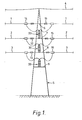
- Figure 1 is a diagrammatic side view of a tower of an overhead electric transmission system showing mounted on the tower, the housings of three optical guide joints between overhead electric conductors suspended from the tower;
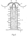
- Figure 2 is a diagrammatic sectional side view of a preferred optical guide joint between optical guides of two overhead electric conductors suspended from the tower shown in Figure 1, and
- Figure 3 is a diagrammatic side view of a preferred optical guide joint between an optical guide of a live overhead electric conductor suspended from a tower and the optical guide of an optical cable extending to a sub-station.
- Referring to Figures 1 and 2, the overhead electric transmission system comprises three
phase conductors towers 5 at spaced positions along the system. Eachphase conductor optical guide 18 comprising an elongate plastics body having a bore in which is loosely housed an optical fibre.Phase conductors 1 on opposite sides of atower 5 are freely suspended from across-arm 6 on the tower byinsulator strings 11 which are connected to the conductors by conventional wedge-type fittings 14;phase conductors 2 on opposite sides of the tower are freely suspended from across-arm 7 byinsulator strings 12 connected to the conductors by wedge-type fittings 15; andphase conductors 3 on opposite sides of the tower are freely supported from across-arm 8 byinsulator strings 13 connected to the conductors by wedge-type fittings 16. Electrical connection betweenphase conductors tower 5 is effected by conventional jumper cables (not 4 shown). From each wedge-type fitting 14, 15 and 16, thephase conductors metal swan neck 25 into ahousing 21 where theoptical guide joint 20 is effected. Thehousing 21 of theoptical guide joint 20 between theoptical guides 18 of theconductors 1 is supported on thecross-arm 7; thehousing 21 of theoptical guide joint 20 between theoptical guides 18 of theconductors 2 is supported on thecross-arm 8; and thehousing 21 of theoptical guide joint 20 between theoptical guides 18 of theconductors 3 is supported on anauxiliary cross-arm 9. Detail of theoptical guide joint 20 between theoptical guides 18 of theconductors 1 will now be described with reference to Figure 2. - The
optical guide joint 20 comprises a cylindricaltubular housing 21 of porcelain which is mounted on thecross-arm 7 with its axis substantially vertical and which is closed at its lowermost end by ametal end plate 22 and is closed at its uppermost end by ametal end cap 23. The circumferentially extending wall of thehousing 21 has outwardly extendingcircumferential sheds 24 at spaced positions along its length. Themetal end plate 22 is earthed. At diametrically spaced positions of themetal end cap 23, two tubularmetal swan necks 25 protude through the end cap into the interior of thehousing 21, each swan neck effecting a substantially fluid-tight seal with the cap. The end of eachswan neck 25 protuding into thehousing 21 is shaped to form astress cone 26; theother end 27 of eachswan neck 25 is directed downwardly to eliminate risk of water or other liquid entering thehousing 21 through the swan neck. The internal surface of the circumferentially extending wall of thehousing 21 adjacent themetal end cap 23 carries ametal coating 28 to reduce electric stress concentration in that part of the housing. The part of eachphase conductor 1 extending from the wedge-type fitting 14 passes through one of theswan necks 25 into the housing, each conductor being cut back at a position adjacent thestress cone 26 so that a length ofoptical guide 18 is suspended downwardly within the housing. Anoptical fibre joint 30 is effected between the optical fibres of theoptical guides 18 by a fusion welding technique and is suspended within thehousing 21. The interior of the housing is substantially filled withpetroleum jelly 29. - The optical guide joints between the
optical guides 18 of theconductors 2 and between theoptical guides 18 of theconductors 3 are substantially identical to the optical guide joint shown in Figure 2. - Figure 3 shows a diagrammatic side view of an optical guide joint between an
optical guide 32 of anoverhead phase conductor 31 suspended from a tower (not shown) and theoptical guide 35 of an optical cable 34 extending to a sub-station (not shown). The optical guide joint comprises a cylindricaltubular housing 41 of porcelain which is mounted on across-arm 37 of the tower with its axis substantially vertical and which is closed at its lowermost end by ametal end plate 42 and at its uppermost end by ametal end cap 43. Outwardly extendingcircumferential sheds 44 are provided at spaced positions along the length of the circumferentially extending wall of thehousing 41. Protruding through themetal end cap 43 into thehousing 41 is a tubularmetal swan neck 45 which effects a fluid-tight seal with the cap. At the end of theswan neck 45 protruding into thehousing 41, the swan neck is shaped to form astress cone 46; theother end 47 of the swan neck is directed downwardly to reduce risk that water will enter the housing. The internal surface of the circumferentially extending wall of thehousing 41 adjacent themetal end cap 43 carries ametal coating 48. Thephase conductor 31 passes through theswan neck 45 into thehousing 41, a substantially fluid-tight seal 49 being effected between the conductor and the swan neck in the region of themetal end cap 43. The optical cable 34 passes through and effects a fluid-tight seal 50 with themetal end plate 42. Within thehousing 41 thephase conductor 31 and the optical cable 34 are cut back and the exposed lengths of theoptical guides optical fibre joint 60 where the optical fibres of the optical guides are jointed end-to-end by a fusion welding technique. Thehousing 41 is filled withmineral insulating oil 51 which is maintained at a positive pressure by means of apressure tank 52.
Claims (10)
Priority Applications (1)
| Application Number | Priority Date | Filing Date | Title |
|---|---|---|---|
| AT81304171T ATE14942T1 (en) | 1980-09-15 | 1981-09-11 | ELECTRICAL AND OPTICAL OVERLAND LINE. |
Applications Claiming Priority (2)
| Application Number | Priority Date | Filing Date | Title |
|---|---|---|---|
| GB8029943 | 1980-09-15 | ||
| GB8029943 | 1980-09-15 |
Publications (2)
| Publication Number | Publication Date |
|---|---|
| EP0048575A1 true EP0048575A1 (en) | 1982-03-31 |
| EP0048575B1 EP0048575B1 (en) | 1985-08-14 |
Family
ID=10516109
Family Applications (1)
| Application Number | Title | Priority Date | Filing Date |
|---|---|---|---|
| EP81304171A Expired EP0048575B1 (en) | 1980-09-15 | 1981-09-11 | Overhead electric and optical transmission system |
Country Status (15)
| Country | Link |
|---|---|
| EP (1) | EP0048575B1 (en) |
| JP (1) | JPS5786809A (en) |
| AT (1) | ATE14942T1 (en) |
| AU (1) | AU538979B2 (en) |
| BR (1) | BR8105886A (en) |
| CA (1) | CA1153595A (en) |
| DE (1) | DE3171815D1 (en) |
| ES (1) | ES8206045A1 (en) |
| FI (1) | FI812846L (en) |
| GB (1) | GB2083647B (en) |
| HK (1) | HK44385A (en) |
| IN (1) | IN157009B (en) |
| MY (1) | MY8600126A (en) |
| SG (1) | SG21585G (en) |
| ZA (1) | ZA816375B (en) |
Cited By (2)
| Publication number | Priority date | Publication date | Assignee | Title |
|---|---|---|---|---|
| EP0112163A2 (en) * | 1982-12-13 | 1984-06-27 | Focas Limited | Fibre optic cable arrangements |
| EP0403285A2 (en) * | 1989-06-14 | 1990-12-19 | BICC Public Limited Company | Overhead optical transmission system |
Families Citing this family (4)
| Publication number | Priority date | Publication date | Assignee | Title |
|---|---|---|---|---|
| ATE65330T1 (en) * | 1982-12-13 | 1991-08-15 | Focas Ltd | FIBER OPTIC CABLE. |
| GB2156093A (en) * | 1984-03-21 | 1985-10-02 | Standard Telephones Cables Ltd | Multiport optical fibre couplers |
| GB8424584D0 (en) * | 1984-09-28 | 1984-11-07 | Bicc Plc | Overhead electric and optical transmission system |
| GB2256284B (en) * | 1991-06-01 | 1995-06-07 | Northern Telecom Ltd | Voltage stress protection device |
Citations (4)
| Publication number | Priority date | Publication date | Assignee | Title |
|---|---|---|---|---|
| US3363174A (en) * | 1963-07-18 | 1968-01-09 | Sigma Instruments Inc | Insulating support for high voltage line conductor, including line coupling means |
| US3485940A (en) * | 1967-12-26 | 1969-12-23 | Allis Chalmers Mfg Co | Post type modular insulator containing optical and electrical components |
| DE2716922A1 (en) * | 1977-04-16 | 1978-10-19 | Rosenthal Technik Ag | HV outdoor insulator for signal transmission - is glass fibre reinforced plastics rods, in which some of reinforcing fibres are replaced by optical fibres with reflecting layer |
| NL7805279A (en) * | 1977-05-13 | 1978-11-15 | British Insulated Callenders | FLEXIBLE STRONG-SHAPED BODIES INTENDED TO BE CARRIED FREELY BY LONG DISTANCE CARRIERS. |
-
1981
- 1981-09-11 EP EP81304171A patent/EP0048575B1/en not_active Expired
- 1981-09-11 AT AT81304171T patent/ATE14942T1/en not_active IP Right Cessation
- 1981-09-11 GB GB8127498A patent/GB2083647B/en not_active Expired
- 1981-09-11 DE DE8181304171T patent/DE3171815D1/en not_active Expired
- 1981-09-14 FI FI812846A patent/FI812846L/en not_active Application Discontinuation
- 1981-09-14 IN IN589/DEL/81A patent/IN157009B/en unknown
- 1981-09-14 CA CA000385788A patent/CA1153595A/en not_active Expired
- 1981-09-14 ZA ZA816375A patent/ZA816375B/en unknown
- 1981-09-15 BR BR8105886A patent/BR8105886A/en unknown
- 1981-09-15 ES ES505502A patent/ES8206045A1/en not_active Expired
- 1981-09-15 AU AU75252/81A patent/AU538979B2/en not_active Ceased
- 1981-09-16 JP JP56144810A patent/JPS5786809A/en active Pending
-
1985
- 1985-03-21 SG SG215/85A patent/SG21585G/en unknown
- 1985-06-06 HK HK443/85A patent/HK44385A/en unknown
-
1986
- 1986-12-30 MY MY126/86A patent/MY8600126A/en unknown
Patent Citations (6)
| Publication number | Priority date | Publication date | Assignee | Title |
|---|---|---|---|---|
| US3363174A (en) * | 1963-07-18 | 1968-01-09 | Sigma Instruments Inc | Insulating support for high voltage line conductor, including line coupling means |
| US3485940A (en) * | 1967-12-26 | 1969-12-23 | Allis Chalmers Mfg Co | Post type modular insulator containing optical and electrical components |
| DE2716922A1 (en) * | 1977-04-16 | 1978-10-19 | Rosenthal Technik Ag | HV outdoor insulator for signal transmission - is glass fibre reinforced plastics rods, in which some of reinforcing fibres are replaced by optical fibres with reflecting layer |
| NL7805279A (en) * | 1977-05-13 | 1978-11-15 | British Insulated Callenders | FLEXIBLE STRONG-SHAPED BODIES INTENDED TO BE CARRIED FREELY BY LONG DISTANCE CARRIERS. |
| DE2820510A1 (en) * | 1977-05-13 | 1978-11-16 | Bicc Ltd | FLEXIBLE STRIPPED BODY, IN PARTICULAR ELECTRIC CIRCUIT |
| FR2390816A1 (en) * | 1977-05-13 | 1978-12-08 | Bicc Ltd | OVERHEAD CABLE FOR ELECTRICAL TRANSMISSION SYSTEM AND TRANSMISSION SYSTEM INCLUDING SUCH CABLE |
Cited By (4)
| Publication number | Priority date | Publication date | Assignee | Title |
|---|---|---|---|---|
| EP0112163A2 (en) * | 1982-12-13 | 1984-06-27 | Focas Limited | Fibre optic cable arrangements |
| EP0112163A3 (en) * | 1982-12-13 | 1985-10-23 | Raychem Limited | Fibre optic cable arrangements |
| EP0403285A2 (en) * | 1989-06-14 | 1990-12-19 | BICC Public Limited Company | Overhead optical transmission system |
| EP0403285A3 (en) * | 1989-06-14 | 1991-07-31 | BICC Public Limited Company | Overhead optical transmission system |
Also Published As
| Publication number | Publication date |
|---|---|
| MY8600126A (en) | 1986-12-31 |
| IN157009B (en) | 1985-12-28 |
| CA1153595A (en) | 1983-09-13 |
| ATE14942T1 (en) | 1985-08-15 |
| EP0048575B1 (en) | 1985-08-14 |
| HK44385A (en) | 1985-06-14 |
| GB2083647B (en) | 1984-10-17 |
| DE3171815D1 (en) | 1985-09-19 |
| BR8105886A (en) | 1982-06-08 |
| ES505502A0 (en) | 1982-06-16 |
| GB2083647A (en) | 1982-03-24 |
| ZA816375B (en) | 1982-09-29 |
| ES8206045A1 (en) | 1982-06-16 |
| AU538979B2 (en) | 1984-09-06 |
| JPS5786809A (en) | 1982-05-31 |
| SG21585G (en) | 1985-09-13 |
| FI812846L (en) | 1982-03-16 |
| AU7525281A (en) | 1982-03-25 |
Similar Documents
| Publication | Publication Date | Title |
|---|---|---|
| US4409428A (en) | Overhead electric transmission systems | |
| EP0017319B1 (en) | Optical cable connector for sealed containers | |
| US4717237A (en) | Overhead electric and optical transmission systems | |
| EP0112163A2 (en) | Fibre optic cable arrangements | |
| US4494822A (en) | Overhead electric and optical transmission systems | |
| EP0872937B1 (en) | Metal armoured cable system for channelizing application means such as signal transmissions, energy and fluid conductions and other purposes | |
| EP0048575B1 (en) | Overhead electric and optical transmission system | |
| EP0493796A1 (en) | Fibre optic splice box | |
| CN113949028B (en) | Optical fiber composite overhead insulated cable laying and connecting assembly for metropolitan area distribution network | |
| US20200291736A1 (en) | Reusable field-attachable wellhead penetrator and method of assembly and use | |
| EP0303740B1 (en) | An assembly comprising a high voltage conductor and a fibre optic cable | |
| SU1515204A1 (en) | Insulating structure | |
| ES8304371A1 (en) | Oil filled electric cable system | |
| GB1251341A (en) | ||
| JPH04355620A (en) | Optical fiber cable terminal device | |
| GB2169100A (en) | Fibre optic cable for use at high voltage |
Legal Events
| Date | Code | Title | Description |
|---|---|---|---|
| PUAI | Public reference made under article 153(3) epc to a published international application that has entered the european phase |
Free format text: ORIGINAL CODE: 0009012 |
|
| AK | Designated contracting states |
Designated state(s): AT BE DE FR IT NL SE |
|
| 17P | Request for examination filed |
Effective date: 19820913 |
|
| RAP1 | Party data changed (applicant data changed or rights of an application transferred) |
Owner name: BICC PUBLIC LIMITED COMPANY |
|
| ITF | It: translation for a ep patent filed |
Owner name: SOCIETA' ITALIANA BREVETTI S.P.A. |
|
| GRAA | (expected) grant |
Free format text: ORIGINAL CODE: 0009210 |
|
| AK | Designated contracting states |
Designated state(s): AT BE DE FR IT NL SE |
|
| PG25 | Lapsed in a contracting state [announced via postgrant information from national office to epo] |
Ref country code: NL Effective date: 19850814 Ref country code: FR Free format text: THE PATENT HAS BEEN ANNULLED BY A DECISION OF A NATIONAL AUTHORITY Effective date: 19850814 Ref country code: BE Effective date: 19850814 |
|
| REF | Corresponds to: |
Ref document number: 14942 Country of ref document: AT Date of ref document: 19850815 Kind code of ref document: T |
|
| PG25 | Lapsed in a contracting state [announced via postgrant information from national office to epo] |
Ref country code: AT Effective date: 19850911 |
|
| PG25 | Lapsed in a contracting state [announced via postgrant information from national office to epo] |
Ref country code: SE Effective date: 19850912 |
|
| REF | Corresponds to: |
Ref document number: 3171815 Country of ref document: DE Date of ref document: 19850919 |
|
| NLV1 | Nl: lapsed or annulled due to failure to fulfill the requirements of art. 29p and 29m of the patents act | ||
| PG25 | Lapsed in a contracting state [announced via postgrant information from national office to epo] |
Ref country code: DE Effective date: 19860603 |
|
| PLBE | No opposition filed within time limit |
Free format text: ORIGINAL CODE: 0009261 |
|
| STAA | Information on the status of an ep patent application or granted ep patent |
Free format text: STATUS: NO OPPOSITION FILED WITHIN TIME LIMIT |
|
| EN | Fr: translation not filed | ||
| 26N | No opposition filed | ||
| EUG | Se: european patent has lapsed |
Ref document number: 81304171.2 Effective date: 19860730 |