EP0048343A1 - Reconstitutable fuel assembly for a nuclear reactor - Google Patents
Reconstitutable fuel assembly for a nuclear reactor Download PDFInfo
- Publication number
- EP0048343A1 EP0048343A1 EP81106498A EP81106498A EP0048343A1 EP 0048343 A1 EP0048343 A1 EP 0048343A1 EP 81106498 A EP81106498 A EP 81106498A EP 81106498 A EP81106498 A EP 81106498A EP 0048343 A1 EP0048343 A1 EP 0048343A1
- Authority
- EP
- European Patent Office
- Prior art keywords
- fastener
- nozzle
- fuel assembly
- fuel
- head
- Prior art date
- Legal status (The legal status is an assumption and is not a legal conclusion. Google has not performed a legal analysis and makes no representation as to the accuracy of the status listed.)
- Granted
Links
Images


Classifications
-
- G—PHYSICS
- G21—NUCLEAR PHYSICS; NUCLEAR ENGINEERING
- G21C—NUCLEAR REACTORS
- G21C3/00—Reactor fuel elements and their assemblies; Selection of substances for use as reactor fuel elements
- G21C3/30—Assemblies of a number of fuel elements in the form of a rigid unit
- G21C3/32—Bundles of parallel pin-, rod-, or tube-shaped fuel elements
- G21C3/33—Supporting or hanging of elements in the bundle; Means forming part of the bundle for inserting it into, or removing it from, the core; Means for coupling adjacent bundles
- G21C3/3305—Lower nozzle
-
- G—PHYSICS
- G21—NUCLEAR PHYSICS; NUCLEAR ENGINEERING
- G21C—NUCLEAR REACTORS
- G21C3/00—Reactor fuel elements and their assemblies; Selection of substances for use as reactor fuel elements
- G21C3/30—Assemblies of a number of fuel elements in the form of a rigid unit
- G21C3/32—Bundles of parallel pin-, rod-, or tube-shaped fuel elements
- G21C3/326—Bundles of parallel pin-, rod-, or tube-shaped fuel elements comprising fuel elements of different composition; comprising, in addition to the fuel elements, other pin-, rod-, or tube-shaped elements, e.g. control rods, grid support rods, fertile rods, poison rods or dummy rods
-
- G—PHYSICS
- G21—NUCLEAR PHYSICS; NUCLEAR ENGINEERING
- G21C—NUCLEAR REACTORS
- G21C3/00—Reactor fuel elements and their assemblies; Selection of substances for use as reactor fuel elements
- G21C3/30—Assemblies of a number of fuel elements in the form of a rigid unit
- G21C3/32—Bundles of parallel pin-, rod-, or tube-shaped fuel elements
- G21C3/335—Exchanging elements in irradiated bundles
-
- Y—GENERAL TAGGING OF NEW TECHNOLOGICAL DEVELOPMENTS; GENERAL TAGGING OF CROSS-SECTIONAL TECHNOLOGIES SPANNING OVER SEVERAL SECTIONS OF THE IPC; TECHNICAL SUBJECTS COVERED BY FORMER USPC CROSS-REFERENCE ART COLLECTIONS [XRACs] AND DIGESTS
- Y02—TECHNOLOGIES OR APPLICATIONS FOR MITIGATION OR ADAPTATION AGAINST CLIMATE CHANGE
- Y02E—REDUCTION OF GREENHOUSE GAS [GHG] EMISSIONS, RELATED TO ENERGY GENERATION, TRANSMISSION OR DISTRIBUTION
- Y02E30/00—Energy generation of nuclear origin
- Y02E30/30—Nuclear fission reactors
Landscapes
- Physics & Mathematics (AREA)
- Engineering & Computer Science (AREA)
- Plasma & Fusion (AREA)
- General Engineering & Computer Science (AREA)
- High Energy & Nuclear Physics (AREA)
- Monitoring And Testing Of Nuclear Reactors (AREA)
- Body Structure For Vehicles (AREA)
Abstract
Description
- The invention described herein relates to a nuclear reactor fuel assembly and more particularly to an improved bottom nozzle design which permits the assembly to be conveniently reconstituted after partial burn up in a reactor core.
- A fuel assembly of the type used in conventional commercial power reactors includes an array of fuel rods held in parallel spaced relationship with each other by grids spaced along the fuel rod length. The grids are secured to a number of control rod guide tubes or thimbles which are interspersed among the fuel rods and which terminate in a top nozzle and a bottom nozzle. The guide tubes are welded at their upper ends to a top nozzle and are secured at their lower ends to the lowermost grid in the assembly by a screw type fastener of the type illustrated in Figure 3 of U.S. Patent No. 3,791,466.
- During the fuel rod manufacturing process or later while the fuel rod is undergoing irradiation in an operating reactor, the fuel rods may develop cracks, splits or fissures in the clad material and this breaching action may lead to the release of radioactive products from the fuel rods into the reactor primary coolant during reactor operation, or into the flooded reactor cavity during refueling, or into the spent fuel storage pool located at both the reactor plant and at reprocessing facilities. Should such leakage from fuel rods occur, the fuel assembly with its defective fuel rods cannot be recycled in the reactor and as a result, the utility suffers a serious cost penalty because the remaining good fuel must be disposed of with the defective fuel. Also, special handling steps must be taken in disposing of all fuel rods to help assure that both personnel and property will not be exposed to harmful effects of the radioactive fuel.
- Conventional fuel assemblies do not lend themselves to reconstitution, i.e., to the removal and replacement of damaged fuel rods, even though the fuel assembly bottom nozzles are fastened to the guide thimbles in a manner which makes their removal possible. These known designs permit nozzle removal from irradiated assemblies only by cutting welds at the fasteners which secure the nozzle to control rod guide tubes, unthreading each screw and then removing the nozzle. However, after replacing defective rods in an assembly, remounting of the nozzle, installing and then securing the threaded fasteners in place with welds is a very difficult and time consuming undertaking. In addition to the underwater welding difficulties, the threaded fastener is not designed for remote installation and therefore poses a high risk of cross-threading and galling when the fastener is threaded into the bottom nozzle and connected parts. It is apparent that if a mishap should occur, such as cross-threading or galling during thread engagement, it is very likely that successful reconstitution would be jeopardized with substantial financial loss and potentially difficult disposal problems as the consequences.
- It is therefore the principal object of the present invention to provide a reconstitutable fuel assembly having a removable bottom nozzle which provides accessibility for the detection and removal of failed fuel rods, which facilitates replacement of rods, and remounting of the bottom nozzle on an assembly. With this object in view, the present invention resides in a reconstitutable fuel assembly comprising an array of fuel rods held in radially spaced relationship by grids spaced along the fuel rod length, control rod guide tubes strategically interspersed among the fuel rods, and secured to the grids, top and bottom nozzles attached to the ends of said guide tubes, end plugs secured in the bottom of each of said guide tubes, each having a threaded central opening and a fastener interconnecting the bottom nozzle with each " of the joined guide tube end plugs, said fastener including a head and an integral shank which extends into said end plug, said shank being externally threaded along a major portion of its length and designed to mate with the threaded opening in the end plug for joining the bottom nozzle and guide tubes into a firm rigid assembly, characterized in that said fastener has sections of successively reduced diameter projecting from the threaded shank to facilitate the entry of the fastener into a position for threading into the end plug, said fastener head has a cavity adapted to accept a tool for effecting threaded engagement of the parts, and said fastener head has a portion engageable with the bottom nozzle for locking the fastener to the nozzle to thereby preclude its accidental withdrawal from the guide tube during reactor operation.
- The invention will become more readily apparent from the following description of a preferred embodiment thereof shown, by way of example only, in the accompanying drawings wherein:
- Figure 1 is a view on elevation, partly in section, of a portion of a fuel assembly including top and bottom nozzles and fuel rods and control rod guide thimbles located therebetween;
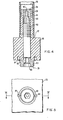
- Figure 2 is a view on elevation, partly in section, of the arrangement used for connecting the bottom nozzle to a control rod guide thimble;
- Figure 3 is a bottom view of the arrangement illustrated in Figure 2;
- Figure 4 is a view on elevation, partly in section, of a modified arrangement used for fastening a bottom nozzle to a control rod guide thimble; and
- Figure 5 is a bottom view of the arrangement illustrated in Figure 4.
- Figure 6 illustrates the design of a thimble screw tool used for effecting installation and removal of fasteners in the bottom nozzle.
- Referring now to the drawings, wherein like reference characteristics designate like or corresponding parts throughout the several views, there is shown in Figure 1 a portion of a nuclear
reactor fuel assembly 10 which includesmultiple fuel rods 12 held in radial spaced relationship with each other by a number ofgrids 14 spaced along the fuel rod length. In a conventional 17 X 17 fuel assembly design, the fuel rods range in length to about 14 feet and either eight or ninegrids 14 are spaced along the fuel assembly length. A number of control rod guide tubes orthimbles 16 are strategically interspersed among the fuel rods and are of a size sufficient to accept control rods which are used in helping control the fission process in the reactor. The guide thimbles are attached to atop nozzle 18 through asleeve 20 which,is secured to thetop nozzle 18 by welds 22. Outwardly projecting bulges 24 made in both the sleeve and guide thimble at 90° intervals secure the parts to each other. - The control
rod guide tubes 16 are similarly attached to the abottom nozzle 26 which is designed to absorb the weight of the components located thereabove in addition to directing the flow of coolant up through the fuel assembly. As shown in Figure 2, each controlrod guide tube 16 is attached to thebottom nozzle 26 through agrid insert sleeve 28 and afastener 30. Thesleeve 28 is of tubular configuration and is of a size to just contain the end of theguide thimble 16. Thelower end 32 is machined flat to sit firmly on theupper surface 34 of thebottom nozzle 26. Anend plug 36 welded into the end of each controlrod guide tube 16 has a central passage threaded at 38 along its length.Stainless steel fastener 30 used for joining the parts together, carriesexternal threads 40 which mate with thecomplementary threads 38 formed on the end plug inner surface and is of a length sufficient to extend substantially the full length ofend plug 36. - It will be-apparent that the design of the parts promotes great ease in assembling the bottom nozzle to the guide tube assembly during the course of manufacture. To accomplish this, during reconstitution of the fuel assemly, it is placed in an inverted position such that the bottom of the assembly will be uppermost but nevertheless still at a level approximately 12 feet below the surface of the water in the refueling chamber. Since the overall length of the
thimble screw fastener 30 is only about 4.8 cm. and a maximum diameter at the threads of 6.3 mm., and in view of the fact that none of the parts may be permitted to escape from the handling tools, it is evident that the parts must be designed to facilitate ease of replacement and must contain a high degree of simplicity and reliability if successful reconstitution is to take place in the approximately 20 foot distance. Theend 42 offastener 30 is of long narrow construction which serves as a lead-in guide for the fastener when it is inserted intonozzle 26 and the guidetube end plug 36. To preclude hang up of the fastener during the time of insertion, the fastener shank slopes outwardly at a 45° angle to provide aslanted surface 44 which helps the fastener slide into the end plug axial opening. The slanted surface merges into a relatively longcylindrical barrel 46 having a smooth outer surface and its diameter is only slightly less than the end plug annular opening. Since the barrel is relatively long compared to the fastener length, it acts to accurately orient and align the fastener shank in the end plug before engagement of thecomplementary threads portions sloped surface 48. Reference to Figure 2 will show that the threads actually start or are cut into thissloped surface 48. By designing the fastener in this manner, it will be evident that smooth transition will take place at the junction ofthreads - The
head end 50 of the fastener is in the nature of a locking cup which locks the fastener in position after the parts are joined together. It includes a wide flange 52 designed to engage a complementary machinedsurface 54 which serves a torquing base when the fastener draws thegrid insert sleeve 28 and guidetube end plug 36 into engagement with the bottomnozzle top surface 34. - The
head 50 further includes at its lower end, a relatively thincylindrical wall 56 of cup-like configuration which locks the fastener to the nozzle body. It projects outwardly from the fastener head and is sufficiently thin to be readily deformed by a tool which swages the wall material into cavities 58 (Figures 2 and 3) machined in the fastener body. Doing so positively locks the fastener to the nozzle and prevents its dislocation therefrom when acted on by vibratory and hydraulic forces acting within an operating reactor. Ahexagonal opening 60 in the center of the fastener head leads into apassage way 62 which extends to the complete length to the fastener, the purpose being to positively permit a metered amount of coolant to always flow through the guide thimble to which it is attached. - The fastener head is designed to accept a thimble screw installation and
removal tool 61, Figure 6, used to effect fastener engagement/disengagement with the nozzle and guide tube assembly. Anannular groove 63 on the fastener head outer surface facilitates locking engagement of the tool with the fastener prior to and during the time it is rotated into the guide tube end plug. As shown in Figure 6, thetool 61 which is about 14-18 feet long, includes a longcylindrical member 64 having ahandle 66 or other means on its upper end to facilitate rotating the tool in either direction. Theshaft 68 immovably fixed at one end 70 in the cylinder contains astop 72 pinned or otherwise attached to theshaft 68. Thelower end 74 of - the shaft is shaped to a hexagonal configuration and includes aflange 76 which limits downward movement ofhousing 78 carried by the shaft.Detent pins 80 having spring loaded ball ends are mounted through the wall of the tool housing and are biased bysprings 82 into engagement withgroove 63 in the fastener head outer surface when it is desired to insert or remove a fastener fromnozzle 26 and the guidetube end plug 36.Spring 84 acts betweenstop 72 andhousing 78 to always urgedhousing 78 downwardly to effect engagement of theballs 80 with the grooved formed in the fastener outer surface. - The modification illustrated in Figures 4 and 5 varies in design from the above-described locking cup arrangement in the structure of the fastener head. As shown, the fastener head 30 projects outwardly from the nozzle lower surface and is equipped with
locking groove 63 and hex opening 60 as shown in the Figure 2 embodiment. Anannular flange 82 extending radially outward from the fastener head body overlies a pair of opposite disposedslots 84, the arrangement being such that after the fastener is torqued into its final position, a tool is employed to deform portions of the flange into theslots 84 on the nozzle surface to thus lock the fastener to the nozzle body. - To remove defective fuel rods from an irradiated fuel assembly, after removal of the reactor head, the assembly is transferred to a spent fuel pool at the reactor site. It is inverted 180° and kept submerged beneath about 20 feet of water. Welds which secure fasteners of prior design to the nozzle body, are severed by means of open end mills mounted in a precision, aligned fixture or similar means. In the case of specially designed bottom nozzles of the kind disclosed in this application, the
removal tool 61 is placed in contact with the surface of the nozzle so that thehousing 78 overlies the fastener to be-removed. Since a portion of the fastener is swaged into the locking slots, after the tool is inserted into the fastener head and rotated, the material is sufficiently thin and flexible as to be dislodged from the slots. Continued rotation of thetool 61 will cause thefastener 30 to withdraw from the guide tube end plug to a point where thesprings 82urge ball 80 into contact with thegroove 63 on the fastener head. Further rotation of the tool thereby withdraws the fastener completely from the nozzle end guide tube end plug. This step is then repeated for each of the fastener attached to the nozzle and corresponding guide thimble end plugs in the fuel assembly. The nozzle is then removed from the fuel assembly and all fasteners and the bottom nozzle are placed in containers for eventual off-site shipment. After the defective fuel rods have been removed from the assembly, and the insertion of replacement rods into the assembly, either of the same or a replacement bottom nozzle is properly aligned against the lower ends of the fuel assembly guide thimbles using the necessary fixtures and long handled tooling. The fasteners are then inserted and torqued to a desired amount. After all thimble screws have been installed, a suitable long handled crimping tool is used to deform the integral locking device on each screw into the corresponding slots in the bottom nozzle.
Claims (6)
Applications Claiming Priority (2)
| Application Number | Priority Date | Filing Date | Title |
|---|---|---|---|
| US18693780A | 1980-09-12 | 1980-09-12 | |
| US186937 | 1980-09-12 |
Publications (2)
| Publication Number | Publication Date |
|---|---|
| EP0048343A1 true EP0048343A1 (en) | 1982-03-31 |
| EP0048343B1 EP0048343B1 (en) | 1985-04-10 |
Family
ID=22686908
Family Applications (1)
| Application Number | Title | Priority Date | Filing Date |
|---|---|---|---|
| EP81106498A Expired EP0048343B1 (en) | 1980-09-12 | 1981-08-21 | Reconstitutable fuel assembly for a nuclear reactor |
Country Status (11)
| Country | Link |
|---|---|
| EP (1) | EP0048343B1 (en) |
| JP (1) | JPS5779495A (en) |
| KR (1) | KR900000690B1 (en) |
| AU (1) | AU540259B2 (en) |
| DE (1) | DE3169835D1 (en) |
| ES (1) | ES505437A0 (en) |
| FR (1) | FR2490393B1 (en) |
| GR (1) | GR75025B (en) |
| IL (1) | IL63580A (en) |
| IT (1) | IT1138593B (en) |
| ZA (1) | ZA815600B (en) |
Cited By (12)
| Publication number | Priority date | Publication date | Assignee | Title |
|---|---|---|---|---|
| FR2539548A1 (en) * | 1983-01-17 | 1984-07-20 | Fragema Framatome & Cogema | Fuel assembly for nuclear reactor |
| FR2541809A1 (en) * | 1983-02-25 | 1984-08-31 | Framatome Sa | COMBUSTIBLE ASSEMBLY FOR A NUCLEAR REACTOR |
| EP0130840A2 (en) * | 1983-07-01 | 1985-01-09 | Quadrex Corporation | Alignment pin for guide tube assembly in nuclear power plant reactor vessel |
| EP0168670A1 (en) * | 1984-07-02 | 1986-01-22 | Westinghouse Electric Corporation | Fuel assembly |
| EP0186012A1 (en) * | 1984-12-20 | 1986-07-02 | Westinghouse Electric Corporation | A vented upper retainer for facilitating replacement of a top nozzle subassembly on a reconstituted nuclear fuel assembly |
| US4668469A (en) * | 1985-06-10 | 1987-05-26 | Westinghouse Electric Corp. | Fastener locking device for attaching guide thimble to fuel assembly bottom nozzle |
| US4687631A (en) * | 1985-09-12 | 1987-08-18 | Westinghouse Electric Corp. | Top nozzle mounted reusable fastener device in a reconstitutable nuclear fuel assembly |
| US4704246A (en) * | 1984-06-06 | 1987-11-03 | Westinghouse Electric Corp. | Crimping |
| EP0268807A2 (en) * | 1986-11-21 | 1988-06-01 | Westinghouse Electric Corporation | Nuclear fuel assembly bottom nozzle attachment system allowing reconstitution |
| EP0723271A1 (en) * | 1995-01-17 | 1996-07-24 | General Electric Company | Fuel rods and end plugs |
| CN103377718A (en) * | 2012-04-18 | 2013-10-30 | 巴布科克和威尔科克斯核作业集团股份有限公司 | Locking fastener for securing components in a nuclear reactor |
| CN109844870A (en) * | 2017-09-29 | 2019-06-04 | Tvel股份公司 | Reactor fuel assemblies |
Citations (10)
| Publication number | Priority date | Publication date | Assignee | Title |
|---|---|---|---|---|
| US1516957A (en) * | 1922-12-06 | 1924-11-25 | Matthew L Davis Sr | Locomotive driving gear |
| GB1045850A (en) * | 1964-10-08 | 1966-10-19 | Commissariat Energie Atomique | Closure device for nuclear fuel elements |
| GB1238143A (en) * | 1969-05-19 | 1971-07-07 | ||
| US3791466A (en) | 1969-05-19 | 1974-02-12 | Westinghouse Electric Corp | Low parasitic capture fuel assembly structure |
| US3864211A (en) * | 1972-10-02 | 1975-02-04 | Exxon Nuclear Co Inc | Removable upper tie plate |
| US3953287A (en) * | 1973-08-06 | 1976-04-27 | Exxon Nuclear Company, Inc. | Assembly mechanism for nuclear fuel bundles |
| GB1523770A (en) * | 1974-12-30 | 1978-09-06 | Asea Atom Ab | Fuel assemblies for nuclear reactors |
| US4119489A (en) * | 1975-01-08 | 1978-10-10 | Hitachi, Ltd. | Method of using nuclear reactor fuel assembly |
| GB1550541A (en) * | 1976-02-23 | 1979-08-15 | Exxon Nuclear Co Inc | Assembly mechanism for nuclear fuel bundles |
| GB2021303A (en) * | 1978-05-19 | 1979-11-28 | Framatome Sa | Nuclear reactor fuel assemblies |
Family Cites Families (11)
| Publication number | Priority date | Publication date | Assignee | Title |
|---|---|---|---|---|
| GB107352A (en) * | 1916-11-14 | 1917-06-28 | Laurent Gustave Gerard Dibbets | Improvements in Nut Locks. |
| DE922871C (en) * | 1953-01-13 | 1955-01-27 | Johann Stiel | Knurled screw |
| FR83706E (en) * | 1961-07-29 | 1964-10-02 | Perforated rim bolt | |
| GB1105275A (en) * | 1965-11-23 | 1968-03-06 | Normalized Bolts Ltd | Screws |
| DE2151932A1 (en) * | 1971-10-19 | 1973-04-26 | Zahnradfabrik Friedrichshafen | SCREW LOCKING |
| US3992259A (en) * | 1973-06-25 | 1976-11-16 | Combustion Engineering, Inc. | Fuel assembly for a nuclear reactor |
| US4036692A (en) * | 1975-08-01 | 1977-07-19 | The Babcock & Wilcox Company | Nuclear fuel element nut retainer cup |
| AT345621B (en) * | 1976-09-21 | 1978-09-25 | Andritz Ag Maschf | SCREW LOCKING |
| FR2368785A1 (en) * | 1976-10-20 | 1978-05-19 | Framatome Sa | EASY DISASSEMBLY FUEL ASSEMBLY FOR NUCLEAR REACTOR |
| US4105058A (en) * | 1977-03-31 | 1978-08-08 | Ball Valve Company, Inc. | Screw locking arrangement |
| JPS5499953U (en) * | 1977-12-26 | 1979-07-14 |
-
1981
- 1981-08-13 ZA ZA815600A patent/ZA815600B/en unknown
- 1981-08-13 AU AU74053/81A patent/AU540259B2/en not_active Ceased
- 1981-08-14 IL IL63580A patent/IL63580A/en unknown
- 1981-08-21 DE DE8181106498T patent/DE3169835D1/en not_active Expired
- 1981-08-21 EP EP81106498A patent/EP0048343B1/en not_active Expired
- 1981-09-08 GR GR65981A patent/GR75025B/el unknown
- 1981-09-10 IT IT23874/81A patent/IT1138593B/en active
- 1981-09-11 ES ES505437A patent/ES505437A0/en active Granted
- 1981-09-11 FR FR8117241A patent/FR2490393B1/en not_active Expired
- 1981-09-11 KR KR1019810003390A patent/KR900000690B1/en active
- 1981-09-11 JP JP56142541A patent/JPS5779495A/en active Granted
Patent Citations (10)
| Publication number | Priority date | Publication date | Assignee | Title |
|---|---|---|---|---|
| US1516957A (en) * | 1922-12-06 | 1924-11-25 | Matthew L Davis Sr | Locomotive driving gear |
| GB1045850A (en) * | 1964-10-08 | 1966-10-19 | Commissariat Energie Atomique | Closure device for nuclear fuel elements |
| GB1238143A (en) * | 1969-05-19 | 1971-07-07 | ||
| US3791466A (en) | 1969-05-19 | 1974-02-12 | Westinghouse Electric Corp | Low parasitic capture fuel assembly structure |
| US3864211A (en) * | 1972-10-02 | 1975-02-04 | Exxon Nuclear Co Inc | Removable upper tie plate |
| US3953287A (en) * | 1973-08-06 | 1976-04-27 | Exxon Nuclear Company, Inc. | Assembly mechanism for nuclear fuel bundles |
| GB1523770A (en) * | 1974-12-30 | 1978-09-06 | Asea Atom Ab | Fuel assemblies for nuclear reactors |
| US4119489A (en) * | 1975-01-08 | 1978-10-10 | Hitachi, Ltd. | Method of using nuclear reactor fuel assembly |
| GB1550541A (en) * | 1976-02-23 | 1979-08-15 | Exxon Nuclear Co Inc | Assembly mechanism for nuclear fuel bundles |
| GB2021303A (en) * | 1978-05-19 | 1979-11-28 | Framatome Sa | Nuclear reactor fuel assemblies |
Cited By (20)
| Publication number | Priority date | Publication date | Assignee | Title |
|---|---|---|---|---|
| FR2539548A1 (en) * | 1983-01-17 | 1984-07-20 | Fragema Framatome & Cogema | Fuel assembly for nuclear reactor |
| FR2541809A1 (en) * | 1983-02-25 | 1984-08-31 | Framatome Sa | COMBUSTIBLE ASSEMBLY FOR A NUCLEAR REACTOR |
| EP0118355A1 (en) * | 1983-02-25 | 1984-09-12 | Framatome | Nuclear reactor fuel assembly |
| EP0130840A2 (en) * | 1983-07-01 | 1985-01-09 | Quadrex Corporation | Alignment pin for guide tube assembly in nuclear power plant reactor vessel |
| EP0130840A3 (en) * | 1983-07-01 | 1985-05-29 | Quadrex Corporation | Alignment pin for guide tube assembly in nuclear power plant reactor vessel |
| US4704246A (en) * | 1984-06-06 | 1987-11-03 | Westinghouse Electric Corp. | Crimping |
| EP0168670A1 (en) * | 1984-07-02 | 1986-01-22 | Westinghouse Electric Corporation | Fuel assembly |
| EP0186012A1 (en) * | 1984-12-20 | 1986-07-02 | Westinghouse Electric Corporation | A vented upper retainer for facilitating replacement of a top nozzle subassembly on a reconstituted nuclear fuel assembly |
| US4668469A (en) * | 1985-06-10 | 1987-05-26 | Westinghouse Electric Corp. | Fastener locking device for attaching guide thimble to fuel assembly bottom nozzle |
| US4687631A (en) * | 1985-09-12 | 1987-08-18 | Westinghouse Electric Corp. | Top nozzle mounted reusable fastener device in a reconstitutable nuclear fuel assembly |
| EP0268807A2 (en) * | 1986-11-21 | 1988-06-01 | Westinghouse Electric Corporation | Nuclear fuel assembly bottom nozzle attachment system allowing reconstitution |
| EP0268807A3 (en) * | 1986-11-21 | 1989-02-22 | Westinghouse Electric Corporation | Nuclear fuel assembly bottom nozzle attachment system allowing reconstitution |
| EP0723271A1 (en) * | 1995-01-17 | 1996-07-24 | General Electric Company | Fuel rods and end plugs |
| US5608768A (en) * | 1995-01-17 | 1997-03-04 | General Electric Company | Threaded fuel rod end plugs and related method |
| CN103377718A (en) * | 2012-04-18 | 2013-10-30 | 巴布科克和威尔科克斯核作业集团股份有限公司 | Locking fastener for securing components in a nuclear reactor |
| WO2013165526A2 (en) * | 2012-04-18 | 2013-11-07 | Babcock & Wilcox Nuclear Operations Group, Inc. | Locking fastener for securing components in a nuclear reactor |
| WO2013165526A3 (en) * | 2012-04-18 | 2014-01-23 | Babcock & Wilcox Nuclear Operations Group, Inc. | Locking fastener for securing components in a nuclear reactor |
| US9530525B2 (en) | 2012-04-18 | 2016-12-27 | Bwxt Nuclear Operations Group, Inc. | Locking fastener for securing components in a nuclear reactor |
| CN109844870A (en) * | 2017-09-29 | 2019-06-04 | Tvel股份公司 | Reactor fuel assemblies |
| CN109844870B (en) * | 2017-09-29 | 2023-11-17 | Tvel股份公司 | reactor fuel assembly |
Also Published As
| Publication number | Publication date |
|---|---|
| AU540259B2 (en) | 1984-11-08 |
| DE3169835D1 (en) | 1985-05-15 |
| AU7405381A (en) | 1982-03-18 |
| KR900000690B1 (en) | 1990-02-03 |
| JPS5779495A (en) | 1982-05-18 |
| FR2490393A1 (en) | 1982-03-19 |
| ES8404087A1 (en) | 1984-04-01 |
| JPS6331065B2 (en) | 1988-06-22 |
| ZA815600B (en) | 1982-08-25 |
| FR2490393B1 (en) | 1985-06-28 |
| ES505437A0 (en) | 1984-04-01 |
| EP0048343B1 (en) | 1985-04-10 |
| KR830008327A (en) | 1983-11-18 |
| IT8123874A0 (en) | 1981-09-10 |
| GR75025B (en) | 1984-07-12 |
| IT1138593B (en) | 1986-09-17 |
| IL63580A (en) | 1984-12-31 |
Similar Documents
| Publication | Publication Date | Title |
|---|---|---|
| US8483346B2 (en) | Nuclear reactor control rod spider assembly | |
| US4323428A (en) | Reconstitutable fuel assembly for a nuclear reactor | |
| EP0048343B1 (en) | Reconstitutable fuel assembly for a nuclear reactor | |
| US7668284B2 (en) | Tube-in-tube threaded dashpot end plug | |
| US7453972B2 (en) | Nuclear fuel assembly control rod drive thimble to bottom nozzle connector | |
| JP5330634B2 (en) | Reactor fuel bundle and manufacturing method thereof | |
| US5207980A (en) | Top nozzle-mounted replacement guide pin assemblies | |
| US5141711A (en) | Reconstitutable control assembly having removable control rods with detachable split upper end plugs | |
| US4888151A (en) | Reconstitutable control assembly having removable control rods with detachable split upper end plugs | |
| US4993864A (en) | Reconstitutable control assembly having removable control rods with detachable split upper end plugs | |
| US4820479A (en) | Guide pin assembly for a nuclear reactor | |
| US5297176A (en) | Remotely replaceable fuel assembly alignment pin | |
| US4664874A (en) | Reusable locking tube insertion and removal fixture and method in a reconstitutable fuel assembly | |
| US4738820A (en) | Nuclear fuel assembly bottom nozzle attachment system allowing reconstitution | |
| US4855100A (en) | Reconstitutable control rod spider assembly | |
| US4716018A (en) | End plug with truncated tapered leading end configuration | |
| EP0206586A2 (en) | Double lock joint for attaching top nozzle to guide thimbles of nuclear fuel assembly | |
| JPS6266193A (en) | Reusable clamping device in fuel aggregate | |
| EP0593295B1 (en) | Control rod spacer pad | |
| US4738821A (en) | Reconstitutable nuclear fuel assembly having locking tubes with dimples | |
| JPS60136609A (en) | Connecting structure of detachable socket and pipe | |
| KR100844474B1 (en) | Easy release and coupling joint between upper-end-fitting and guide tube | |
| EP0212902A2 (en) | Method of removing and replacing locking screws in a nuclear fuel assembly | |
| US10510451B2 (en) | Base plate mounted core components for reliable rod assembly and rapid field disassembly | |
| US4799312A (en) | Tool for replacing locking screws in a nuclear fuel assembly |
Legal Events
| Date | Code | Title | Description |
|---|---|---|---|
| PUAI | Public reference made under article 153(3) epc to a published international application that has entered the european phase |
Free format text: ORIGINAL CODE: 0009012 |
|
| AK | Designated contracting states |
Designated state(s): BE CH DE GB SE |
|
| 17P | Request for examination filed |
Effective date: 19820825 |
|
| GRAA | (expected) grant |
Free format text: ORIGINAL CODE: 0009210 |
|
| AK | Designated contracting states |
Designated state(s): BE CH DE GB LI SE |
|
| REF | Corresponds to: |
Ref document number: 3169835 Country of ref document: DE Date of ref document: 19850515 |
|
| PLBI | Opposition filed |
Free format text: ORIGINAL CODE: 0009260 |
|
| 26 | Opposition filed |
Opponent name: FRAMATOME, S.A. Effective date: 19851118 |
|
| PGFP | Annual fee paid to national office [announced via postgrant information from national office to epo] |
Ref country code: GB Payment date: 19890630 Year of fee payment: 9 |
|
| PGFP | Annual fee paid to national office [announced via postgrant information from national office to epo] |
Ref country code: CH Payment date: 19890831 Year of fee payment: 9 |
|
| RDAG | Patent revoked |
Free format text: ORIGINAL CODE: 0009271 |
|
| STAA | Information on the status of an ep patent application or granted ep patent |
Free format text: STATUS: PATENT REVOKED |
|
| GBPR | Gb: patent revoked under art. 102 of the ep convention designating the uk as contracting state | ||
| 27W | Patent revoked |
Effective date: 19890824 |
|
| REG | Reference to a national code |
Ref country code: CH Ref legal event code: PL |
|
| PGFP | Annual fee paid to national office [announced via postgrant information from national office to epo] |
Ref country code: SE Payment date: 19900625 Year of fee payment: 10 |
|
| PGFP | Annual fee paid to national office [announced via postgrant information from national office to epo] |
Ref country code: BE Payment date: 19900712 Year of fee payment: 10 |
|
| BERE | Be: lapsed |
Owner name: WESTINGHOUSE ELECTRIC CORP. Effective date: 19910831 |
|
| EUG | Se: european patent has lapsed |
Ref document number: 81106498.9 |
|
| APAH | Appeal reference modified |
Free format text: ORIGINAL CODE: EPIDOSCREFNO |