EP0048310A1 - Liquid-gas separator - Google Patents
Liquid-gas separator Download PDFInfo
- Publication number
- EP0048310A1 EP0048310A1 EP80303313A EP80303313A EP0048310A1 EP 0048310 A1 EP0048310 A1 EP 0048310A1 EP 80303313 A EP80303313 A EP 80303313A EP 80303313 A EP80303313 A EP 80303313A EP 0048310 A1 EP0048310 A1 EP 0048310A1
- Authority
- EP
- European Patent Office
- Prior art keywords
- filter
- agglomerator
- air
- layers
- separator
- Prior art date
- Legal status (The legal status is an assumption and is not a legal conclusion. Google has not performed a legal analysis and makes no representation as to the accuracy of the status listed.)
- Granted
Links
Images


Classifications
-
- B—PERFORMING OPERATIONS; TRANSPORTING
- B01—PHYSICAL OR CHEMICAL PROCESSES OR APPARATUS IN GENERAL
- B01D—SEPARATION
- B01D46/00—Filters or filtering processes specially modified for separating dispersed particles from gases or vapours
- B01D46/0027—Filters or filtering processes specially modified for separating dispersed particles from gases or vapours with additional separating or treating functions
- B01D46/003—Filters or filtering processes specially modified for separating dispersed particles from gases or vapours with additional separating or treating functions including coalescing means for the separation of liquid
- B01D46/0031—Filters or filtering processes specially modified for separating dispersed particles from gases or vapours with additional separating or treating functions including coalescing means for the separation of liquid with collecting, draining means
-
- B—PERFORMING OPERATIONS; TRANSPORTING
- B01—PHYSICAL OR CHEMICAL PROCESSES OR APPARATUS IN GENERAL
- B01D—SEPARATION
- B01D46/00—Filters or filtering processes specially modified for separating dispersed particles from gases or vapours
- B01D46/24—Particle separators, e.g. dust precipitators, using rigid hollow filter bodies
- B01D46/2403—Particle separators, e.g. dust precipitators, using rigid hollow filter bodies characterised by the physical shape or structure of the filtering element
- B01D46/2411—Filter cartridges
-
- B—PERFORMING OPERATIONS; TRANSPORTING
- B01—PHYSICAL OR CHEMICAL PROCESSES OR APPARATUS IN GENERAL
- B01D—SEPARATION
- B01D46/00—Filters or filtering processes specially modified for separating dispersed particles from gases or vapours
- B01D46/52—Particle separators, e.g. dust precipitators, using filters embodying folded corrugated or wound sheet material
- B01D46/521—Particle separators, e.g. dust precipitators, using filters embodying folded corrugated or wound sheet material using folded, pleated material
-
- B—PERFORMING OPERATIONS; TRANSPORTING
- B01—PHYSICAL OR CHEMICAL PROCESSES OR APPARATUS IN GENERAL
- B01D—SEPARATION
- B01D2275/00—Filter media structures for filters specially adapted for separating dispersed particles from gases or vapours
- B01D2275/10—Multiple layers
Definitions
- This invention relates generally to liquid separators having plural distinct elements mounted concentrically. More particularly, this invention has reference to an air-oil separator having pleated agglomerator media.
- the present invention overcomes many of,the problems which exist in the prior art devices.
- the present invention provides a two-stage air-oil separator connected to the exhaust system of an air compressor.
- the first stage has a pleated extended area agglomerator formed of layered material.
- the pleated filter permits significant reduction in the size of the overall separator for a given air flow capacity.
- the pleated agglomerator medium used in the first stage has layers of fiberglass positioned between screens. This agglomerator medium, when pleated, causes little pressure drop in the air passing through the separator.
- this particular first stage avoids the problem of excessive compressing of agglomerator media common in prior art devices.
- the second stage has radially spaced filter elements with high loft filter material layers held between vinyl coated glass scrims. Such a double second stage filter element permits further reduction in size. By wrapping the layers in the various filter elements with different degrees of tightness, improved filtration efficiency and effectiveness occur with a minimum pressure drop.
- the separator of the present invention is shown generally by the numeral 1.
- the general purpose of the separator 1 is to remove oil mist from the pressurized air exhausted from a compressor outlet.
- the separator 1 has two stages.
- the agglomerator stage 4 is positioned adjacent the outer wall 2 of the separator 1.
- the second stage is a double filtering stage having two filter elements 6 and 10 positioned adjacent inner walls 8 and 12 of the separator 1.
- the separator walls 2, 8 and 12 are perforated steel cylinders.
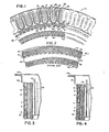
- the agglomerator 4 has a pleated multilayer agglomerator media.
- the outer layer 20 of the agglomerator media is a single layer of mesh metal screen.
- the inner layer 30 is a single layer of mesh metal screen.
- the central layer 24 of the agglomerator media is a single layer of fiber glass sheet.
- Positioned between the fiber glass sheet 24 and the adjacent mesh metal screens 20 and 30 are intermediate layers 22, 26 and 28 formed of a fiber glass media.
- a single layer of fiber glass media 22 is positioned between the fiber glass sheet 24 and the outer screen 20.
- Two layers of fiber glass media 26 and 28 are positioned between the fiber glass sheet 24 and the inner screen 30.
- the fiber glass sheet 24 has a low loft and the fiber glass media 22, 26 and 28 has a substantially higher loft. The latter may be used without the low loft sheet..
- agglomerator materials may be substituted without departing from the scope of the present invention.
- various other layering arrangements which will be obvious to persons skilled in the art do not depart from the scope of the present invention.
- the specific agglomerator materials and layering arrangement described is preferred.
- This agglomerator structure proved high resistant to compressive forces exerted by the pressurized air passing through the filter.
- the preferred agglomerator 4 caused little pressure drop in the air passing through the filter and performed the agglomerating function, later described in greater detail, effectively.
- the filter elements 6 and 10 in the second stage have two layers of filter media 31 and 33 positioned between vinyl coated glass scrims 32, 34, 36 and 38.
- the outer filter element 6 is held against the inner circumference of the agglomerator 4 by a perforated steel cylinder 8 concentrically spaced within the outer wall 2 of the separator 1.
- the inner filter element -10 is secured adjacent the inner wall 12 of the separator l..
- a cylindrical space 35 is provided between the inner and outer. filter elements 6 and 10.
- the filter elements 6 and 10 separate oil from-air in a manner more fully described later.
- the second stage facilitates. the draining of the oil.
- the dual element filtering configuration used in the present invention further permits a reduction in the overall size of the separator 1 for a given air flow capacity.
- the separator 40 show: in Figure 2 is similar to those generally used in the prior art to separate oil mist from compressor exhaust air.
- the prior art separator has three radially spaced concentric perforated steel cylinders 42, 46 and 50.
- the outer filtering stage has a plurality of layers of fiber glass media 44 positioned between concentrically spaced glass scrims 41 and 43.
- the outer filter element is held between the outer and central steel cylinders 42 and 46.
- the inner filter element has a plurality of layers of fiber glass media 48 held between a vinyl coated glass scrim 45 and the inner perforated steel cylinder 50.
- the prior art separator 40 has less oil loading surface area than the pleated separator 1 of the present invention.
- the present separator 1 can be made much smaller than the prior art separator 40 and still handle the same air flow capacity.
- the plurality of fiber glass media wrappings 44 and 48 in the prior art separator 40 tend to compress and compact more easily than the agglomerating and filter media in the present separator 1 when subjected to high pressure air streams.
- the fiber glass media layers 44 and 48 in the prior art separator 40 are compressed, a significant pressure drop occurs.
- the present I separator 1 avoids this problem.
- FIGS 3-10 show various embodiments of the present invention and various mounting supports used with the present invention.
- Figure 3 has a single second stage 10 supported between a perforated inner wall 12 and scrim 32.
- Figure 4 employs a dual second stage, Filter 6 is added between pleated accumulation 4 and perforated cylinder 8. Mounting end 64 is supplied with gaskets 8 4 . Tube 90 withdraws oil from within the filter. Straps 93 hold the casings assembled.
- Figure 5 shows a vertically mounted separator.
- An inlet port 94 formed in the side wall of a compressor oil sump 86 is connected to the pressurized air outlet (now shown) of an air compressor. Pressurized air enters the port 94 and impinges upon the separator.
- Oil 97 within the tank is returned to the compressor through pipe 96 which extends to a point near the bottom of the tank.
- Heavy screen 8 supports the pleated element 4 against the pressure differential, while the oil is being agglomerated into large drops by the separator element 4.
- the air continues through second stage element 6 which is supported by a perforated cylinder 7, and oil free dry air goes out of the large pipe at the top of the separator.
- Some oil collects on the outer screen 2 and flows downward, collecting at the bottom of the main tank.
- Other oil flows through the stages of the separator and is collected at the base 56 of the separator.
- Oil tube 90 leads the oil from the relatively high pressure interior of the separator to the atmospheric pressure intake of the compressor.
- the separator shown in Figure 6 and its detail shown in Figure 7 flow oil mist laden air from the inside of separator 100 through the outside.
- the oil laden air flows in through an opening in one of the ends 110 or 112, and the air flows radially outward through the filter elements.
- Oil free dry air is collected in a circumferential shroud and is piped to a cooler or to another device or use.
- the oil mist laden air infringes upon screen 2 and flows through pleated layered agglomerator 4. Some of the oil drips from the screen 2 and the inside of element 4 downward through the open lower end 112 into the oil sump tank. The air continues outward through the heavy perforated radial thrust cylinder 8 and through the grid 9 around which filter element 6 is wrapped.
- the air continues outward through the second stage filter element 6 and through the relatively light perforated metal cylinder, grid or screen 7, where the oil free air is collected and used.
- a tube in the outer shroud similar to tube 90 collects oil which has flowed through the separator elements and returns oil to the compressor.
- a horizontal mounting of the separator unit is shown in Figure 8.
- a tank 140 has a heavy cylinder 142 with a welded end plate 144.
- a separator unit is inserted through a large upper opening in end plate 144 and a cover plate 146 is bolted to the end plate with the gasketed filter flanges in between.
- a central opening 148 in cover plate 146 flows oil free dry compressed air outward through connected piping, which is not shown.
- An oil opening 150 near the bottom of the plate is connected to piping which flows oil to the intake of a compressor. Oil is collected in a low spot near the cover plate and near opening 150 as it drops from short tube 152 which is inserted through end cap 158 between the first and second-stages 4 and 6.
- a double second stage element is mounted horizontally within the tank similar to the tank i. shown in Figure 8. Oil which collects between first and second stages flows outward through a short pipe 152 and through oil opening 150 in cover plate 146.
- the double second stage separator shown in Figure 9 is similar to the separator shown in Figure 8 with the addition of second stage filter material 6 which is wrapped around an inner perforated cylinder 8. Oil migrates to the area where it is removed by short tube 152.
- FIG 10 shows a horizontal embodiment of the invention.
- Pleated agglomerator 4 is mounted on a horizontal axis.
- Dual secondary elements are in the form of discs 74 and 78, having compositions similar to filter elements 6 and 10 as shown in Figure 1.
- a cup-shaped mount 64 has welded straps 78 and 82 secured thereto to support a secondary filter disc assembly composed of inner and outer screens 72 and 80 and filter discs 74 and 78, which are separated by a foraminous metal disc 75. Flanges of the filter assembly are covered by gaskets 84 for mounting between a tank and cover. Primary filter 4 is supported between perforated plates 2 and 8 and straps 71 connect the inward base plate 56 to the remainder of the filter assembly.
- the horizontal version as shown in Figure 10 uses secondary stage filter discs 74 and 78 instead of the second stage cylinder.
Abstract
Description
- This invention relates generally to liquid separators having plural distinct elements mounted concentrically. More particularly, this invention has reference to an air-oil separator having pleated agglomerator media.
- Many problems remain in the prior art devices. One problem lies in the excessive pressure drop that occurs as the fluid passes through the filtering media. Another problem lies in the excessively large size required for prior art filters having an air flow capacity sufficient for use with compressors. Another problem lies in the tendence of prior art filtering media to compress under the air pressures encountered in a compressor exhaust system and thereby decrease the operating efficiency of the compressor system.
- The present invention overcomes many of,the problems which exist in the prior art devices. The present invention provides a two-stage air-oil separator connected to the exhaust system of an air compressor.
- The first stage has a pleated extended area agglomerator formed of layered material. The pleated filter permits significant reduction in the size of the overall separator for a given air flow capacity. The pleated agglomerator medium used in the first stage has layers of fiberglass positioned between screens. This agglomerator medium, when pleated, causes little pressure drop in the air passing through the separator. In addition, this particular first stage avoids the problem of excessive compressing of agglomerator media common in prior art devices.
- The second stage has radially spaced filter elements with high loft filter material layers held between vinyl coated glass scrims. Such a double second stage filter element permits further reduction in size. By wrapping the layers in the various filter elements with different degrees of tightness, improved filtration efficiency and effectiveness occur with a minimum pressure drop.
- Figure 1 is a fragmentary cross sectional view of the separator of the present invention.
- Figure 2 is a fragmentary cross sectional view of a typical prior art separator.
- Figure 3 is an elevational view, in section, of a portion of one embodiment of the separator of the present invention.
- Figure 4 is an elevational view, in section, of a portion of another embodiment of the separator of the present invention.
- Figure 5 is a perspective view, partly in section, of a separator installed vertically in an oil tank.
- Figure 6 is an elevational view, partially in section, showing a separator embodiment in which oil mist laden air flows from within the separator and clean air flows radially outward from the separator.
- Figure 7 is a detail of the separator embodiment shown in Figure 6.
- Figure 8 shows, horizontal installation of a separator with a single second stage.
- Figure 9 shows a detail of a similarly installed separator with a double second stage.
- Figure 10 shows a horizontal embodiment of a separator with second stage filter discs.
- Referring now to FIGURE 1, the separator of the present invention is shown generally by the numeral 1. As will become apparent, the general purpose of the separator 1 is to remove oil mist from the pressurized air exhausted from a compressor outlet.
- The separator 1 has two stages. The
agglomerator stage 4 is positioned adjacent theouter wall 2 of the separator 1. The second stage is a double filtering stage having twofilter elements inner walls separator walls - The
agglomerator 4 has a pleated multilayer agglomerator media. Theouter layer 20 of the agglomerator media is a single layer of mesh metal screen. Similarly, the inner layer 30 is a single layer of mesh metal screen. Thecentral layer 24 of the agglomerator media is a single layer of fiber glass sheet. Positioned between thefiber glass sheet 24 and the adjacentmesh metal screens 20 and 30 areintermediate layers fiber glass media 22 is positioned between thefiber glass sheet 24 and theouter screen 20. Two layers offiber glass media fiber glass sheet 24 and the inner screen 30. Preferably, thefiber glass sheet 24 has a low loft and thefiber glass media - Various other agglomerator materials may be substituted without departing from the scope of the present invention. Similarly, various other layering arrangements which will be obvious to persons skilled in the art do not depart from the scope of the present invention. However, the specific agglomerator materials and layering arrangement described is preferred. This agglomerator structure proved high resistant to compressive forces exerted by the pressurized air passing through the filter. In addition, the
preferred agglomerator 4 caused little pressure drop in the air passing through the filter and performed the agglomerating function, later described in greater detail, effectively. - The
filter elements filter media glass scrims outer filter element 6 is held against the inner circumference of theagglomerator 4 by a perforatedsteel cylinder 8 concentrically spaced within theouter wall 2 of the separator 1. The inner filter element -10 is secured adjacent theinner wall 12 of the separator l.. Acylindrical space 35 is provided between the inner and outer.filter elements - The
filter elements - Large radial forces are supported by
heavy cylinder 8.Layers 31 in theouter filter element 6 are wrapped tightly around the perforatedsteel cylinder 8 and thelayers 33 in theinner filtering element 10 are wrapped around theinner steel cylinder 12. This construction provides effective filtering capability with a minimum pressure drop in the air passing through the separator 1. - The
separator 40 show: in Figure 2 is similar to those generally used in the prior art to separate oil mist from compressor exhaust air. Generally, the prior art separator has three radially spaced concentric perforatedsteel cylinders glass scrims central steel cylinders fiber glass media 48 held between a vinyl coatedglass scrim 45 and the inner perforatedsteel cylinder 50. Theprior art separator 40 has less oil loading surface area than the pleated separator 1 of the present invention. Consequently, the present separator 1 can be made much smaller than theprior art separator 40 and still handle the same air flow capacity. In addition, the plurality of fiber glass media wrappings 44 and 48 in theprior art separator 40 tend to compress and compact more easily than the agglomerating and filter media in the present separator 1 when subjected to high pressure air streams. When the fiber glass media layers 44 and 48 in theprior art separator 40 are compressed, a significant pressure drop occurs. The present I separator 1 avoids this problem. - Figures 3-10 show various embodiments of the present invention and various mounting supports used with the present invention.
- Figure 3 has a single
second stage 10 supported between a perforatedinner wall 12 andscrim 32. Figure 4 employs a dual second stage,Filter 6 is added betweenpleated accumulation 4 andperforated cylinder 8. Mountingend 64 is supplied withgaskets 84.Tube 90 withdraws oil from within the filter.Straps 93 hold the casings assembled. - Figure 5 shows a vertically mounted separator. An
inlet port 94 formed in the side wall of acompressor oil sump 86 is connected to the pressurized air outlet (now shown) of an air compressor. Pressurized air enters theport 94 and impinges upon the separator. -
Oil 97 within the tank is returned to the compressor throughpipe 96 which extends to a point near the bottom of the tank. - Oil mist laden air enters the separator through
pleasted element 4 of the first stage.Heavy screen 8 supports thepleated element 4 against the pressure differential, while the oil is being agglomerated into large drops by theseparator element 4. The air continues throughsecond stage element 6 which is supported by aperforated cylinder 7, and oil free dry air goes out of the large pipe at the top of the separator. Some oil collects on theouter screen 2 and flows downward, collecting at the bottom of the main tank. Other oil flows through the stages of the separator and is collected at thebase 56 of the separator.Oil tube 90 leads the oil from the relatively high pressure interior of the separator to the atmospheric pressure intake of the compressor. - The separator shown in Figure 6 and its detail shown in Figure 7 flow oil mist laden air from the inside of separator 100 through the outside. The oil laden air flows in through an opening in one of the
ends - The oil mist laden air infringes upon
screen 2 and flows through pleatedlayered agglomerator 4. Some of the oil drips from thescreen 2 and the inside ofelement 4 downward through the openlower end 112 into the oil sump tank. The air continues outward through the heavy perforatedradial thrust cylinder 8 and through the grid 9 around whichfilter element 6 is wrapped. - The air continues outward through the second
stage filter element 6 and through the relatively light perforated metal cylinder, grid orscreen 7, where the oil free air is collected and used. A tube in the outer shroud similar totube 90 collects oil which has flowed through the separator elements and returns oil to the compressor. - A horizontal mounting of the separator unit is shown in Figure 8. A
tank 140 has aheavy cylinder 142 with a weldedend plate 144. A separator unit is inserted through a large upper opening inend plate 144 and acover plate 146 is bolted to the end plate with the gasketed filter flanges in between. - A
central opening 148 incover plate 146 flows oil free dry compressed air outward through connected piping, which is not shown. Anoil opening 150 near the bottom of the plate is connected to piping which flows oil to the intake of a compressor. Oil is collected in a low spot near the cover plate and near opening 150 as it drops fromshort tube 152 which is inserted throughend cap 158 between the first and second-stages - The filter elements and perforated plates andare held between

end caps Flanged cup 160 is welded to endcap 158 and extends outward between gaskets which separate the cup flange from thetank end plate 144 and thecover plate 146.Bolts 162 inserted through thecover plate 146 and the flange secure the cover plate and separator to theend plate 144 of the tank. Oil laden air flows through the outerperforated cylinder 2 and pleatedmultilayer agglomerator element 4. Some oil flows fromperforated plate 2 andelement 4 in the forms of large drops which drip intotank 140. Air and large drops of oil flow inward through heavy inward thrust sustainingperforated cylinder 8 and the air continues to flow through perforated cylinder 9,second stage element 6, andinner support plate 7. Oil is removed from between the first and second stages byshort tube 152 and flows into a lower area nearoil opening 150. - As shown in Figure 9, a double second stage element is mounted horizontally within the tank similar to the tank i. shown in Figure 8. Oil which collects between first and second stages flows outward through a
short pipe 152 and throughoil opening 150 incover plate 146. The double second stage separator shown in Figure 9 is similar to the separator shown in Figure 8 with the addition of secondstage filter material 6 which is wrapped around an innerperforated cylinder 8. Oil migrates to the area where it is removed byshort tube 152. - Figure 10 shows a horizontal embodiment of the invention.
Pleated agglomerator 4 is mounted on a horizontal axis. Dual secondary elements are in the form ofdiscs 74 and 78, having compositions similar to filterelements - A cup-shaped
mount 64 has weldedstraps outer screens filter discs 74 and 78, which are separated by aforaminous metal disc 75. Flanges of the filter assembly are covered bygaskets 84 for mounting between a tank and cover.Primary filter 4 is supported betweenperforated plates inward base plate 56 to the remainder of the filter assembly. - The horizontal version as shown in Figure 10 uses secondary
stage filter discs 74 and 78 instead of the second stage cylinder. - While the invention has been described with reference to specific embodiments, modifications and variations of the invention may be made without departing from the scope of the invention. The scope of the invention is described in the following claims.
Claims (12)
said sheet agglomerator material and said high loft agglomerator material comprise material fromed of glass fibers.
the annular pleated agglomerator media further comprises mesh screens received on the outer surfaces of the layers of high loft agglomerator material to maintain the outer peripheries of the agglomerator media in fixed relationship.
the mesh screens comprise mesh aluminum screens.
the flat sheet agglomerator material is interposed between a single layer of high loft agglomerator material and two superposed layers of high loft agglomerator material, said single layer received on the radially outward surface of the flat sheet agglomerator material.
the high loft filter material comprises material formed of synthetic material.
the sheets of permeable casing comprise vinyl coated glass scrims.
the filter means comprises radially spaced annular filter elements concentrically disposed about the core.
Priority Applications (2)
| Application Number | Priority Date | Filing Date | Title |
|---|---|---|---|
| DE8080303313T DE3071847D1 (en) | 1980-09-22 | 1980-09-22 | Liquid-gas separator |
| EP80303313A EP0048310B1 (en) | 1980-09-22 | 1980-09-22 | Liquid-gas separator |
Applications Claiming Priority (1)
| Application Number | Priority Date | Filing Date | Title |
|---|---|---|---|
| EP80303313A EP0048310B1 (en) | 1980-09-22 | 1980-09-22 | Liquid-gas separator |
Publications (2)
| Publication Number | Publication Date |
|---|---|
| EP0048310A1 true EP0048310A1 (en) | 1982-03-31 |
| EP0048310B1 EP0048310B1 (en) | 1986-12-03 |
Family
ID=8187263
Family Applications (1)
| Application Number | Title | Priority Date | Filing Date |
|---|---|---|---|
| EP80303313A Expired EP0048310B1 (en) | 1980-09-22 | 1980-09-22 | Liquid-gas separator |
Country Status (2)
| Country | Link |
|---|---|
| EP (1) | EP0048310B1 (en) |
| DE (1) | DE3071847D1 (en) |
Cited By (9)
| Publication number | Priority date | Publication date | Assignee | Title |
|---|---|---|---|---|
| US4693997A (en) * | 1982-03-12 | 1987-09-15 | Kabivitrum Ab | Novel pharmaceutical composition |
| US4723557A (en) * | 1983-10-03 | 1988-02-09 | Hospital For Joint Diseases Orthopedic Institute | Lordosimeter |
| US5768809A (en) * | 1996-12-23 | 1998-06-23 | Macneill Engineering Company, Inc. | Quick-release spike for footwear |
| WO2000030731A1 (en) * | 1998-11-26 | 2000-06-02 | Filterwerk Mann + Hummel Gmbh | Multi-layer filter element |
| EP1092460A1 (en) * | 1999-10-12 | 2001-04-18 | Nelson Industries, Inc. | Extended life filter |
| US6610198B1 (en) | 2001-08-22 | 2003-08-26 | Fleetguard, Inc. | Liquid filter with change interval indicator |
| US6641742B2 (en) | 2001-08-22 | 2003-11-04 | Fleetguard, Inc. | Liquid filter with separate and calibrated vapor release |
| WO2004028660A1 (en) * | 2002-09-26 | 2004-04-08 | Cuno Incorporated | Filterement including filtration media with multi-layer pleat support |
| CN107246336A (en) * | 2017-07-03 | 2017-10-13 | 广西华原过滤系统股份有限公司 | A kind of new cellular air cleaner cartridge and preparation method thereof |
Citations (1)
| Publication number | Priority date | Publication date | Assignee | Title |
|---|---|---|---|---|
| FR1349089A (en) * | 1963-03-07 | 1964-01-10 | Filter cartridge usable in particular for purifying hydrocarbons |
Family Cites Families (12)
| Publication number | Priority date | Publication date | Assignee | Title |
|---|---|---|---|---|
| US1566088A (en) * | 1924-01-26 | 1925-12-15 | Oscar V Greene | Dust-cleaning element |
| US1883715A (en) * | 1928-09-20 | 1932-10-18 | Oscar V Greene | Armored filter element |
| DE852839C (en) * | 1937-12-16 | 1952-10-20 | Basf Ag | Filter cloth |
| DE721537C (en) * | 1940-03-17 | 1942-06-08 | Ig Farbenindustrie Ag | Glass fiber fabric for filter purposes |
| US2864505A (en) * | 1956-09-07 | 1958-12-16 | Bendix Aviat Corp | Vertical two stage demulsifier filter assembly |
| US2865510A (en) * | 1956-10-22 | 1958-12-23 | Raymond W Greene | Multiple stage gravity filters |
| US3552553A (en) * | 1967-10-06 | 1971-01-05 | Torite Enterprises Inc | Dual media filtration cartridge |
| US3592767A (en) * | 1970-04-23 | 1971-07-13 | Pall Corp | Laminated filter sheets and filter elements and process for making the same |
| US4089783A (en) * | 1974-02-08 | 1978-05-16 | Crosland Filters Limited | Filter |
| US4050237A (en) * | 1974-03-11 | 1977-09-27 | Pall Corporation | Demister assembly for removing liquids from gases |
| US3920428A (en) * | 1974-03-25 | 1975-11-18 | Ethyl Corp | Filter element |
| GR60807B (en) * | 1976-04-05 | 1978-08-30 | Process Scient Innovation Ltd | Improvements in or relating to filters for liquids or gases |
-
1980
- 1980-09-22 DE DE8080303313T patent/DE3071847D1/en not_active Expired
- 1980-09-22 EP EP80303313A patent/EP0048310B1/en not_active Expired
Patent Citations (1)
| Publication number | Priority date | Publication date | Assignee | Title |
|---|---|---|---|---|
| FR1349089A (en) * | 1963-03-07 | 1964-01-10 | Filter cartridge usable in particular for purifying hydrocarbons |
Cited By (11)
| Publication number | Priority date | Publication date | Assignee | Title |
|---|---|---|---|---|
| US4693997A (en) * | 1982-03-12 | 1987-09-15 | Kabivitrum Ab | Novel pharmaceutical composition |
| US4723557A (en) * | 1983-10-03 | 1988-02-09 | Hospital For Joint Diseases Orthopedic Institute | Lordosimeter |
| US5768809A (en) * | 1996-12-23 | 1998-06-23 | Macneill Engineering Company, Inc. | Quick-release spike for footwear |
| WO2000030731A1 (en) * | 1998-11-26 | 2000-06-02 | Filterwerk Mann + Hummel Gmbh | Multi-layer filter element |
| EP1092460A1 (en) * | 1999-10-12 | 2001-04-18 | Nelson Industries, Inc. | Extended life filter |
| US6610198B1 (en) | 2001-08-22 | 2003-08-26 | Fleetguard, Inc. | Liquid filter with change interval indicator |
| US6641742B2 (en) | 2001-08-22 | 2003-11-04 | Fleetguard, Inc. | Liquid filter with separate and calibrated vapor release |
| US6758980B2 (en) | 2001-08-22 | 2004-07-06 | Fleetguard, Inc. | Liquid filter with separate and calibrated vapor release |
| WO2004028660A1 (en) * | 2002-09-26 | 2004-04-08 | Cuno Incorporated | Filterement including filtration media with multi-layer pleat support |
| CN100349638C (en) * | 2002-09-26 | 2007-11-21 | 3M创新有限公司 | Filter element including filtration media with multi-layer pleat support |
| CN107246336A (en) * | 2017-07-03 | 2017-10-13 | 广西华原过滤系统股份有限公司 | A kind of new cellular air cleaner cartridge and preparation method thereof |
Also Published As
| Publication number | Publication date |
|---|---|
| DE3071847D1 (en) | 1987-01-15 |
| EP0048310B1 (en) | 1986-12-03 |
Similar Documents
| Publication | Publication Date | Title |
|---|---|---|
| US4233042A (en) | Air-oil separator | |
| US4892667A (en) | Method and means for dewatering lubricating oils | |
| US4366054A (en) | Filter | |
| US5919284A (en) | Gas filter separator coalescer and multi-stage vessel | |
| US6858067B2 (en) | Filtration vessel and method for rotary gas compressor system | |
| CA2691676C (en) | Filter assembly with a top cap having a non-planar flange portion | |
| JP4932845B2 (en) | Aerosol separator, parts and methods | |
| US9675914B2 (en) | Bagged filter cartridge, system and methods | |
| US4017400A (en) | Oil filter | |
| US5145497A (en) | In-line filter device for compressed air having mist filter and air collector | |
| US4292179A (en) | Spin-on filter coalescer unit with flow reversing baffle assembly | |
| EP0048310A1 (en) | Liquid-gas separator | |
| US4048071A (en) | Liquid filtering device | |
| JP4093568B2 (en) | Especially filter elements that separate liquids from gas streams | |
| US20040031252A1 (en) | Filter element for filtering liquids from a stream of gas | |
| US3680286A (en) | Air cleaner | |
| US3961919A (en) | Gas-vapor separating and gas purifying apparatus | |
| US3170873A (en) | Water filter-separator | |
| US20070095746A1 (en) | Filter element seal structure and mounting method | |
| JPH08219596A (en) | Oil separator | |
| CA1156939A (en) | Air-oil separator | |
| AU3008897A (en) | Disposable coalescer | |
| US2720983A (en) | Filter apparatus | |
| CN110831688B (en) | Separating device and oil separating air filter assembly comprising such a separating device and method for separating a fluid from a gas flow originating from a connecting device | |
| DK154007B (en) | Liquid-air-separator |
Legal Events
| Date | Code | Title | Description |
|---|---|---|---|
| PUAI | Public reference made under article 153(3) epc to a published international application that has entered the european phase |
Free format text: ORIGINAL CODE: 0009012 |
|
| AK | Designated contracting states |
Designated state(s): BE DE FR GB IT NL SE |
|
| 17P | Request for examination filed |
Effective date: 19820806 |
|
| GRAA | (expected) grant |
Free format text: ORIGINAL CODE: 0009210 |
|
| RAP1 | Party data changed (applicant data changed or rights of an application transferred) |
Owner name: AIR-MAZE CORPORATION |
|
| AK | Designated contracting states |
Kind code of ref document: B1 Designated state(s): BE DE FR GB IT NL SE |
|
| REF | Corresponds to: |
Ref document number: 3071847 Country of ref document: DE Date of ref document: 19870115 |
|
| ET | Fr: translation filed | ||
| ITF | It: translation for a ep patent filed |
Owner name: STUDIO INGG. FISCHETTI & WEBER |
|
| PLBE | No opposition filed within time limit |
Free format text: ORIGINAL CODE: 0009261 |
|
| STAA | Information on the status of an ep patent application or granted ep patent |
Free format text: STATUS: NO OPPOSITION FILED WITHIN TIME LIMIT |
|
| 26N | No opposition filed | ||
| PGFP | Annual fee paid to national office [announced via postgrant information from national office to epo] |
Ref country code: FR Payment date: 19910812 Year of fee payment: 12 |
|
| PGFP | Annual fee paid to national office [announced via postgrant information from national office to epo] |
Ref country code: GB Payment date: 19910814 Year of fee payment: 12 |
|
| PGFP | Annual fee paid to national office [announced via postgrant information from national office to epo] |
Ref country code: SE Payment date: 19910816 Year of fee payment: 12 |
|
| PGFP | Annual fee paid to national office [announced via postgrant information from national office to epo] |
Ref country code: DE Payment date: 19910828 Year of fee payment: 12 Ref country code: BE Payment date: 19910828 Year of fee payment: 12 |
|
| ITTA | It: last paid annual fee | ||
| PGFP | Annual fee paid to national office [announced via postgrant information from national office to epo] |
Ref country code: NL Payment date: 19910930 Year of fee payment: 12 |
|
| PG25 | Lapsed in a contracting state [announced via postgrant information from national office to epo] |
Ref country code: GB Effective date: 19920922 |
|
| PG25 | Lapsed in a contracting state [announced via postgrant information from national office to epo] |
Ref country code: SE Effective date: 19920923 |
|
| PG25 | Lapsed in a contracting state [announced via postgrant information from national office to epo] |
Ref country code: BE Effective date: 19920930 |
|
| BERE | Be: lapsed |
Owner name: AIR-MAZE CORP. Effective date: 19920930 |
|
| PG25 | Lapsed in a contracting state [announced via postgrant information from national office to epo] |
Ref country code: NL Effective date: 19930401 |
|
| NLV4 | Nl: lapsed or anulled due to non-payment of the annual fee | ||
| GBPC | Gb: european patent ceased through non-payment of renewal fee |
Effective date: 19920922 |
|
| PG25 | Lapsed in a contracting state [announced via postgrant information from national office to epo] |
Ref country code: FR Effective date: 19930528 |
|
| PG25 | Lapsed in a contracting state [announced via postgrant information from national office to epo] |
Ref country code: DE Effective date: 19930602 |
|
| REG | Reference to a national code |
Ref country code: FR Ref legal event code: ST |
|
| EUG | Se: european patent has lapsed |
Ref document number: 80303313.3 Effective date: 19930406 |