EP0047265B1 - Method and apparatus for measuring flow characteristics of a moving fluid stream - Google Patents
Method and apparatus for measuring flow characteristics of a moving fluid stream Download PDFInfo
- Publication number
- EP0047265B1 EP0047265B1 EP81900544A EP81900544A EP0047265B1 EP 0047265 B1 EP0047265 B1 EP 0047265B1 EP 81900544 A EP81900544 A EP 81900544A EP 81900544 A EP81900544 A EP 81900544A EP 0047265 B1 EP0047265 B1 EP 0047265B1
- Authority
- EP
- European Patent Office
- Prior art keywords
- output
- stream
- sensors
- light
- amplifier
- Prior art date
- Legal status (The legal status is an assumption and is not a legal conclusion. Google has not performed a legal analysis and makes no representation as to the accuracy of the status listed.)
- Expired
Links
- 238000000034 method Methods 0.000 title claims abstract description 27
- 239000012530 fluid Substances 0.000 title description 6
- 239000000463 material Substances 0.000 claims abstract description 20
- 238000005259 measurement Methods 0.000 claims abstract description 12
- 230000004044 response Effects 0.000 claims abstract description 4
- 239000003990 capacitor Substances 0.000 claims description 16
- 238000012937 correction Methods 0.000 claims description 8
- 229920006395 saturated elastomer Polymers 0.000 claims description 7
- 230000003247 decreasing effect Effects 0.000 claims description 5
- 230000000977 initiatory effect Effects 0.000 claims 1
- 239000012768 molten material Substances 0.000 abstract description 16
- 230000000694 effects Effects 0.000 abstract description 15
- 230000002596 correlated effect Effects 0.000 description 6
- 230000007246 mechanism Effects 0.000 description 5
- 230000015556 catabolic process Effects 0.000 description 4
- 230000007423 decrease Effects 0.000 description 4
- 238000006731 degradation reaction Methods 0.000 description 4
- 238000004519 manufacturing process Methods 0.000 description 4
- 239000000779 smoke Substances 0.000 description 4
- 230000008859 change Effects 0.000 description 3
- 238000002474 experimental method Methods 0.000 description 3
- 230000005484 gravity Effects 0.000 description 3
- 229910052751 metal Inorganic materials 0.000 description 3
- 239000002184 metal Substances 0.000 description 3
- 230000003287 optical effect Effects 0.000 description 3
- 230000008569 process Effects 0.000 description 3
- 229910000831 Steel Inorganic materials 0.000 description 2
- 238000010586 diagram Methods 0.000 description 2
- 239000006060 molten glass Substances 0.000 description 2
- BASFCYQUMIYNBI-UHFFFAOYSA-N platinum Chemical compound [Pt] BASFCYQUMIYNBI-UHFFFAOYSA-N 0.000 description 2
- 239000010959 steel Substances 0.000 description 2
- 230000001360 synchronised effect Effects 0.000 description 2
- 230000002277 temperature effect Effects 0.000 description 2
- 229910001260 Pt alloy Inorganic materials 0.000 description 1
- 229910000629 Rh alloy Inorganic materials 0.000 description 1
- 238000013459 approach Methods 0.000 description 1
- 238000010420 art technique Methods 0.000 description 1
- 230000008901 benefit Effects 0.000 description 1
- 230000001276 controlling effect Effects 0.000 description 1
- 238000007796 conventional method Methods 0.000 description 1
- 238000001816 cooling Methods 0.000 description 1
- 230000001186 cumulative effect Effects 0.000 description 1
- 238000013461 design Methods 0.000 description 1
- 238000009826 distribution Methods 0.000 description 1
- 230000005611 electricity Effects 0.000 description 1
- 239000000835 fiber Substances 0.000 description 1
- 239000012467 final product Substances 0.000 description 1
- 239000011521 glass Substances 0.000 description 1
- 230000036039 immunity Effects 0.000 description 1
- 238000009413 insulation Methods 0.000 description 1
- 239000011159 matrix material Substances 0.000 description 1
- 238000002844 melting Methods 0.000 description 1
- 230000008018 melting Effects 0.000 description 1
- 238000012544 monitoring process Methods 0.000 description 1
- 239000000047 product Substances 0.000 description 1
- 230000009467 reduction Effects 0.000 description 1
- 239000011819 refractory material Substances 0.000 description 1
- 238000009738 saturating Methods 0.000 description 1
- 238000000926 separation method Methods 0.000 description 1
- 239000007787 solid Substances 0.000 description 1
- 238000012360 testing method Methods 0.000 description 1
- 238000005303 weighing Methods 0.000 description 1
Images



Classifications
-
- G—PHYSICS
- G01—MEASURING; TESTING
- G01F—MEASURING VOLUME, VOLUME FLOW, MASS FLOW OR LIQUID LEVEL; METERING BY VOLUME
- G01F1/00—Measuring the volume flow or mass flow of fluid or fluent solid material wherein the fluid passes through a meter in a continuous flow
- G01F1/76—Devices for measuring mass flow of a fluid or a fluent solid material
- G01F1/78—Direct mass flowmeters
-
- G—PHYSICS
- G01—MEASURING; TESTING
- G01F—MEASURING VOLUME, VOLUME FLOW, MASS FLOW OR LIQUID LEVEL; METERING BY VOLUME
- G01F1/00—Measuring the volume flow or mass flow of fluid or fluent solid material wherein the fluid passes through a meter in a continuous flow
- G01F1/002—Measuring the volume flow or mass flow of fluid or fluent solid material wherein the fluid passes through a meter in a continuous flow wherein the flow is in an open channel
-
- G—PHYSICS
- G01—MEASURING; TESTING
- G01F—MEASURING VOLUME, VOLUME FLOW, MASS FLOW OR LIQUID LEVEL; METERING BY VOLUME
- G01F1/00—Measuring the volume flow or mass flow of fluid or fluent solid material wherein the fluid passes through a meter in a continuous flow
- G01F1/66—Measuring the volume flow or mass flow of fluid or fluent solid material wherein the fluid passes through a meter in a continuous flow by measuring frequency, phase shift or propagation time of electromagnetic or other waves, e.g. using ultrasonic flowmeters
- G01F1/661—Measuring the volume flow or mass flow of fluid or fluent solid material wherein the fluid passes through a meter in a continuous flow by measuring frequency, phase shift or propagation time of electromagnetic or other waves, e.g. using ultrasonic flowmeters using light
Definitions
- This invention relates to the accurate estimation of certain flow parameters of a moving fluid stream.
- the present invention relates to a method and apparatus for determining the temperature and mass flow rate of a free falling molten stream of fluid.
- the instant invention relates to the non-invasive measurement of the temperature and pour rate of molten material falling by means of gravity from a melting furnace.
- a melter such as a gas or electric furnace or a bushing is utilized.
- a melter such as a gas or electric furnace or a bushing.
- thermocouple when measuring temperature, placing a contact temperature sensing device such as a thermocouple into the stream alters the flow of the material and may be rapidly eroded by a moving corrosive mass.
- a contact temperature sensing device such as a thermocouple into the stream alters the flow of the material and may be rapidly eroded by a moving corrosive mass.
- the moving mass is a solid object placing a device such as a thermocouple in contact with the moving mass results in rapid abrasive wear.
- non-invasive temperature sensing means such as optical pyrometers fail to provide any measurement of mass flow rates.
- a so-called "catch bucket” or "ladle” method has been utilized to estimate mass flow rates.
- a stream of molten material flowing from an over-head furnace is temporarily interrupted by inserting a ladle or a catch bucket of a known weight into the stream for a predetermined time period.
- the mass of the material that is accumulated during this period is then weighed and the mass per unit time calculated. This information may be utilized to effect a manual adjustment of the temperature of the furnace so that a desired mass flow rate may be obtained.
- the "ladle” method of determining the pour rate of a furnace may have been appropriate for the manufacturing processes of the past, it suffers from a number of drawbacks.
- this method necessitates that the molten stream be intercepted thereby interrupting the flow rate of the stream and the continuity of any subsequent manufacturing steps.
- the "ladle” method does not provide a continuous flow of data indicative of the mass flow rate of the furnace. Consequently, the "ladle” method provides representative 'data that is insufficient for a closed loop automated control of the furnace.
- the present invention provides a method according to claim 1.
- the instant invention also provides an apparatus according to claim 8.
- a conventional line scan camera such as a Reticon LC 600 U 1024 Line Scan Camera, sold by the Reticon Corporation, Sunnyvale, CA, uses a lens to focus energy or light from an energy or light emitting "target" or a light source onto a plurality of sensors or photodiodes which are arranged in a predetermined array.
- a photodiode When exposed to the light emanating from the targeted light source, a photodiode will generate a voltage that is proportional to the intensity of the sensed light and to the length of time the diode is exposed to the light of the target, i.e., the exposure time. As the light intensity of the target and exposure time increases, the voltage produced by the diode increases.
- a scanning mechanism in the camera sequentially "reads" the voltage generated by each photodiode.
- the voltage from each diode may be further processed in a conventional manner and displayed either visually on a cathode ray tube (CRT) or printed.
- the voltage output of each diode may be used to obtain an indication of the width of the light source, as in the Houston patent, referenced above.
- the results of the use of a conventional unmodified line scan camera to determine the mass flow rate of a free falling molten stream of material have not been satisfactory to date as was alluded to above and as will be explained presently in greater detail.
- Fig. 1 illustrates the relationship between the voltage generated by a photodiode (v d ) and the intensity (L) of light from a target or a light source.
- v d photodiode
- L intensity
- v s certain voltage
- the photodiodes in a conventional line scan camera are saturated in order to insure that enough light can be sensed by the photodiodes.
- the fact that the photodiodes are saturated amplifies certain problems associated with measuring the width and thus the mass flow rate of a moving mass of material such as a free falling molten stream of material.
- the stream of molten material falling by means of gravity from an overhead source of the molten material, is incandescent. Hence, it emits energy in the form of light.
- the light image of the stream comprises visible and infrared light which is not uniform across the width of the molten stream. Additionally, the temperature and thus the light intensity of the molten stream varies with time as the operating conditions of the source changes. Even though the temperature of the molten material may change, the width of the stream may not change.
- the non-uniform temperature and light intensity distribution across the width of a molten stream occurs because the exterior of the stream is more rapidly cooled by the ambient environment than the stream interior. Hence, the center of the stream appears to be hotter than the stream exterior.
- the image of the molten stream is further degraded by focusing limitations of the lens of most cameras.
- line scan cameras are sensitive to both the visible and infrared light emanating from the target light source, i.e, the molten stream of material
- a normal lens does not focus both of these light wave lengths in the same manner. Therefore, the lens of the camera causes either the infrared or the visible light to be out of focus on the photodiodes resulting in a further degradation of the sensed image.
- Most common lens filters are ineffective since they become transparent at infrared wave lengths.
- a filter that may protect the camera from infrared light still does not provide information necessary to determine whether the image of the stream appears rounded because of edge effects or limitations in the lens of the camera.
- Fringing effects within a line scan camera also degrade the image of the light source to be measured.
- Oncoming light entering a line scan camera is reflected not only by the photodiodes measuring the light intensity of the light source or molten stream but by other structure present within the camera. With this scattering of light or fringing, an inaccurate light intensity reading may be recorded by a photodiode.
- Vapors or smoke produced by the molten stream of material tend to diffuse light emanating from the molten material. While smoke is more of a problem with molten glass materials as compared to other materials such as molten refractory materials, it is still a source of image degradation which must be recognized and accounted for in the measurement process. Finally, other spurious images such as random reflections and ambient lights also contribute in a minor way to the degradation of the measured image of the molten stream.
- Fig. 2 illustrates the results of this experiment.
- a 100-watt light bulb was used as a light source representing the molten stream. Since in practice the molten stream will vary in temperature and thus in light intensity, the light intensity of the bulb was varied by increasing the voltage on the light bulb.
- the "width" of the light bulb was defined by separating two steel plates by an arbitrary but fixed distance. The light bulb was disposed on one side of the plates behind the defined separation and an unmodified line scan camera was disposed on the other side of the plates and focused on the light bulb. As curve A of Fig.
- Curve B in Fig. 2 illustrates the measured width of a light bulb using a modified line scan camera as in the present invention.
- the correct width of the light bulb as shown in curve B can be measured by a presently modified line scan camera despite great changes in light intensity (temperature) of the light source (molten stream).
- FIGs. 3A, 3B, 3C and 3D illustrate this problem. These Figures show diode voltage readings versus a length; in these cases stream width for a low temperature stream (Figs. 3A and 3C) and a high temperature stream (Figs. 3B and 3D). In all instances, it is presumed that the stream is round and is of a constant diameter and that the width of the stream is measured at a constant voltage, i.e., v m . The voltage v m was shown in practice as approximately 1/2 the saturation voltage because it allowed a good area of resolution. Figs.
- 3A and 3B represent the data obtainable from a conventional line scan camera where the diodes are saturated at a fixed voltage limit, e.g., 5 volts.
- Figs. 3C and 3D represent the data obtainable from a camera which has no voltage limitations on the diodes.
- Fig. 3C the "true width", w t , is hidden by the temperature effects of the molten stream which are represented by the shaded sections of the curve. As the molten stream temperature increases, as in Fig. 3D, these effects also increase as seen by the increased area of the shaded section of the curve.
- Fig. 3A and 3B graphically illustrate that the effects of temperature are magnified more greatly in a line scan camera having a fixed voltage level and operated at the saturation point of its diodes.
- Figs. 3A, 3B, 3C and 3D represent the temperature effects on a typical line scan camera having a fixed scan rate.
- the present invention proposes to scale the image of the stream to a fixed light intensity (i.e., "normalize” the stream image) and measure the width of the stream image at an arbitrary but fixed voltage level by varying the scan rate of the camera and thus the exposure time of the diodes.
- the fixed voltage level or first value is about 80-90% of the saturation voltage of the selected line scan camera. While the width of a normalized stream image measured as in the present invention does not reflect a true width because of the problems mentioned earlier, the width is in error by a constant and can be accounted for by calibration of the present system.
- the present invention may be construed as constituting an automatic gain control for a conventional line scan camera.
- the present invention should not, however, be understood as being restricted or limited for use with line scan cameras.
- the invention will work equally as well as an automatic gain control for any camera having a multitude of sensors arranged in a predetermined array or a matrix.
- Fig. 4 generally illustrates the operation of the present invention with respect to an electric furnace. However, the present invention should be considered as being useful in determining the temperature and/or mass flow rate of any moving mass which is emanating from the source of that mass.
- the source of the mass is shown in Fig. 4 as a furnace 10, the source c""'d be any container, including, e.g., a bushing used to filamentize molten material.
- the furnace 10, whr could be heated by gas or electricity, is shown, in the preferred embodiment, as an electric furnace and is used as a source of a mass of molten material 12.
- the furnace 10 which is of a conventional design, may have a metal lining 14 such as a platinum/rhodium alloy and may be heated by its own resistance by passing a current through a plurality of lugs 16 which are conductively connected to the lining 14.
- a thermal insulation layer 18 may surround the metal lining 14. Any material capable of being melted may be melted in the furnace 10 or the furnace 10 can be used to further heat or reheat the previously melted material.
- a conventional line scan camera 24 proximate the stream 22 so that at least some of the sensors or photodiodes (not shown) of the camera are exposed to the light intensity of the light emanating from the stream 22.
- the line scan camera 24 is positioned to take advantage of the most effective use of the photodiodes of the camera.
- a light level comparator 28 found in conventional line scan cameras determines whether any of the diodes has produced an output voltage above an arbitrary but fixed voltage level or a first value, i.e., v ⁇ .
- the light level comparator of an unmodified line scan camera is used to check for an adequate amount of light for accurate readings.
- the light level comparator is used to compare the voltages of the photodiodes with the arbitrary but fixed voltage level. This level is selected to be above the noise contributed by the effects noted above, but below the voltage level at which the diodes are saturated.
- a stable voltage level has been found to be 80 to 90 percent of the saturation level of the photodiodes of a chosen line scan camera.
- v 1 After the light level comparator 28 has compared the voltages read on the diodes by the scanning mechanism to the predetermined voltage level, v 1 , its output 30 is further processed by a signal conditioner 32 which ensures that a suitable wave form output 34 is passed to an error integrator 36.
- the error integrator 36 ramps the output voltage 34 up or down depending on the voltage 34 of the signal conditioner 32.
- the integrator 36 sends an increasing or decreasing voltage output 38 to a voltage control oscillator means 40.
- the oscillator means 40 sends a scan start pulse 42 to the camera, i.e., to the external scan starting means 48 of the camera, to cause the scanning mechanism of the camera to begin reading the voltages on the photodiodes.
- the pulse 42 is given a phase correction by a means 44 which has outputs 46 or 46'that are sent to the means 48.
- a clock 50 forming a part of the camera 24 feeds a series of voltage pulses 52 to the external scan starting means 48 to cause the photodiodes to be measured by the- camera scanning mechanism when the means 48 receives a phase corrected signal 46 or 46'. If the line scan camera chosen does not have provisions for an external scan starting means or provisions for externally modifying the scan rate of the camera, then the camera chosen should be adapted to incorporate this feature.
- the output voltage 38 of the error integrator 36 may be further processed by obtaining an output 54 and correlated by a means 56 to the temperature of the stream 22 being measured by the line scan camera 24.
- a peak temperature display means 60 may use the output 58 of the temperature correlation means 56 to display the maximum temperature of the stream 22.
- the temperature correlation means 56 may be a computer which correlates the voltage 54 to a known voltage-temperature curve such as the one shown in Fig. 5.
- the data reflected in Fig. 5 was obtained by correlating the voltage 54 (i.e., voltage 38) to the temperature recorded by a conventional temperature sensor, such as an optical pyrometer..
- Means 56 can also be a volt meter read by an operator who correlates the voltage reading to data comparable to that illustrated in Fig. 5.
- the voltage 54 can be run to an analog meter calibrated in terms of temperature units. The calibration would be based on the type of data reflected in Fig. 5.
- Mass flow rate measurements may be made by obtaining a signal 64 equivalent to the voltages 26 and transmitting it to a comparing means 66.
- the output of each diode is compared by means 66 to a second value, V2 , in order to insure that the output of each diode to be counted is above a certain value.
- the output of the comparing means 66 i.e., signal 68, is read by a counting means 70 which counts the number of diodes having an output above v 2 .
- a mass flow rate calculation means 74 computes or generates the mass flow rate based on the number of diodes and sends a signal 76 to a display 78 which may visually display the mass flow rate or may print this information in hard form.
- the scan control circuitry of the present invention is illustrated and comprises the signal conditioner 32, the error integrator 36, the voltage control oscillator 40 and the phase correction means 44.
- the signal conditioner 32 comprises an invertor 80 which is connected in series to the output 30 of the light level comparator 28.
- the output 34 of the invertor 80 is connected to the error integrator 36 which comprises a plurality of resistors 84, 86 and 88, an operational amplifier 90, having an input 92, and a capacitor 94.
- the resistor 84 is connected in series with the operational amplifier 90 as is the resistor 86 and the resistor 88.
- the capacitor 94 is connected in parallel with the operational amplifier 78.
- the voltage output 38 of the error integrator 36 is connected to the voltage control oscillator means 40 which comprises a resistor 96 connected in series with a voltage control oscillator 98, while a resistor 100 and a capacitor 102 is connected in parallel to the oscillator 98.
- the voltage output 42 of the oscillator means 40 is connected in series to the phase correction means 44.
- the phase correction means 44 comprises a pair of series connected invertors 104 and 106 which are provided with the outputs 46, 46', respectively.
- the phase correction means 44 provides a synchronized starting pulse 46 or 46'which is fed to the external scan starting means 48 of the camera 24.
- the pulse 46 or the pulse 46' is necessary in order to have a differential signal which is useful for noise immunity.
- any photodiode exceeds the predetermined voltage level, v" e.g., 4 volts, as determined by the comparator 28, the output voltage 30 increases. This increased voltage causes the output voltage 34 to decrease to a low value, e.g., 0 volts. When the output voltage 34 is zero, a slight negative voltage will appear at the input 92 of the operational amplifier 90 created by resistor 88.
- the value of the resistors 84, 86, 88 and the capacitor 94 are chosen to cause the voltage output 38 of the amplifier 90 to increase at a certain rate per second (volts per second).
- the comparator 28 If the output voltage of all the photodiodes is below the predetermined value, v" as determined by the comparator 28, the comparator 28 generates a low output 30 which is transmitted to the invertor 80. In response to a low voltage at 30, the invertor 80 produces a relatively high voltage represented by the signal 34 forcing the input 92 to amplifier 90 to be positive. The resistors 84, 88 and the amplifier 90 force the output voltage 38 to go down at a certain voltage per second.
- the output voltage 38 of the error integrator 36 is used to charge the capacitor 102 through the resistors 96 and 100 of the voltage control oscillator means 40.
- the capacitor 102 reaches a preset voltage which is equivalent to a voltage internal to the oscillator 98, the capacitor 102 discharges its charge through the resistor 100 and causes the oscillator 98 to generate a voltage pulse at 42.
- the pulse 42 is further processed by the invertors 104 and 106 to insure that the pulse 42 is transmitted to the camera 24 via 46 or 46' at the proper phase by the inverters 104 or 106.
- the scanning rate of the camera will be substantially constant.
- the capacitor 102 will not be charged as rapidly by the error integrator 36, i.e., the output voltage 38 will be decreasing at a certain rate.
- the oscillator 98 will decrease the frequency of the scanning start pulse 42 and the scan rate of the camera 24 will decrease, thereby allowing the photodiodes of the camera to be exposed for a greater length of time to the intensity of the light emanating from the stream 22.
- the output 38 of the amplifier 90 is slowly ramped down by the resistor 86. This decreasing output 38 is fed to the voltage control oscillator 98 via the capacitor 102 which concomitantly causes the frequency of the synchronized starting pulse 46 or 46' to be reduced. This reduction of the frequency of the scan rate allows a greater exposure time for the photodiodes of the camera. This process is continued until the exposure of the diodes is adequate to activate the comparator 28.
- the comparator 28 is initially activated, the voltage output 38 of the amplifier 90 of the error integrator 36 is ramped up to increase the scanning frequency.
- the process of raising and lowering the scanning frequency in relation to the temperature or light intensity variances of the stream 22 may occur at a relatively slow rate.
- This rate of change is controlled by the characteristics of the voltage control oscillator 98 and by a time constant which is a function of the values of the resistors 84, 86 and the capacitor 94. Consequently, the voltages on the diodes are oscillating slowly above and below the predetermined voltage level v, that is used by the comparator 28 as the standard against which the voltage on each diode is judged.
- this variation is relatively small and does not materially affect the accuracy of the camera system.
- the average voltage 38 going to the oscillator 98 is adequate to normalize the lig.ht intensity of the image to the stream 22 and can be correlated, using the equivalent voltage 54, to the brightness of the stream 22. Since the brightness of the stream is a function of its temperature, the signal 54 can be correlated by the conventional means 56 to the temperature of the stream.
- the voltage 54 which is equivalent to the voltage 38 which controls the scan rate of the line scan camera 24, may be transmitted to a conventional volt meter. The volt meter readings can then be correlated to a conventional method presently used to measure temperature, e.g., an optical pyrometer.
- the voltage 54 (voltage on the voltage control oscillator 98) can be correlated to the measured temperature of a conventional stream temperature sensor.
- a conventional calibrated analog meter may be used to display the peak temperature of the stream 22.
- the mass flow rate of a molten stream of material 22 is compared using means 66. These diodes are counted using the conventional means 70 within the line scan camera. Assuming that the line scan camera has measured the width or diameter of a completely circular stream, the mass flow rate may be calculated using the expression: where
- a and B are constant if and only if the line scan camera is positioned so that it is exposed to a circular stream several furnace outlet orifice diameters downstream of the initial exit of the stream 22, i.e., from the orifice 20.
- the system is calibrated by determining A and B using the standard ladle method of estimating mass flow rates and conventional curve fitting techniques.
- the camera must be fixedly positioned and the image must be normalized as described above. If the camera 24 is moved whereby the camera sights or views a different portion of the stream 22, then the image of the stream must again be normalized, i.e., the light intensity measured by all exposed photodiodes must be limited to the predetermined voltage level mentioned above and a new set of constants must be derived.
- Table 1 indicates the results of a comparison of the mass flow rate measurement from a line scan camera modified using the scan rate control of the present invention with the "actual flow" being measured by the ladle method.
- the average error was about 3 percent. Much of this error is probably related to timing the ladle under the stream. Typically the ladle was held under the stream for 5 to 15 seconds.
- Another source of error in the comparison is that a person's timing accuracy is only .2 seconds. Inaccurate weighing could also account for another error.
- the camera system of the present invention can give a flow rate at least as accurately as the ladle method.
- the temperature and mass flow measurements obtainable with the present invention are extremely useful.
- the temperature and/or mass flow rate could be used to control the energy input to the furnace 10 through the lugs 16. Additionally, the mass flow rate may be useful for controlling the flow size of the adjustable orifice 20.
- the present invention is also useful for determining the position of the stream 22. As the stream wanders, different photodiodes in the camera 24 are exposed to the light intensity of the stream 22. Using a convention technique, the position of the photodiodes can be correlated to the stream position. Knowing the true location of the stream 22 allows a user of the present invention to accurately position apparatus located downstream of the furnace 10. For example, a fiber attenuator (not shown) capable of fiberizing the material 12 and located downstream of the furnace 10 may be accurately positioned directly under the stream 22 allowing more uniform fiberization.
- the present invention has been premised and the previous discussion has presumed that the cross section of the moving mass or molten stream 22 can be characterized as being circular. While in theory this is a fair approximation of what is really happening, a closer approximation of the actual molten stream configuration may be obtained by utilizing a plurality of line scan cameras modified as in the present invention. These cameras would be appropriately located around the stream 22 and calibrated, as above. The width measured by the cameras could then be multiplied together to determine the stream area which is related to mass flow rate.
Landscapes
- Physics & Mathematics (AREA)
- Fluid Mechanics (AREA)
- General Physics & Mathematics (AREA)
- Electromagnetism (AREA)
- Radiation Pyrometers (AREA)
- Photometry And Measurement Of Optical Pulse Characteristics (AREA)
- Measuring Volume Flow (AREA)
Abstract
Description
- This invention relates to the accurate estimation of certain flow parameters of a moving fluid stream. In particular, the present invention relates to a method and apparatus for determining the temperature and mass flow rate of a free falling molten stream of fluid. Still more particularly the instant invention relates to the non-invasive measurement of the temperature and pour rate of molten material falling by means of gravity from a melting furnace.
- In conventional manufacturing processes for the production of a final product from a molten material such as a metal, refractory or a glass, a melter such as a gas or electric furnace or a bushing is utilized. In order to maintain a proper product quality it is important to measure the temperature and/or mass flow rate or pour rate of the molten material emanating from the furnace.
- Heretofore, the monitoring of these flow properties of a freely falling stream of molten material has been plagued with problems. For example, when measuring temperature, placing a contact temperature sensing device such as a thermocouple into the stream alters the flow of the material and may be rapidly eroded by a moving corrosive mass. When the moving mass is a solid object placing a device such as a thermocouple in contact with the moving mass results in rapid abrasive wear. Present non-invasive temperature sensing means such as optical pyrometers fail to provide any measurement of mass flow rates.
- A so-called "catch bucket" or "ladle" method has been utilized to estimate mass flow rates. By this method a stream of molten material flowing from an over-head furnace is temporarily interrupted by inserting a ladle or a catch bucket of a known weight into the stream for a predetermined time period. The mass of the material that is accumulated during this period is then weighed and the mass per unit time calculated. This information may be utilized to effect a manual adjustment of the temperature of the furnace so that a desired mass flow rate may be obtained.
- Although the "ladle" method of determining the pour rate of a furnace may have been appropriate for the manufacturing processes of the past, it suffers from a number of drawbacks. First, this method necessitates that the molten stream be intercepted thereby interrupting the flow rate of the stream and the continuity of any subsequent manufacturing steps. Secondly, the "ladle" method does not provide a continuous flow of data indicative of the mass flow rate of the furnace. Consequently, the "ladle" method provides representative 'data that is insufficient for a closed loop automated control of the furnace.
- One prior art technique which provides a non-invasive method and apparatus for estimating the mass flow rate of a freely falling fluid stream from furnaces is disclosed in U.S. Patent No. 4,090,241, issued May 16,1978 to R. L. Houston. Houston uses an unmodified line scan camera to measure stream diameters of a molten glass stream at a plurality of locations. After the stream diameters are measured, a mass flow rate, proportional to the square of the measured widths is calculated.
- It is unlikely that such a system would produce repeatible results due to several problems. These problems are: (1) fluctuations in brightness of the molten stream due to temperature variations across the width of the stream and with time; (2) edge effects surrounding the molten stream; (3) limitations in focusing the lens; (4) fringing effects within the camera itself and (5) smoke and other spurious images.
- An additional problem in previous usage of an unmodified line scan camera which magnifies the problems, noted above, is that photodiodes within the camera, used to measure width, are usually "saturated", i.e., the diodes have been used near the upper limit where the output of a diode ceases to respond linearly to increases in the brightness or light intensity of the light sensed. This resulted from the recommended practice of insuring that sufficient light from the molten stream enters the camera and because the problems outlined above were not recognized.
- Unfortunately, the cumulative effect of these problem phenomena precludes an accurate and repeatable determination of the fluid stream width. Inasmuch as a width is usually measured in a line scan camera by counting the number of diodes which register a predetermined voltage, it is essential that the correct number of diodes be counted. The usuage of present unmodified cameras, without taking into account the problems alluded to above ensures that too many photodiodes register this voltage.
- Consequently, the system disclosed by Houston is incapable of correctly ascertaining the mass flow rate of a stream of molten material. Additionally, the system of Houston does not measure the temperature of the molten stream emanating from the furnace.
- The present invention provides a method according to
claim 1. - The instant invention also provides an apparatus according to claim 8.
-
- Fig. 1 demonstrates the output of a photodiode plotted against sensed light intensity of a light source.
- Fig. 2 shows the effect of light intensity on the measured width of a light source.
- Figs. 3A, 3B, 3C, and 3D illustrate the effect of temperature on the measured width of a molten fluid stream having a fixed width.
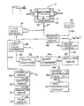
- Fig. 4 is a block diagram of the present invention.
- Fig. 5 shows a correlation of the scan control voltage versus stream temperature as measured by a conventional temperature sensor.
- Fig. 6 is a schematic wiring diagram of the scan rate control circuitry of the present invention.
- A conventional line scan camera, such as a Reticon LC 600 U 1024 Line Scan Camera, sold by the Reticon Corporation, Sunnyvale, CA, uses a lens to focus energy or light from an energy or light emitting "target" or a light source onto a plurality of sensors or photodiodes which are arranged in a predetermined array. When exposed to the light emanating from the targeted light source, a photodiode will generate a voltage that is proportional to the intensity of the sensed light and to the length of time the diode is exposed to the light of the target, i.e., the exposure time. As the light intensity of the target and exposure time increases, the voltage produced by the diode increases.
- Periodically (at a fixed time interval or scan rate) a scanning mechanism in the camera sequentially "reads" the voltage generated by each photodiode. The voltage from each diode may be further processed in a conventional manner and displayed either visually on a cathode ray tube (CRT) or printed. The voltage output of each diode may be used to obtain an indication of the width of the light source, as in the Houston patent, referenced above. However, the results of the use of a conventional unmodified line scan camera to determine the mass flow rate of a free falling molten stream of material have not been satisfactory to date as was alluded to above and as will be explained presently in greater detail.
- Fig. 1 illustrates the relationship between the voltage generated by a photodiode (vd) and the intensity (L) of light from a target or a light source. As can be seen, there is a linear relationship between vd and L up to a certain voltage (vs) which is defined as the "saturation voltage". When a photodiode approaches saturation, the output generated by the photodiode tends to respond non-linearly relative to an increase in L. Typically, the photodiodes in a conventional line scan camera are saturated in order to insure that enough light can be sensed by the photodiodes. As will be seen, the fact that the photodiodes are saturated amplifies certain problems associated with measuring the width and thus the mass flow rate of a moving mass of material such as a free falling molten stream of material.
- As was alluded to above, the existence of several phenomena prevent an unmodified conventional line scan camera, operating near the saturation point of the photodiodes within the camera, from accurately estimating the width of a light source or a free falling stream of molten material. These phenomena are: (1) fluctuations in brightness of the molten stream; (2) stream edge effects; (3) camera lens focusing limitations; (4) camera internal fringing effects and (5) smoke and other spurious images.
- The stream of molten material, falling by means of gravity from an overhead source of the molten material, is incandescent. Hence, it emits energy in the form of light. The light image of the stream comprises visible and infrared light which is not uniform across the width of the molten stream. Additionally, the temperature and thus the light intensity of the molten stream varies with time as the operating conditions of the source changes. Even though the temperature of the molten material may change, the width of the stream may not change. The non-uniform temperature and light intensity distribution across the width of a molten stream occurs because the exterior of the stream is more rapidly cooled by the ambient environment than the stream interior. Hence, the center of the stream appears to be hotter than the stream exterior. In conjunction with this, light emanating radially from the molten stream causes the image of the light intensity of the stream to appear rounded thereby decreasing the apparent width of the stream and altering the stream image to such an extent that the boundaries of the molten stream image do not appear vertical.
- The image of the molten stream is further degraded by focusing limitations of the lens of most cameras. While line scan cameras are sensitive to both the visible and infrared light emanating from the target light source, i.e, the molten stream of material, a normal lens does not focus both of these light wave lengths in the same manner. Therefore, the lens of the camera causes either the infrared or the visible light to be out of focus on the photodiodes resulting in a further degradation of the sensed image. Most common lens filters are ineffective since they become transparent at infrared wave lengths. A filter that may protect the camera from infrared light still does not provide information necessary to determine whether the image of the stream appears rounded because of edge effects or limitations in the lens of the camera.
- Fringing effects within a line scan camera also degrade the image of the light source to be measured. Oncoming light entering a line scan camera is reflected not only by the photodiodes measuring the light intensity of the light source or molten stream but by other structure present within the camera. With this scattering of light or fringing, an inaccurate light intensity reading may be recorded by a photodiode.
- Vapors or smoke produced by the molten stream of material tend to diffuse light emanating from the molten material. While smoke is more of a problem with molten glass materials as compared to other materials such as molten refractory materials, it is still a source of image degradation which must be recognized and accounted for in the measurement process. Finally, other spurious images such as random reflections and ambient lights also contribute in a minor way to the degradation of the measured image of the molten stream.
- All of these phenomena are affected to a greater or lesser degree by the temperature of the molten stream of material. Thus the net effect is that when the stream temperature varies the number of photodiodes activated increases beyond the true number of photodiodes that should be activated. Therefore, the camera cannot and does not measure the true width of a molten stream of material. During recent tests twice the number of photodiodes in an unmodified line scan camera were activated compared to the number of photodiodes activated by a line scan camera modified in accordance with the principles of the present invention.
- An experiment was conducted to confirm the theory that the temperature of the stream affects the degradation of a measurement of the stream width by a line scan camera and thus its ability to measure that width. Fig. 2 illustrates the results of this experiment. In the experiment, a 100-watt light bulb was used as a light source representing the molten stream. Since in practice the molten stream will vary in temperature and thus in light intensity, the light intensity of the bulb was varied by increasing the voltage on the light bulb. The "width" of the light bulb was defined by separating two steel plates by an arbitrary but fixed distance. The light bulb was disposed on one side of the plates behind the defined separation and an unmodified line scan camera was disposed on the other side of the plates and focused on the light bulb. As curve A of Fig. 2 shows, when the voltage on the light bulb increased and thus its light intensity, the measured width ("width squared") increased for an unmodified line scan camera having a fixed scan rate despite the fact that the actual image width of the light bulb was fixed by the steel plates. Curve B in Fig. 2 illustrates the measured width of a light bulb using a modified line scan camera as in the present invention. The correct width of the light bulb as shown in curve B can be measured by a presently modified line scan camera despite great changes in light intensity (temperature) of the light source (molten stream).
- Saturating the photodiodes of an unmodified line scan camera can conceal the effects temperature has on the measurement of the width of a molten stream using that line scan camera. Figs. 3A, 3B, 3C and 3D illustrate this problem. These Figures show diode voltage readings versus a length; in these cases stream width for a low temperature stream (Figs. 3A and 3C) and a high temperature stream (Figs. 3B and 3D). In all instances, it is presumed that the stream is round and is of a constant diameter and that the width of the stream is measured at a constant voltage, i.e., vm. The voltage vm was shown in practice as approximately 1/2 the saturation voltage because it allowed a good area of resolution. Figs. 3A and 3B represent the data obtainable from a conventional line scan camera where the diodes are saturated at a fixed voltage limit, e.g., 5 volts. Figs. 3C and 3D represent the data obtainable from a camera which has no voltage limitations on the diodes.
- Comparing the figures, it can be seen that as temperature increases, the width measured increases (i.e., wmo to wm) in contrast to what should be measured, i.e. the true width (wt). The upper portion of the image is concealed in Figs. 3A and 3B due to saturation of the diodes, while in Figs. 3C and 3D the full extent of the problem may be ascertained.
- In Fig. 3C the "true width", wt, is hidden by the temperature effects of the molten stream which are represented by the shaded sections of the curve. As the molten stream temperature increases, as in Fig. 3D, these effects also increase as seen by the increased area of the shaded section of the curve. In fact, Fig. 3A and 3B graphically illustrate that the effects of temperature are magnified more greatly in a line scan camera having a fixed voltage level and operated at the saturation point of its diodes.
- Figs. 3A, 3B, 3C and 3D represent the temperature effects on a typical line scan camera having a fixed scan rate. The present invention proposes to scale the image of the stream to a fixed light intensity (i.e., "normalize" the stream image) and measure the width of the stream image at an arbitrary but fixed voltage level by varying the scan rate of the camera and thus the exposure time of the diodes. Usually the fixed voltage level or first value is about 80-90% of the saturation voltage of the selected line scan camera. While the width of a normalized stream image measured as in the present invention does not reflect a true width because of the problems mentioned earlier, the width is in error by a constant and can be accounted for by calibration of the present system.
- The present invention may be construed as constituting an automatic gain control for a conventional line scan camera. The present invention should not, however, be understood as being restricted or limited for use with line scan cameras. The invention will work equally as well as an automatic gain control for any camera having a multitude of sensors arranged in a predetermined array or a matrix.
- Fig. 4 generally illustrates the operation of the present invention with respect to an electric furnace. However, the present invention should be considered as being useful in determining the temperature and/or mass flow rate of any moving mass which is emanating from the source of that mass.
- Although the source of the mass is shown in Fig. 4 as a
furnace 10, the source c""'d be any container, including, e.g., a bushing used to filamentize molten material. Thefurnace 10, whr could be heated by gas or electricity, is shown, in the preferred embodiment, as an electric furnace and is used as a source of a mass ofmolten material 12. Thefurnace 10 which is of a conventional design, may have ametal lining 14 such as a platinum/rhodium alloy and may be heated by its own resistance by passing a current through a plurality oflugs 16 which are conductively connected to thelining 14. Athermal insulation layer 18 may surround themetal lining 14. Any material capable of being melted may be melted in thefurnace 10 or thefurnace 10 can be used to further heat or reheat the previously melted material. - Molten material fed out of the furnace through an
outlet orifice 20, controllable by any conventional means, not shown, falls by gravity as a freely fallingstream 22. It is usually desirable to control the temperature of thestream 22 by adjusting the amount of current fed to thelugs 16. Additionally, the mass flow rate or pour rate of thefurnace 10 may be controlled by varying the temperature of themolten material 12 or by adjusting theoutlet orifice 20. To accomplish this for a closed loop control system, it is necessary to continuously measure the temperature and/or mass flow rate of thestream 22. - This is accomplished in the present invention by fixedly positioning a conventional
line scan camera 24 proximate thestream 22 so that at least some of the sensors or photodiodes (not shown) of the camera are exposed to the light intensity of the light emanating from thestream 22. Theline scan camera 24 is positioned to take advantage of the most effective use of the photodiodes of the camera. After the scanning mechanism (not shown) of the camera has measured thevoltages 26 produced on the photodiodes exposed to the light intensity of thestream 22, alight level comparator 28 found in conventional line scan cameras determines whether any of the diodes has produced an output voltage above an arbitrary but fixed voltage level or a first value, i.e., v↑. Usually the light level comparator of an unmodified line scan camera is used to check for an adequate amount of light for accurate readings. However, in the present invention, the light level comparator is used to compare the voltages of the photodiodes with the arbitrary but fixed voltage level. This level is selected to be above the noise contributed by the effects noted above, but below the voltage level at which the diodes are saturated. A stable voltage level has been found to be 80 to 90 percent of the saturation level of the photodiodes of a chosen line scan camera. - After the
light level comparator 28 has compared the voltages read on the diodes by the scanning mechanism to the predetermined voltage level, v1, itsoutput 30 is further processed by asignal conditioner 32 which ensures that a suitablewave form output 34 is passed to anerror integrator 36. - The
error integrator 36 ramps theoutput voltage 34 up or down depending on thevoltage 34 of thesignal conditioner 32. Theintegrator 36 sends an increasing or decreasingvoltage output 38 to a voltage control oscillator means 40. The oscillator means 40 sends ascan start pulse 42 to the camera, i.e., to the external scan starting means 48 of the camera, to cause the scanning mechanism of the camera to begin reading the voltages on the photodiodes. Thepulse 42 is given a phase correction by ameans 44 which hasoutputs 46 or 46'that are sent to themeans 48. Aclock 50, forming a part of thecamera 24 feeds a series ofvoltage pulses 52 to the external scan starting means 48 to cause the photodiodes to be measured by the- camera scanning mechanism when themeans 48 receives a phase correctedsignal 46 or 46'. If the line scan camera chosen does not have provisions for an external scan starting means or provisions for externally modifying the scan rate of the camera, then the camera chosen should be adapted to incorporate this feature. - The
output voltage 38 of theerror integrator 36 may be further processed by obtaining anoutput 54 and correlated by ameans 56 to the temperature of thestream 22 being measured by theline scan camera 24. Optionally, a peak temperature display means 60 may use theoutput 58 of the temperature correlation means 56 to display the maximum temperature of thestream 22. - The temperature correlation means 56 may be a computer which correlates the
voltage 54 to a known voltage-temperature curve such as the one shown in Fig. 5. The data reflected in Fig. 5 was obtained by correlating the voltage 54 (i.e., voltage 38) to the temperature recorded by a conventional temperature sensor, such as an optical pyrometer.. Means 56 can also be a volt meter read by an operator who correlates the voltage reading to data comparable to that illustrated in Fig. 5. Additionally, thevoltage 54 can be run to an analog meter calibrated in terms of temperature units. The calibration would be based on the type of data reflected in Fig. 5. - Mass flow rate measurements may be made by obtaining a signal 64 equivalent to the
voltages 26 and transmitting it to a comparing means 66. The output of each diode is compared by means 66 to a second value, V2, in order to insure that the output of each diode to be counted is above a certain value. The output of the comparing means 66, i.e., signal 68, is read by a counting means 70 which counts the number of diodes having an output above v2. A mass flow rate calculation means 74 computes or generates the mass flow rate based on the number of diodes and sends asignal 76 to a display 78 which may visually display the mass flow rate or may print this information in hard form. - Referring now to Fig. 6, the scan control circuitry of the present invention is illustrated and comprises the
signal conditioner 32, theerror integrator 36, thevoltage control oscillator 40 and the phase correction means 44. - As illustrated, the
signal conditioner 32 comprises an invertor 80 which is connected in series to theoutput 30 of thelight level comparator 28. Theoutput 34 of the invertor 80 is connected to theerror integrator 36 which comprises a plurality ofresistors operational amplifier 90, having aninput 92, and acapacitor 94. Theresistor 84 is connected in series with theoperational amplifier 90 as is theresistor 86 and theresistor 88. Thecapacitor 94 is connected in parallel with the operational amplifier 78. - The
voltage output 38 of theerror integrator 36 is connected to the voltage control oscillator means 40 which comprises aresistor 96 connected in series with a voltage control oscillator 98, while aresistor 100 and a capacitor 102 is connected in parallel to the oscillator 98. Thevoltage output 42 of the oscillator means 40 is connected in series to the phase correction means 44. - The phase correction means 44 comprises a pair of series connected
invertors outputs 46, 46', respectively. The phase correction means 44 provides asynchronized starting pulse 46 or 46'which is fed to the external scan starting means 48 of thecamera 24. Thepulse 46 or the pulse 46' is necessary in order to have a differential signal which is useful for noise immunity. - In operation, when any photodiode exceeds the predetermined voltage level, v" e.g., 4 volts, as determined by the
comparator 28, theoutput voltage 30 increases. This increased voltage causes theoutput voltage 34 to decrease to a low value, e.g., 0 volts. When theoutput voltage 34 is zero, a slight negative voltage will appear at theinput 92 of theoperational amplifier 90 created byresistor 88. The value of theresistors capacitor 94 are chosen to cause thevoltage output 38 of theamplifier 90 to increase at a certain rate per second (volts per second). - If the output voltage of all the photodiodes is below the predetermined value, v" as determined by the
comparator 28, thecomparator 28 generates alow output 30 which is transmitted to the invertor 80. In response to a low voltage at 30, the invertor 80 produces a relatively high voltage represented by thesignal 34 forcing theinput 92 toamplifier 90 to be positive. Theresistors amplifier 90 force theoutput voltage 38 to go down at a certain voltage per second. - The
output voltage 38 of theerror integrator 36 is used to charge the capacitor 102 through theresistors output voltage 38, the more rapidly the capacitor 102 is charged. When the capacitor 102 reaches a preset voltage which is equivalent to a voltage internal to the oscillator 98, the capacitor 102 discharges its charge through theresistor 100 and causes the oscillator 98 to generate a voltage pulse at 42. - The
pulse 42 is further processed by theinvertors pulse 42 is transmitted to thecamera 24 via 46 or 46' at the proper phase by theinverters - The faster that the capacitor 102 is charged, the more rapidly the scan
start voltage pulse 42 is generated by the oscillator 98. Therefore, as the voltage on theoperational amplifier 90 increases due to the increased light emanating from thestream 22, the charging rate in the capacitor 102 also increases. The increased light or temperature of the stream consequently causes the scanning rate of the camera to increase, thereby "normalizing" the image of thestream 22. - For a normalized stream image, the scanning rate of the camera will be substantially constant. However, as the light intensity of a cooling molten stream decreases, the capacitor 102 will not be charged as rapidly by the
error integrator 36, i.e., theoutput voltage 38 will be decreasing at a certain rate. As a result, the oscillator 98 will decrease the frequency of thescanning start pulse 42 and the scan rate of thecamera 24 will decrease, thereby allowing the photodiodes of the camera to be exposed for a greater length of time to the intensity of the light emanating from thestream 22. - Ifthere is insufficient light in the camera to activate the
comparator 28, theoutput 38 of theamplifier 90 is slowly ramped down by theresistor 86. This decreasingoutput 38 is fed to the voltage control oscillator 98 via the capacitor 102 which concomitantly causes the frequency of the synchronized startingpulse 46 or 46' to be reduced. This reduction of the frequency of the scan rate allows a greater exposure time for the photodiodes of the camera. This process is continued until the exposure of the diodes is adequate to activate thecomparator 28. When thecomparator 28 is initially activated, thevoltage output 38 of theamplifier 90 of theerror integrator 36 is ramped up to increase the scanning frequency. - The process of raising and lowering the scanning frequency in relation to the temperature or light intensity variances of the
stream 22 may occur at a relatively slow rate. This rate of change is controlled by the characteristics of the voltage control oscillator 98 and by a time constant which is a function of the values of theresistors capacitor 94. Consequently, the voltages on the diodes are oscillating slowly above and below the predetermined voltage level v, that is used by thecomparator 28 as the standard against which the voltage on each diode is judged. However, this variation is relatively small and does not materially affect the accuracy of the camera system. - The
average voltage 38 going to the oscillator 98 is adequate to normalize the lig.ht intensity of the image to thestream 22 and can be correlated, using theequivalent voltage 54, to the brightness of thestream 22. Since the brightness of the stream is a function of its temperature, thesignal 54 can be correlated by the conventional means 56 to the temperature of the stream. In the preferred embodiment to the present invention, thevoltage 54, which is equivalent to thevoltage 38 which controls the scan rate of theline scan camera 24, may be transmitted to a conventional volt meter. The volt meter readings can then be correlated to a conventional method presently used to measure temperature, e.g., an optical pyrometer. - As Fig. 5 indicates, the voltage 54 (voltage on the voltage control oscillator 98) can be correlated to the measured temperature of a conventional stream temperature sensor. Optionally, a conventional calibrated analog meter may be used to display the peak temperature of the
stream 22. - To determine the mass flow rate of a molten stream of
material 22, the number of exposed diodes generating at least a minimum voltage V2, is compared using means 66. These diodes are counted using the conventional means 70 within the line scan camera. Assuming that the line scan camera has measured the width or diameter of a completely circular stream, the mass flow rate may be calculated using the expression:
- Mf=mass flow rate
- A=an experimental constant
- B=an experimental constant
- W=number of diodes counted or width of the stream
- A and B are constant if and only if the line scan camera is positioned so that it is exposed to a circular stream several furnace outlet orifice diameters downstream of the initial exit of the
stream 22, i.e., from theorifice 20. The system is calibrated by determining A and B using the standard ladle method of estimating mass flow rates and conventional curve fitting techniques. Furthermore, the camera must be fixedly positioned and the image must be normalized as described above. If thecamera 24 is moved whereby the camera sights or views a different portion of thestream 22, then the image of the stream must again be normalized, i.e., the light intensity measured by all exposed photodiodes must be limited to the predetermined voltage level mentioned above and a new set of constants must be derived. - Table 1, below, indicates the results of a comparison of the mass flow rate measurement from a line scan camera modified using the scan rate control of the present invention with the "actual flow" being measured by the ladle method. As can be seen, the average error was about 3 percent. Much of this error is probably related to timing the ladle under the stream. Typically the ladle was held under the stream for 5 to 15 seconds. Another source of error in the comparison is that a person's timing accuracy is only .2 seconds. Inaccurate weighing could also account for another error. In general, the camera system of the present invention can give a flow rate at least as accurately as the ladle method.


- The
stream 22 of aconventional furnace 10 occasionally wanders out of the viewing range of thecamera 24. This problem can be eliminated by selecting a line scan camera having a sufficient number of sensors or photodiodes. Also at times thestream 22 may be highly discontinuous caused by extremely high stream temperatures or a relatively low mass flow rate. When the stream is significantly discontinuous, a line scan camera modified according to the present invention will tend to indicate a mass flow rate that is lower than a mass flow rate measured by the ladle technique. Stream flow rates in excess of 400 pounds (1 pound=454 g) per hour have been found to be stable and may be satisfactorily measured by the present invention. - The temperature and mass flow measurements obtainable with the present invention are extremely useful. In one case the temperature and/or mass flow rate could be used to control the energy input to the
furnace 10 through thelugs 16. Additionally, the mass flow rate may be useful for controlling the flow size of theadjustable orifice 20. - The present invention is also useful for determining the position of the
stream 22. As the stream wanders, different photodiodes in thecamera 24 are exposed to the light intensity of thestream 22. Using a convention technique, the position of the photodiodes can be correlated to the stream position. Knowing the true location of thestream 22 allows a user of the present invention to accurately position apparatus located downstream of thefurnace 10. For example, a fiber attenuator (not shown) capable of fiberizing thematerial 12 and located downstream of thefurnace 10 may be accurately positioned directly under thestream 22 allowing more uniform fiberization. - The present invention has been premised and the previous discussion has presumed that the cross section of the moving mass or
molten stream 22 can be characterized as being circular. While in theory this is a fair approximation of what is really happening, a closer approximation of the actual molten stream configuration may be obtained by utilizing a plurality of line scan cameras modified as in the present invention. These cameras would be appropriately located around thestream 22 and calibrated, as above. The width measured by the cameras could then be multiplied together to determine the stream area which is related to mass flow rate. - It is to be understood that within the scope of the appended claims the invention may be practiced otherwise than as specifically described.
- What is claimed and desired to be secured by Letters Patents of the United States is:
Claims (20)
Applications Claiming Priority (2)
| Application Number | Priority Date | Filing Date | Title |
|---|---|---|---|
| US06/125,303 US4297893A (en) | 1980-02-27 | 1980-02-27 | Method and apparatus for measuring flow characteristics of moving fluid stream |
| US125303 | 1980-02-27 |
Publications (3)
| Publication Number | Publication Date |
|---|---|
| EP0047265A1 EP0047265A1 (en) | 1982-03-17 |
| EP0047265A4 EP0047265A4 (en) | 1984-11-22 |
| EP0047265B1 true EP0047265B1 (en) | 1987-11-11 |
Family
ID=22419093
Family Applications (1)
| Application Number | Title | Priority Date | Filing Date |
|---|---|---|---|
| EP81900544A Expired EP0047265B1 (en) | 1980-02-27 | 1981-01-30 | Method and apparatus for measuring flow characteristics of a moving fluid stream |
Country Status (8)
| Country | Link |
|---|---|
| US (1) | US4297893A (en) |
| EP (1) | EP0047265B1 (en) |
| JP (1) | JPS57500390A (en) |
| BE (1) | BE887472A (en) |
| CA (1) | CA1145156A (en) |
| DE (1) | DE3176523D1 (en) |
| IT (1) | IT1142295B (en) |
| WO (1) | WO1981002466A1 (en) |
Cited By (1)
| Publication number | Priority date | Publication date | Assignee | Title |
|---|---|---|---|---|
| CN108896125A (en) * | 2018-05-08 | 2018-11-27 | 浙江大学 | A method of the gravity stream volume of two interactions of measurement |
Families Citing this family (12)
| Publication number | Priority date | Publication date | Assignee | Title |
|---|---|---|---|---|
| NZ218558A (en) * | 1985-12-19 | 1989-03-29 | Csr Ltd | Measuring flow rate of a fluid by a weight controlled through-flow container |
| US4737178A (en) * | 1986-10-27 | 1988-04-12 | Owens-Corning Fiberglas Corporation | Method for manufacturing mineral fibers |
| US4812151A (en) * | 1988-04-08 | 1989-03-14 | Owens-Corning Fiberglas Corporation | Viscosity control in the manufacture of mineral fibers |
| US5177607A (en) * | 1990-08-27 | 1993-01-05 | Zexel Corporation | Method and apparatus for measuring velocity of fluid |
| US5170438A (en) * | 1991-03-22 | 1992-12-08 | Graham Fiber Glass Limited | Method and apparatus for determining the flow rate of a viscous fluid stream |
| US5598160A (en) * | 1993-10-14 | 1997-01-28 | Ricoh Company, Ltd. | Signal processing circuit with built-in dynamic range matching |
| JP3600262B2 (en) * | 1994-03-04 | 2004-12-15 | 月島機械株式会社 | Measuring device for slag flow rate and furnace equipment using the same |
| US5694480A (en) * | 1995-08-30 | 1997-12-02 | Tsukishima Kikai Co., Ltd. | Molten slag flow rate measuring device and furnace facilities using the same |
| US6289258B1 (en) * | 1998-12-28 | 2001-09-11 | General Electric Company | Drain flowrate measurement |
| FI114414B (en) | 1999-05-05 | 2004-10-15 | Outokumpu Oy | Method and apparatus for monitoring and analyzing foamed surface |
| DE102007043199A1 (en) | 2007-09-11 | 2009-03-12 | Gühring Ohg | Test device for a minimum quantity lubrication system and method for testing a minimum quantity lubrication system |
| EP2574601A1 (en) | 2011-09-30 | 2013-04-03 | Rockwool International A/S | A method and an apparatus for measuring temperature of a fluid stream |
Family Cites Families (3)
| Publication number | Priority date | Publication date | Assignee | Title |
|---|---|---|---|---|
| BE631568A (en) * | 1962-04-27 | |||
| US4090241A (en) * | 1975-12-15 | 1978-05-16 | Owens-Corning Fiberglas Corporation | Method for estimating and controlling the mass flow rate of a free falling fluid stream |
| US4160599A (en) * | 1977-12-08 | 1979-07-10 | Universal Technology, Inc. | Optical gaging system |
-
1980
- 1980-02-27 US US06/125,303 patent/US4297893A/en not_active Expired - Lifetime
-
1981
- 1981-01-30 WO PCT/US1981/000154 patent/WO1981002466A1/en not_active Ceased
- 1981-01-30 DE DE8181900544T patent/DE3176523D1/en not_active Expired
- 1981-01-30 JP JP56500791A patent/JPS57500390A/ja active Pending
- 1981-01-30 EP EP81900544A patent/EP0047265B1/en not_active Expired
- 1981-02-06 IT IT47747/81A patent/IT1142295B/en active
- 1981-02-11 BE BE0/203766A patent/BE887472A/en not_active IP Right Cessation
- 1981-02-26 CA CA000371759A patent/CA1145156A/en not_active Expired
Cited By (1)
| Publication number | Priority date | Publication date | Assignee | Title |
|---|---|---|---|---|
| CN108896125A (en) * | 2018-05-08 | 2018-11-27 | 浙江大学 | A method of the gravity stream volume of two interactions of measurement |
Also Published As
| Publication number | Publication date |
|---|---|
| EP0047265A1 (en) | 1982-03-17 |
| DE3176523D1 (en) | 1987-12-17 |
| JPS57500390A (en) | 1982-03-04 |
| US4297893A (en) | 1981-11-03 |
| WO1981002466A1 (en) | 1981-09-03 |
| IT8147747A0 (en) | 1981-02-06 |
| EP0047265A4 (en) | 1984-11-22 |
| CA1145156A (en) | 1983-04-26 |
| BE887472A (en) | 1981-08-11 |
| IT1142295B (en) | 1986-10-08 |
Similar Documents
| Publication | Publication Date | Title |
|---|---|---|
| US4297893A (en) | Method and apparatus for measuring flow characteristics of moving fluid stream | |
| US6139180A (en) | Method and system for testing the accuracy of a thermocouple probe used to measure the temperature of molten steel | |
| CA2155618C (en) | Method for regulating the furnace in incineration plants, in particular in refuse incineration plants | |
| JP4363769B2 (en) | Method for detecting particles in a tobacco leaf particle stream | |
| US7938576B1 (en) | Sensing system for obtaining images and surface temperatures | |
| NL8103499A (en) | DEVICE FOR MEASURING SURFACE TEMPERATURE. | |
| US4210192A (en) | Automatically controlled pouring method and apparatus for metal casting | |
| WO1999024802A1 (en) | Measuring decay-time constant of fluorescing phosphors | |
| CA1167632A (en) | Method and apparatus for monitoring the diameter of fibers | |
| JP2799290B2 (en) | Pocket-sized laser power meter | |
| US4033697A (en) | Automatic exposure control for a luminous object monitor system | |
| EP0165065A2 (en) | Method and apparatus for non-contact temperature measurement of a static or moving target | |
| US4432657A (en) | Pyrometer method for measuring slab temperature in a reheat furnace | |
| JPS6219727A (en) | Immersion thermometer for molten metal | |
| US3630085A (en) | Apparatus for measuring temperatures | |
| Barker et al. | Supersonic velocimetry in a shock tube using laser enhanced ionisation and planar laser induced fluorescence | |
| US20130042991A1 (en) | Apparatus for detecting and displaying varying levels of a metal melt | |
| RU2109259C1 (en) | Method of gas pressure checking in fuel element of nuclear reactor | |
| US2695364A (en) | Pyrometer | |
| US3426968A (en) | Pyrometer and control of manufacturing processes therewith | |
| JP2023104890A (en) | Liquid level measuring device | |
| JP2004109023A (en) | Temperature measuring method and temperature measuring device for steel surface | |
| JP2023120491A (en) | Radiation thermometer calibration method and calibration device | |
| JPH0848529A (en) | Flow controller for molten optical glass | |
| JP2584621B2 (en) | Method for measuring surface temperature of steel |
Legal Events
| Date | Code | Title | Description |
|---|---|---|---|
| PUAI | Public reference made under article 153(3) epc to a published international application that has entered the european phase |
Free format text: ORIGINAL CODE: 0009012 |
|
| 17P | Request for examination filed |
Effective date: 19811114 |
|
| AK | Designated contracting states |
Designated state(s): DE FR GB NL |
|
| 17Q | First examination report despatched |
Effective date: 19860407 |
|
| GRAA | (expected) grant |
Free format text: ORIGINAL CODE: 0009210 |
|
| AK | Designated contracting states |
Kind code of ref document: B1 Designated state(s): DE FR GB NL |
|
| PG25 | Lapsed in a contracting state [announced via postgrant information from national office to epo] |
Ref country code: FR Free format text: THE PATENT HAS BEEN ANNULLED BY A DECISION OF A NATIONAL AUTHORITY Effective date: 19871111 |
|
| REF | Corresponds to: |
Ref document number: 3176523 Country of ref document: DE Date of ref document: 19871217 |
|
| EN | Fr: translation not filed | ||
| PG25 | Lapsed in a contracting state [announced via postgrant information from national office to epo] |
Ref country code: NL Effective date: 19880801 |
|
| PLBE | No opposition filed within time limit |
Free format text: ORIGINAL CODE: 0009261 |
|
| STAA | Information on the status of an ep patent application or granted ep patent |
Free format text: STATUS: NO OPPOSITION FILED WITHIN TIME LIMIT |
|
| NLV4 | Nl: lapsed or anulled due to non-payment of the annual fee | ||
| GBPC | Gb: european patent ceased through non-payment of renewal fee | ||
| PG25 | Lapsed in a contracting state [announced via postgrant information from national office to epo] |
Ref country code: DE Effective date: 19881001 |
|
| 26N | No opposition filed | ||
| PG25 | Lapsed in a contracting state [announced via postgrant information from national office to epo] |
Ref country code: GB Free format text: LAPSE BECAUSE OF NON-PAYMENT OF DUE FEES Effective date: 19881118 |