EP0047074A2 - Composite springs - Google Patents
Composite springs Download PDFInfo
- Publication number
- EP0047074A2 EP0047074A2 EP81303636A EP81303636A EP0047074A2 EP 0047074 A2 EP0047074 A2 EP 0047074A2 EP 81303636 A EP81303636 A EP 81303636A EP 81303636 A EP81303636 A EP 81303636A EP 0047074 A2 EP0047074 A2 EP 0047074A2
- Authority
- EP
- European Patent Office
- Prior art keywords
- spring
- component
- fibres
- core portion
- locating member
- Prior art date
- Legal status (The legal status is an assumption and is not a legal conclusion. Google has not performed a legal analysis and makes no representation as to the accuracy of the status listed.)
- Granted
Links
Images
Classifications
-
- B—PERFORMING OPERATIONS; TRANSPORTING
- B60—VEHICLES IN GENERAL
- B60G—VEHICLE SUSPENSION ARRANGEMENTS
- B60G11/00—Resilient suspensions characterised by arrangement, location or kind of springs
- B60G11/02—Resilient suspensions characterised by arrangement, location or kind of springs having leaf springs only
- B60G11/04—Resilient suspensions characterised by arrangement, location or kind of springs having leaf springs only arranged substantially parallel to the longitudinal axis of the vehicle
-
- B—PERFORMING OPERATIONS; TRANSPORTING
- B60—VEHICLES IN GENERAL
- B60G—VEHICLE SUSPENSION ARRANGEMENTS
- B60G11/00—Resilient suspensions characterised by arrangement, location or kind of springs
- B60G11/02—Resilient suspensions characterised by arrangement, location or kind of springs having leaf springs only
- B60G11/10—Resilient suspensions characterised by arrangement, location or kind of springs having leaf springs only characterised by means specially adapted for attaching the spring to axle or sprung part of the vehicle
- B60G11/113—Mountings on the axle
-
- F—MECHANICAL ENGINEERING; LIGHTING; HEATING; WEAPONS; BLASTING
- F16—ENGINEERING ELEMENTS AND UNITS; GENERAL MEASURES FOR PRODUCING AND MAINTAINING EFFECTIVE FUNCTIONING OF MACHINES OR INSTALLATIONS; THERMAL INSULATION IN GENERAL
- F16F—SPRINGS; SHOCK-ABSORBERS; MEANS FOR DAMPING VIBRATION
- F16F1/00—Springs
- F16F1/36—Springs made of rubber or other material having high internal friction, e.g. thermoplastic elastomers
- F16F1/366—Springs made of rubber or other material having high internal friction, e.g. thermoplastic elastomers made of fibre-reinforced plastics, i.e. characterised by their special construction from such materials
- F16F1/368—Leaf springs
- F16F1/3683—Attachments or mountings therefor
-
- B—PERFORMING OPERATIONS; TRANSPORTING
- B60—VEHICLES IN GENERAL
- B60G—VEHICLE SUSPENSION ARRANGEMENTS
- B60G2202/00—Indexing codes relating to the type of spring, damper or actuator
- B60G2202/10—Type of spring
- B60G2202/11—Leaf spring
- B60G2202/112—Leaf spring longitudinally arranged
-
- B—PERFORMING OPERATIONS; TRANSPORTING
- B60—VEHICLES IN GENERAL
- B60G—VEHICLE SUSPENSION ARRANGEMENTS
- B60G2204/00—Indexing codes related to suspensions per se or to auxiliary parts
- B60G2204/40—Auxiliary suspension parts; Adjustment of suspensions
- B60G2204/43—Fittings, brackets or knuckles
- B60G2204/4306—Bracket or knuckle for rigid axles, e.g. for clamping
-
- B—PERFORMING OPERATIONS; TRANSPORTING
- B60—VEHICLES IN GENERAL
- B60G—VEHICLE SUSPENSION ARRANGEMENTS
- B60G2204/00—Indexing codes related to suspensions per se or to auxiliary parts
- B60G2204/40—Auxiliary suspension parts; Adjustment of suspensions
- B60G2204/44—Centering or positioning means
- B60G2204/4402—Spacers or shims
Definitions
- This invention relates to leaf springs made of fibre reinforced composite material, comprising layers of fibres at least the majority of which extend longitudinally of the spring spaced from one another in the direction of bending of the spring by a core portion of randomly oriented fibres, all the fibres being set in a resin material.
- leaf springs will hereinafter be referred to as leaf springs of the kind specified.
- the invention relates to the securing to a spring of the kind specified, in the central region thereof, of a component such as a vehicle axle.
- a spring of the kind specified, in the central region thereof, of a component such as a vehicle axle.
- the properties of such a spring depend, inter alia on the longitudinally extending fibres thereof not being interrupted by whatever expedient is used to attach the component to the spring.
- an assembly comprising a leaf spring of the kind specified, a component secured thereto by clamping means at least partially embracing the spring, and a locating member engaging with a formation extending at least partially through the core portion of the spring, said locating member also engaging the component and/or clamping means to prevent movement of the component longitudinally of the spring.
- the locating member may comprise a plate extending across the width of the spring and having upstanding lugs which lie against the sides of the spring, a bolt passing through said lugs and the core portion of the spring.
- the plate may have a formation which engages the component to be attached to the spring.
- the clamping means may comprise U-bolts.
- An alternative form of locating member, in the form of a plate, provided at each side of the spring, may fit between the U-bolts.
- the assembly there illustrated comprises a leaf spring 10 which has spaced layers 11, 12 of fibres the majority of which extend longitudinally of the spring and a core portion 13 of randomly oriented fibres. All the fibres are set in a matrix of a cured resin material, e.g. an epoxy resin, and in one construction of such a spring proposed hitherto the fibres which are longitudinally oriented may be wholly or partly carbon fibres while the fibres in the core portion are glass fibres.
- a cured resin material e.g. an epoxy resin
- An axle beam 14 is secured to the spring by U shape clamping bolts 15, 16 which embrace the spring. On the upper surface of the spring these bolts clamp to the spring a sheet metal component 17 which carries a bump stop 18, and a spacer 19. Between the axle beam 14 and the lower surface of the spring 10 is interposed a wedge shaped element 20 which provides for a desired orientation of the axle beam relative to the spring.
- each side of the spring 10 is secured a locating plate 21, by a bolt 22 extending transversly through an aperture in the core portion 13 of the spring.
- the plates 22 are a close fit between the U bolts 15, 16, and thus prevent undesired movement of the axle beam longitudinally of the spring.
- a locating member is provided in the form of a plate 31 with upwardly extending lugs 32 which lie against the sides of the spring.
- a bolt not shown, is passed through the lugs 32 and the core portion of the spring to secure the locating member to the spring.
- An axle beam is clamped to the spring by U shaped bolts as in Figure 1 or any suitable alternative clamping means, and a dowel peg 33 on the underside of the locating member engages the axle beam to prevent movement of the latter longitudinally of the spring.
- the clamping means takes no part in longitudinal location of the axle beam relative to the spring.
- the spring is of a rectangular shape in cross section, having sharp corners, spacing washers may be disposed between the lugs 32 and the sides of the spring. This is because a plate 31, which normally will be made by bending sheet metal, cannot be formed with a sharp right angled section in the internal angle between the lugs 32 and flat part of the plate 31. If the corners of the spring, as viewed in cross section, are rounded, both the plate 31 and lugs 32 may lie closely against the spring.
Abstract
Description
- This invention relates to leaf springs made of fibre reinforced composite material, comprising layers of fibres at least the majority of which extend longitudinally of the spring spaced from one another in the direction of bending of the spring by a core portion of randomly oriented fibres, all the fibres being set in a resin material. Such leaf springs will hereinafter be referred to as leaf springs of the kind specified.
- More particularly, the invention relates to the securing to a spring of the kind specified, in the central region thereof, of a component such as a vehicle axle. The properties of such a spring depend, inter alia on the longitudinally extending fibres thereof not being interrupted by whatever expedient is used to attach the component to the spring.
- According to the present invention, we provide an assembly comprising a leaf spring of the kind specified, a component secured thereto by clamping means at least partially embracing the spring, and a locating member engaging with a formation extending at least partially through the core portion of the spring, said locating member also engaging the component and/or clamping means to prevent movement of the component longitudinally of the spring.
- It has been found that the properties of a spring of the kind specified are not adversely affected by the provision of a bore or other formation extending transversly through the core portion of the spring, since the longitudinally extending fibres remain unaffected thereby. The use of such a formation to provide for location of the component which is secured to the spring by the clamp means thus is an improvement upon any construction utilising bolts or the like penetrating the spring in its primary direction of bending.
- The locating member may comprise a plate extending across the width of the spring and having upstanding lugs which lie against the sides of the spring, a bolt passing through said lugs and the core portion of the spring. The plate may have a formation which engages the component to be attached to the spring.
- The clamping means may comprise U-bolts. An alternative form of locating member, in the form of a plate, provided at each side of the spring, may fit between the U-bolts.
- These and other features of the invention will now be described by way of example with reference to the accompanying drawings, of which
- Figure 1 is a side elevation of one form of assembly according to the invention.
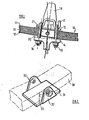
- Figure 2 is a perspective view of part of a further embodiment of the invention.
- Referring firstly to Figure 1, the assembly there illustrated comprises a
leaf spring 10 which has spacedlayers 11, 12 of fibres the majority of which extend longitudinally of the spring and acore portion 13 of randomly oriented fibres. All the fibres are set in a matrix of a cured resin material, e.g. an epoxy resin, and in one construction of such a spring proposed hitherto the fibres which are longitudinally oriented may be wholly or partly carbon fibres while the fibres in the core portion are glass fibres. - An
axle beam 14 is secured to the spring by Ushape clamping bolts bump stop 18, and aspacer 19. Between theaxle beam 14 and the lower surface of thespring 10 is interposed a wedgeshaped element 20 which provides for a desired orientation of the axle beam relative to the spring. - If the axle beam were to be required to lie against the spring, the wedge-
shaped element 20 would be omitted. - To each side of the
spring 10 is secured a locatingplate 21, by abolt 22 extending transversly through an aperture in thecore portion 13 of the spring. Theplates 22 are a close fit between theU bolts - Referring now to Figure 2, there is illustrated in outline only a
spring 30. A locating member is provided in the form of aplate 31 with upwardly extendinglugs 32 which lie against the sides of the spring. A bolt, not shown, is passed through thelugs 32 and the core portion of the spring to secure the locating member to the spring. An axle beam is clamped to the spring by U shaped bolts as in Figure 1 or any suitable alternative clamping means, and adowel peg 33 on the underside of the locating member engages the axle beam to prevent movement of the latter longitudinally of the spring. In this case, the clamping means takes no part in longitudinal location of the axle beam relative to the spring. - If the spring is of a rectangular shape in cross section, having sharp corners, spacing washers may be disposed between the
lugs 32 and the sides of the spring. This is because aplate 31, which normally will be made by bending sheet metal, cannot be formed with a sharp right angled section in the internal angle between thelugs 32 and flat part of theplate 31. If the corners of the spring, as viewed in cross section, are rounded, both theplate 31 andlugs 32 may lie closely against the spring. - In this embodiment also there may be provided one or more spacers between the actual beam and the spring, or, if required, a wedge shaped element as shown in Figure 1.
- Although the particular embodiment described above is the securing of an axle beam to a spring, it will be appreciated that the invention is applicable to the securing of other components to a spring where similar or analogous conditions apply.
Claims (7)
Priority Applications (1)
| Application Number | Priority Date | Filing Date | Title |
|---|---|---|---|
| AT81303636T ATE7772T1 (en) | 1980-08-30 | 1981-08-10 | LAYER FEATHERS. |
Applications Claiming Priority (2)
| Application Number | Priority Date | Filing Date | Title |
|---|---|---|---|
| GB8028102 | 1980-08-30 | ||
| GB8028102 | 1980-08-30 |
Publications (3)
| Publication Number | Publication Date |
|---|---|
| EP0047074A2 true EP0047074A2 (en) | 1982-03-10 |
| EP0047074A3 EP0047074A3 (en) | 1982-05-26 |
| EP0047074B1 EP0047074B1 (en) | 1984-06-06 |
Family
ID=10515750
Family Applications (1)
| Application Number | Title | Priority Date | Filing Date |
|---|---|---|---|
| EP81303636A Expired EP0047074B1 (en) | 1980-08-30 | 1981-08-10 | Composite springs |
Country Status (11)
| Country | Link |
|---|---|
| EP (1) | EP0047074B1 (en) |
| JP (1) | JPS57107909A (en) |
| AT (1) | ATE7772T1 (en) |
| AU (1) | AU547943B2 (en) |
| BR (1) | BR8105465A (en) |
| CA (1) | CA1181775A (en) |
| DE (1) | DE3163985D1 (en) |
| DK (1) | DK375581A (en) |
| ES (1) | ES505030A0 (en) |
| IE (1) | IE51513B1 (en) |
| ZA (1) | ZA815589B (en) |
Cited By (8)
| Publication number | Priority date | Publication date | Assignee | Title |
|---|---|---|---|---|
| EP0092949A2 (en) * | 1982-04-23 | 1983-11-02 | Rubery Owen Holdings Limited | Leaf spring assemblies |
| DE3532297C1 (en) * | 1985-09-11 | 1987-04-23 | Arbed Techno Gmbh | Fiber-reinforced plastic leaf spring |
| US4771997A (en) * | 1986-04-24 | 1988-09-20 | Audi Ag | Motor vehicle fiber-reinforced synthetic material leaf spring or transverse link with end clamp/power-induction unit |
| US5194111A (en) * | 1989-09-14 | 1993-03-16 | Pacific Coast Composites, Inc. | Composite constant stress beam with gradient fiber distribution |
| EP0907860A1 (en) * | 1996-06-28 | 1999-04-14 | The Boler Company. | Means for and method of mounting a suspension member to an axle housing |
| WO2001068389A1 (en) * | 2000-03-14 | 2001-09-20 | Fundiciones De Vera, S.A. | System for fixing a spring to a vehicle axle and spring for a vehicle axle |
| WO2004003403A1 (en) * | 2002-06-27 | 2004-01-08 | Db Cargo Ag | Leaf spring having a plurality of layers made of different high polymer materials |
| EP3456559A1 (en) * | 2017-09-14 | 2019-03-20 | Frauenthal Automotive Sales GmbH | Leaf spring for use in connection with a wheel suspension of a vehicle |
Families Citing this family (1)
| Publication number | Priority date | Publication date | Assignee | Title |
|---|---|---|---|---|
| GB8315704D0 (en) * | 1983-06-08 | 1983-07-13 | Gkn Technology Ltd | Securing components to springs of composite material |
Citations (7)
| Publication number | Priority date | Publication date | Assignee | Title |
|---|---|---|---|---|
| US2643111A (en) * | 1948-07-29 | 1953-06-23 | Gen Motors Corp | Single-leaf spring clamp |
| US3305231A (en) * | 1964-11-16 | 1967-02-21 | Rockwell Standard Co | Vehicle leaf springs |
| US3437333A (en) * | 1966-10-24 | 1969-04-08 | North American Rockwell | Spring seat |
| US3490758A (en) * | 1968-01-12 | 1970-01-20 | Edwin E Foster | Vehicular suspension with prestressed single plate leaf spring |
| FR2102454A5 (en) * | 1970-08-04 | 1972-04-07 | Nord Ressorts | |
| DE2635329A1 (en) * | 1976-08-05 | 1978-02-09 | Brueninghaus Gmbh Stahlwerke | Railway vehicle suspension leaf spring - uses variety of welds for alternative designs of clamping strap around spring stack |
| EP0005916A1 (en) * | 1978-05-26 | 1979-12-12 | GKN Group Services Limited | Spring manufacture |
Family Cites Families (2)
| Publication number | Priority date | Publication date | Assignee | Title |
|---|---|---|---|---|
| JPS534921A (en) * | 1976-07-02 | 1978-01-18 | Nissan Shatai Co | Axle mounting type suspension |
| JPS5570633U (en) * | 1978-11-08 | 1980-05-15 |
-
1981
- 1981-08-10 EP EP81303636A patent/EP0047074B1/en not_active Expired
- 1981-08-10 AT AT81303636T patent/ATE7772T1/en not_active IP Right Cessation
- 1981-08-10 DE DE8181303636T patent/DE3163985D1/en not_active Expired
- 1981-08-12 AU AU74029/81A patent/AU547943B2/en not_active Ceased
- 1981-08-13 ZA ZA815589A patent/ZA815589B/en unknown
- 1981-08-25 DK DK375581A patent/DK375581A/en not_active Application Discontinuation
- 1981-08-27 BR BR8105465A patent/BR8105465A/en unknown
- 1981-08-28 IE IE1975/81A patent/IE51513B1/en unknown
- 1981-08-28 ES ES505030A patent/ES505030A0/en active Granted
- 1981-08-28 CA CA000384780A patent/CA1181775A/en not_active Expired
- 1981-08-31 JP JP56136935A patent/JPS57107909A/en active Granted
Patent Citations (7)
| Publication number | Priority date | Publication date | Assignee | Title |
|---|---|---|---|---|
| US2643111A (en) * | 1948-07-29 | 1953-06-23 | Gen Motors Corp | Single-leaf spring clamp |
| US3305231A (en) * | 1964-11-16 | 1967-02-21 | Rockwell Standard Co | Vehicle leaf springs |
| US3437333A (en) * | 1966-10-24 | 1969-04-08 | North American Rockwell | Spring seat |
| US3490758A (en) * | 1968-01-12 | 1970-01-20 | Edwin E Foster | Vehicular suspension with prestressed single plate leaf spring |
| FR2102454A5 (en) * | 1970-08-04 | 1972-04-07 | Nord Ressorts | |
| DE2635329A1 (en) * | 1976-08-05 | 1978-02-09 | Brueninghaus Gmbh Stahlwerke | Railway vehicle suspension leaf spring - uses variety of welds for alternative designs of clamping strap around spring stack |
| EP0005916A1 (en) * | 1978-05-26 | 1979-12-12 | GKN Group Services Limited | Spring manufacture |
Cited By (11)
| Publication number | Priority date | Publication date | Assignee | Title |
|---|---|---|---|---|
| EP0092949A2 (en) * | 1982-04-23 | 1983-11-02 | Rubery Owen Holdings Limited | Leaf spring assemblies |
| EP0092949B1 (en) * | 1982-04-23 | 1987-08-12 | Rubery Owen Holdings Limited | Leaf spring assemblies |
| DE3532297C1 (en) * | 1985-09-11 | 1987-04-23 | Arbed Techno Gmbh | Fiber-reinforced plastic leaf spring |
| US4771997A (en) * | 1986-04-24 | 1988-09-20 | Audi Ag | Motor vehicle fiber-reinforced synthetic material leaf spring or transverse link with end clamp/power-induction unit |
| US5194111A (en) * | 1989-09-14 | 1993-03-16 | Pacific Coast Composites, Inc. | Composite constant stress beam with gradient fiber distribution |
| EP0907860A1 (en) * | 1996-06-28 | 1999-04-14 | The Boler Company. | Means for and method of mounting a suspension member to an axle housing |
| EP0907860A4 (en) * | 1996-06-28 | 1999-12-01 | Boler Co | Means for and method of mounting a suspension member to an axle housing |
| WO2001068389A1 (en) * | 2000-03-14 | 2001-09-20 | Fundiciones De Vera, S.A. | System for fixing a spring to a vehicle axle and spring for a vehicle axle |
| ES2162597A1 (en) * | 2000-03-14 | 2001-12-16 | Fundiciones De Vera S A | System for fixing a spring to a vehicle axle and spring for a vehicle axle |
| WO2004003403A1 (en) * | 2002-06-27 | 2004-01-08 | Db Cargo Ag | Leaf spring having a plurality of layers made of different high polymer materials |
| EP3456559A1 (en) * | 2017-09-14 | 2019-03-20 | Frauenthal Automotive Sales GmbH | Leaf spring for use in connection with a wheel suspension of a vehicle |
Also Published As
| Publication number | Publication date |
|---|---|
| ZA815589B (en) | 1982-08-25 |
| DE3163985D1 (en) | 1984-07-12 |
| AU547943B2 (en) | 1985-11-14 |
| AU7402981A (en) | 1982-03-11 |
| IE51513B1 (en) | 1987-01-07 |
| EP0047074A3 (en) | 1982-05-26 |
| JPS57107909A (en) | 1982-07-05 |
| ES8205982A1 (en) | 1982-07-01 |
| ATE7772T1 (en) | 1984-06-15 |
| CA1181775A (en) | 1985-01-29 |
| BR8105465A (en) | 1982-05-11 |
| EP0047074B1 (en) | 1984-06-06 |
| IE811975L (en) | 1982-02-28 |
| JPS628326B2 (en) | 1987-02-21 |
| DK375581A (en) | 1982-03-01 |
| ES505030A0 (en) | 1982-07-01 |
Similar Documents
| Publication | Publication Date | Title |
|---|---|---|
| DE2360857C2 (en) | Resilient mount, especially engine mount | |
| KR910005043B1 (en) | Axle clamp | |
| EP0047074B1 (en) | Composite springs | |
| EP0162189B1 (en) | Frp leaf spring, especially for motor vehicles | |
| EP0343891A1 (en) | Attachment of components to composite members | |
| DE102011117746A1 (en) | Bumper device with a mounting aid | |
| EP0130688B1 (en) | Securing components to springs of composite material | |
| US4489922A (en) | Spring leaf comprising pultruded beam | |
| EP0151146B1 (en) | Leaf springs of composite material | |
| DD297608A5 (en) | ELASTIC ATTACHMENT, ESPECIALLY FOR A VEHICLE ENGINE | |
| US4623133A (en) | Clamping devices for spring assemblies | |
| US4080084A (en) | Splicing device for overlapped rods | |
| EP0283318A1 (en) | Assembly including leaf spring of composite material | |
| JPS62160907A (en) | Vehicular suspension device | |
| EP0199667B1 (en) | Resilient pad for steel y-sleepers | |
| DE102017215403B4 (en) | spring assembly | |
| DE102022111753A1 (en) | container holding device | |
| JPH0261669B2 (en) | ||
| EP0012265B1 (en) | Rail fastening apparatus | |
| EP0256007B1 (en) | Securing components to springs of composite material | |
| GB2158548A (en) | Leaf springs of composite material | |
| DE102013205017A1 (en) | Fastening device for fiber composite elements on a support structure | |
| JPS6234038Y2 (en) | ||
| JPS6333015B2 (en) | ||
| DE102020111069A1 (en) | Leaf spring |
Legal Events
| Date | Code | Title | Description |
|---|---|---|---|
| PUAI | Public reference made under article 153(3) epc to a published international application that has entered the european phase |
Free format text: ORIGINAL CODE: 0009012 |
|
| AK | Designated contracting states |
Designated state(s): AT BE CH DE FR GB IT LU NL SE |
|
| PUAL | Search report despatched |
Free format text: ORIGINAL CODE: 0009013 |
|
| AK | Designated contracting states |
Designated state(s): AT BE CH DE FR GB IT LU NL SE |
|
| 17P | Request for examination filed |
Effective date: 19820408 |
|
| ITF | It: translation for a ep patent filed |
Owner name: JACOBACCI & PERANI S.P.A. |
|
| GRAA | (expected) grant |
Free format text: ORIGINAL CODE: 0009210 |
|
| AK | Designated contracting states |
Designated state(s): AT BE CH DE FR GB IT LI LU NL SE |
|
| REF | Corresponds to: |
Ref document number: 7772 Country of ref document: AT Date of ref document: 19840615 Kind code of ref document: T |
|
| REF | Corresponds to: |
Ref document number: 3163985 Country of ref document: DE Date of ref document: 19840712 |
|
| PGFP | Annual fee paid to national office [announced via postgrant information from national office to epo] |
Ref country code: DE Payment date: 19840808 Year of fee payment: 4 |
|
| PGFP | Annual fee paid to national office [announced via postgrant information from national office to epo] |
Ref country code: FR Payment date: 19840809 Year of fee payment: 4 |
|
| ET | Fr: translation filed | ||
| PGFP | Annual fee paid to national office [announced via postgrant information from national office to epo] |
Ref country code: CH Payment date: 19840820 Year of fee payment: 4 |
|
| PG25 | Lapsed in a contracting state [announced via postgrant information from national office to epo] |
Ref country code: LU Free format text: LAPSE BECAUSE OF NON-PAYMENT OF DUE FEES Effective date: 19840831 |
|
| PGFP | Annual fee paid to national office [announced via postgrant information from national office to epo] |
Ref country code: SE Payment date: 19840930 Year of fee payment: 4 Ref country code: BE Payment date: 19840930 Year of fee payment: 4 |
|
| PLBI | Opposition filed |
Free format text: ORIGINAL CODE: 0009260 |
|
| 26 | Opposition filed |
Opponent name: DAIMLER-BENZ AKTIENGESELLSCHAFT Effective date: 19850306 Opponent name: VEREINIGTE EDELSTAHLWERKE AKTIENGESELLSCHAFT (VEW) Effective date: 19850305 |
|
| NLR1 | Nl: opposition has been filed with the epo |
Opponent name: DAIMLER-BENZ AG. Opponent name: VEREINIGTE EDELSTAHLWERKE AG. (VEW) |
|
| PGFP | Annual fee paid to national office [announced via postgrant information from national office to epo] |
Ref country code: AT Payment date: 19860821 Year of fee payment: 6 |
|
| PGFP | Annual fee paid to national office [announced via postgrant information from national office to epo] |
Ref country code: NL Payment date: 19870831 Year of fee payment: 7 |
|
| PG25 | Lapsed in a contracting state [announced via postgrant information from national office to epo] |
Ref country code: SE Effective date: 19880811 |
|
| RDAG | Patent revoked |
Free format text: ORIGINAL CODE: 0009271 |
|
| STAA | Information on the status of an ep patent application or granted ep patent |
Free format text: STATUS: PATENT REVOKED |
|
| 27W | Patent revoked |
Effective date: 19880819 |
|
| REG | Reference to a national code |
Ref country code: CH Ref legal event code: PL |
|
| BERE | Be: lapsed |
Owner name: GKN GROUP SERVICES LTD Effective date: 19880831 |
|
| GBPR | Gb: patent revoked under art. 102 of the ep convention designating the uk as contracting state | ||
| NLR2 | Nl: decision of opposition | ||
| GBPC | Gb: european patent ceased through non-payment of renewal fee | ||
| EUG | Se: european patent has lapsed |
Ref document number: 81303636.5 Effective date: 19890510 |
|
| PLAB | Opposition data, opponent's data or that of the opponent's representative modified |
Free format text: ORIGINAL CODE: 0009299OPPO |