EP0046431A1 - Servo-valve électro-hydraulique - Google Patents
Servo-valve électro-hydraulique Download PDFInfo
- Publication number
- EP0046431A1 EP0046431A1 EP81401279A EP81401279A EP0046431A1 EP 0046431 A1 EP0046431 A1 EP 0046431A1 EP 81401279 A EP81401279 A EP 81401279A EP 81401279 A EP81401279 A EP 81401279A EP 0046431 A1 EP0046431 A1 EP 0046431A1
- Authority
- EP
- European Patent Office
- Prior art keywords
- transducer
- nozzle
- servovalve
- orifice
- piezoelectric
- Prior art date
- Legal status (The legal status is an assumption and is not a legal conclusion. Google has not performed a legal analysis and makes no representation as to the accuracy of the status listed.)
- Ceased
Links
Images

Classifications
-
- F—MECHANICAL ENGINEERING; LIGHTING; HEATING; WEAPONS; BLASTING
- F15—FLUID-PRESSURE ACTUATORS; HYDRAULICS OR PNEUMATICS IN GENERAL
- F15C—FLUID-CIRCUIT ELEMENTS PREDOMINANTLY USED FOR COMPUTING OR CONTROL PURPOSES
- F15C3/00—Circuit elements having moving parts
- F15C3/10—Circuit elements having moving parts using nozzles or jet pipes
- F15C3/14—Circuit elements having moving parts using nozzles or jet pipes the jet the nozzle being intercepted by a flap
-
- F—MECHANICAL ENGINEERING; LIGHTING; HEATING; WEAPONS; BLASTING
- F15—FLUID-PRESSURE ACTUATORS; HYDRAULICS OR PNEUMATICS IN GENERAL
- F15B—SYSTEMS ACTING BY MEANS OF FLUIDS IN GENERAL; FLUID-PRESSURE ACTUATORS, e.g. SERVOMOTORS; DETAILS OF FLUID-PRESSURE SYSTEMS, NOT OTHERWISE PROVIDED FOR
- F15B5/00—Transducers converting variations of physical quantities, e.g. expressed by variations in positions of members, into fluid-pressure variations or vice versa; Varying fluid pressure as a function of variations of a plurality of fluid pressures or variations of other quantities
- F15B5/003—Transducers converting variations of physical quantities, e.g. expressed by variations in positions of members, into fluid-pressure variations or vice versa; Varying fluid pressure as a function of variations of a plurality of fluid pressures or variations of other quantities characterised by variation of the pressure in a nozzle or the like, e.g. nozzle-flapper system
-
- F—MECHANICAL ENGINEERING; LIGHTING; HEATING; WEAPONS; BLASTING
- F16—ENGINEERING ELEMENTS AND UNITS; GENERAL MEASURES FOR PRODUCING AND MAINTAINING EFFECTIVE FUNCTIONING OF MACHINES OR INSTALLATIONS; THERMAL INSULATION IN GENERAL
- F16K—VALVES; TAPS; COCKS; ACTUATING-FLOATS; DEVICES FOR VENTING OR AERATING
- F16K31/00—Actuating devices; Operating means; Releasing devices
- F16K31/004—Actuating devices; Operating means; Releasing devices actuated by piezoelectric means
- F16K31/005—Piezoelectric benders
Definitions
- the present invention relates to an electro-hydraulic servovalve comprising at least one variable throttle controlled by an electrical signal of low power so as to control a hydraulic flow or pressure.
- This servovalve constitutes a single or double hydraulic potentiometer or a variable throttle.
- Variable throttles are widely used in electro-hydraulic servovalves because they allow to modulate either the flow at given pressure drop or to modify the pressure drop at given flow.
- a simple hydraulic potentiometer has only one variable throttle supplied through a fixed throttle at a given pressure and allows the pressure to be modulated on an outlet located between the fixed throttle and the variable throttle.
- a double hydraulic potentiometer which generally constitutes the first stage of a servovalve, combines two variable throttles supplied from a common pressure source, each through a fixed throttle. It modulates the pressures on two outputs each connected between a fixed throttle and a variable throttle.
- Variable throttle of the nozzle-pallet or sprinkler-pallet type is widely used.
- the pallet is moved along the axis of the nozzle so as to vary the distance between the nozzle and the pallet.
- the pallet is moved by a torque motor whose frame oscillates in a plane passing through the axis of the nozzle, the pallet being linked to the frame by a rod.
- a spring returns the pallet to the neutral position.
- This torque motor is a complex and expensive component.
- the present invention relates to a servovalve comprising at least one variable throttle of the nozzle-shutter or sprinkler-vane type controlled by a piezoelectric transducer.
- This servovalve does not require a torque motor, nor a connection between the motor and the shutter, nor a return spring and its price is therefore reduced.
- Variable throttling is achieved by components which do not introduce friction.
- the servovalve according to the invention comprises at least one nozzle fixed in a body and supplied with hydraulic fluid and it is essentially characterized in that it comprises a piezoelectric transducer constituted by at least one elementary transducer formed by a ceramic pellet electric piezo clamped between two electrodes and held in the body facing the orifice of the nozzle, substantially perpendicular to the axis of this nozzle, so that the deformation of the transducer under the action of an electrical signal applied to the electrodes modifies the distance between the orifice of said nozzle and the transducer.
- the servovalve comprises at least one nozzle or nozzle 11 or 12.
- Each nozzle is fixedly mounted in the body 2 and its conical end opens into a chamber 6 formed inside the body.
- Each nozzle 11 or 12 is supplied with hydraulic liquid by a conduit 81 and provides a jet of liquid through its orifice.
- Each variable throttle is formed between a nozzle and a piezoelectric transducer 3 comprising at least one elementary transducer 31 constituted by a piezoelectric ceramic wafer sandwiched between two metal electrodes adjacent to its two plane parallel faces. A potential difference is applied between the electrodes enclosing each pad which ensures a deformation of the transducer.
- Each elementary transducer 31 is held in the body 2 so that the faces of the pellets 31 are substantially perpendicular to the axis of each nozzle 11 or 12.
- Each nozzle 11 or 12 faces, with a clearance, a face 311 of the transducer .
- the deformation of the transducer 3 moves, opposite the jet exiting from each fixed nozzle, a sealing face which remains substantially perpendicular in its displacement to the axis 13 of the nozzle and of the jet. This movement regulates an annular orifice through which the hydraulic fluid flows out of the orifice of the fixed nozzle, from the center to the periphery.
- the leakage rate downstream of the nozzles 11 and 12 is evacuated from the chamber 6 by a pipe 82 from the body.
- the transducer 3 is held in the chamber 6 by an elastic metal membrane 5.
- This membrane of constant thickness preferably has a circular shape and is embedded over its entire periphery in the body 2, between two flat annular bearings.
- the transducer 3 consists of two elementary transducers 31 each consisting of a circular disc, disc-shaped, coated, on both sides, with electrodes. Each patch is centered on the axis 13 of the nozzles.
- the two pads 31 constituting a bimetallic strip are fixed on either side of the membrane 5 which they enclose. They are fixed by gluing or by an equivalent method of fixing, to the membrane.
- the surface 311 of the piezoelectric transducer 3 is smaller than the section of the chamber 6 in a direction parallel to the membrane 5.
- the piezoelectric transducer covers only part of the membrane 5.
- a part of the membrane 5 surrounding the transducer and located inside the embedding of the membrane in the body is not in contact, on both sides, with the transducer 3. This arrangement ensures mechanical amplification.
- the outer faces 311 are separated, with clearances, from the nozzles 11 and 12.
- the piezoelectric axes of the two pads 31 are in the same direction.
- the two electrodes adjacent to the metal membrane 5 are at zero potential.
- potential differences are applied by the conductors 32, 33 connected to the external electrodes 311 of the pads, one of the pads extends parallel to the membrane, while the other pad becomes shorter.
- the bimetallic strip bends.
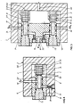
- the servovalve shown in Figure 1 has two nozzles 11 and 12 coaxial with the axis 13 and giving two opposite jets.
- the assembly formed by the membrane 5 and the two pellets 31 is mounted between the two nozzles 11 and 12.
- the nozzles 11 and 12 are mounted respectively in cores 21 and 22 capable of sliding along the axis 13 so as to allow the adjustment of the spacing between the nozzle orifices and the metal membrane 5.
- the membrane is clamped between an annular ring 24 and a core 21.
- Each nozzle is supplied through a constriction 71 or 72 fixed or calibrated.
- the bending of the piezoelectric transducer 3 leads on the one hand to an increase in the distance between one of the nozzles and the membrane and, consequently, to a decrease in the distance between this membrane and the other nozzle.
- the leakage rate through one of the nozzles increases while the leakage rate through the other nozzle decreases. This allows adjustment of the pressure difference between the use outputs 91 and 92 each connected between the orifice of a nozzle and the fixed throttle.
- the servovalve of Figure 2 has only one nozzle 11 supplied through a fixed throttle 71.
- the leakage rate exiting through the nozzle 11 is evacuated from the chamber 6 by the conduit 82.
- the outlet 91 between the fixed throttle 71 and the orifice of the nozzle 11 allows the pressure control.
- the servovalve could be used as a simple throttle, the nozzle 11 being supplied directly without fixed throttling.
- the transducer 3 attached to the membrane 5 consists of a single piezoelectric patch 31 fixed on one side of this membrane.
- the piezoelectric transducer 3 associated with a nozzle 11 or 12 has the form of a bar constituted by a stack of piezoelectric pellets 31.
- Each pellet 31 is constituted by a disc in piezoelectric ceramic coated, on its two parallel faces, with metal electrodes.
- This cylindrical bar is mounted so that its axis is coaxial with the axis of the associated nozzle, the planar faces being perpendicular to the axis of the associated nozzle.
- the end of the bar oriented towards the side of the nozzle is free, the face 312 of the bar opposite the nozzle being fixed in abutment against a bearing surface of the body of the servovalve.
- Each nozzle faces the free flat face of the bar which receives the jet perpendicularly.
- the change in length of the bar by reverse piezoelectric effect modifies the annular leak orifice.
- a conductor 34 connects the electrodes separated by intervals of two pads.
- Another conductor 35 connects the electrodes separated by intervals of two pads.
- one of the electrodes is connected to the conductor 34, the other electrode being connected to the conductor 35.
- Each conductor can be constituted by a strip of copper. You can also use electrical wires bonded to ceramics with a conductive adhesive.
- the servovalve shown in Figure 3 has two nozzles 11 and 12. Each nozzle supplied by a fixed throttle 71 or 72 faces the free end of a bar. The two nozzles are mounted in parallel but can also be mounted coaxially. The use outputs 91 or 92 are each connected between a variable throttle of a nozzle and a fixed throttle 71 or 72.
- the servovalve of Figure 4 has only one nozzle, the orifice of which faces the free end of the bar 3 consisting of a stacking of piezoelectric pellets 31.
- the outlet 91 connected between the orifice of the nozzle and the fixed throttle 71 allows the control of a pressure.
- Each face 311-constituting an electrode-subjected to the jet of hydraulic fluid can be protected by a resistant washer glued or fixed on the piezoelectric pellet.
- a washer 4 is fixed on the face of the pellet 31 located on the side of the nozzle.
- the voltage applied between the electrodes of the pad 31 and the voltage applied between the electrodes of the other pad 31 are equal and opposite.
- the voltages applied between the conductors 34 and 35 of the bars associated with the nozzles 11 and 12 are equal and opposite.
- the resistant washer can be fixed to each pad 31 in the servovalves shown in FIGS. 1 and 2.
Landscapes
- Engineering & Computer Science (AREA)
- General Engineering & Computer Science (AREA)
- Mechanical Engineering (AREA)
- Physics & Mathematics (AREA)
- Fluid Mechanics (AREA)
- Theoretical Computer Science (AREA)
- Servomotors (AREA)
- Supply Devices, Intensifiers, Converters, And Telemotors (AREA)
Applications Claiming Priority (2)
| Application Number | Priority Date | Filing Date | Title |
|---|---|---|---|
| FR8018125A FR2488951A1 (fr) | 1980-08-19 | 1980-08-19 | Servovalve electro-hydraulique |
| FR8018125 | 1980-08-19 |
Publications (1)
| Publication Number | Publication Date |
|---|---|
| EP0046431A1 true EP0046431A1 (fr) | 1982-02-24 |
Family
ID=9245274
Family Applications (1)
| Application Number | Title | Priority Date | Filing Date |
|---|---|---|---|
| EP81401279A Ceased EP0046431A1 (fr) | 1980-08-19 | 1981-08-07 | Servo-valve électro-hydraulique |
Country Status (2)
| Country | Link |
|---|---|
| EP (1) | EP0046431A1 (enExample) |
| FR (1) | FR2488951A1 (enExample) |
Cited By (13)
| Publication number | Priority date | Publication date | Assignee | Title |
|---|---|---|---|---|
| JPS6018307U (ja) * | 1983-07-16 | 1985-02-07 | 株式会社島津製作所 | 圧力制御装置 |
| FR2562200A1 (fr) * | 1984-03-29 | 1985-10-04 | Charron Jean Claude | Micro-electrovalve modulable a tres faible temps de reponse et a tres f |
| GB2175980A (en) * | 1985-05-23 | 1986-12-10 | Moteurs Societe Nationale D Et | Pressure reducer |
| FR2583115A1 (fr) * | 1985-06-10 | 1986-12-12 | Centre Techn Ind Mecanique | Transducteur electrofluidique du type buse/palette et servovalve hydraulique equipee d'un tel transducteur |
| FR2642812A1 (fr) * | 1989-02-08 | 1990-08-10 | Crouzet Sa | Dispositif de commutation de fluide, piezoelectrique a commande optique |
| FR2660084A1 (fr) * | 1990-03-21 | 1991-09-27 | Gilson Med Electr | Systeme de regulation de pression dans un circuit de circulation de fluide a debit determine, et chromatographe utilisant ce systeme. |
| EP0538236A1 (de) * | 1991-09-30 | 1993-04-21 | Hoerbiger Ventilwerke Aktiengesellschaft | Piezo-Ventil |
| WO1996026377A1 (en) * | 1995-02-21 | 1996-08-29 | Applied Power Inc. | Piezo-electrically actuated valve |
| US5630440A (en) * | 1995-02-21 | 1997-05-20 | Applied Power Inc. | Piezo composite sheet actuated valve |
| EP0794370A1 (en) * | 1996-03-08 | 1997-09-10 | Siemens-Elema AB | Valve |
| EP0787899A3 (de) * | 1996-01-30 | 1998-04-08 | Rudolphus Adrianus Jeanne Marie Van Boxel | Geräte zur Regelung des Durchflusses eines Fluidums |
| CN102242743A (zh) * | 2011-07-11 | 2011-11-16 | 南京航空航天大学 | 多喷嘴挡板电液伺服阀及其工作方法 |
| CN111075988A (zh) * | 2019-11-13 | 2020-04-28 | 北京机械设备研究所 | 一种伺服阀自动对中装置及对中方法 |
Citations (5)
| Publication number | Priority date | Publication date | Assignee | Title |
|---|---|---|---|---|
| FR1514669A (fr) * | 1966-10-20 | 1968-02-23 | Fisher Governor Co | Dispositif de réglage de pression |
| GB1206060A (en) * | 1967-10-12 | 1970-09-23 | Heli Coil Corp Controls Divisi | Servo-valve with ceramic force motor |
| GB1217225A (en) * | 1968-05-23 | 1970-12-31 | Automotive Prod Co Ltd | Improvements in or relating to electrically operated valves and fluid-flow directing devices |
| FR2188771A5 (enExample) * | 1972-06-01 | 1974-01-18 | British Oxygen Co Ltd | |
| DE2511752A1 (de) * | 1975-03-18 | 1976-10-07 | Ver Flugtechnische Werke | Signalwandlerstufe |
-
1980
- 1980-08-19 FR FR8018125A patent/FR2488951A1/fr active Granted
-
1981
- 1981-08-07 EP EP81401279A patent/EP0046431A1/fr not_active Ceased
Patent Citations (5)
| Publication number | Priority date | Publication date | Assignee | Title |
|---|---|---|---|---|
| FR1514669A (fr) * | 1966-10-20 | 1968-02-23 | Fisher Governor Co | Dispositif de réglage de pression |
| GB1206060A (en) * | 1967-10-12 | 1970-09-23 | Heli Coil Corp Controls Divisi | Servo-valve with ceramic force motor |
| GB1217225A (en) * | 1968-05-23 | 1970-12-31 | Automotive Prod Co Ltd | Improvements in or relating to electrically operated valves and fluid-flow directing devices |
| FR2188771A5 (enExample) * | 1972-06-01 | 1974-01-18 | British Oxygen Co Ltd | |
| DE2511752A1 (de) * | 1975-03-18 | 1976-10-07 | Ver Flugtechnische Werke | Signalwandlerstufe |
Non-Patent Citations (1)
| Title |
|---|
| Machine Design, Vol. 43, No. 2, Janvier 21, 1971 Cleveland, US "Flapping Crystal Generated Fluidic Signals", page 93 * en entier * * |
Cited By (19)
| Publication number | Priority date | Publication date | Assignee | Title |
|---|---|---|---|---|
| JPS6018307U (ja) * | 1983-07-16 | 1985-02-07 | 株式会社島津製作所 | 圧力制御装置 |
| FR2562200A1 (fr) * | 1984-03-29 | 1985-10-04 | Charron Jean Claude | Micro-electrovalve modulable a tres faible temps de reponse et a tres f |
| GB2175980A (en) * | 1985-05-23 | 1986-12-10 | Moteurs Societe Nationale D Et | Pressure reducer |
| FR2583115A1 (fr) * | 1985-06-10 | 1986-12-12 | Centre Techn Ind Mecanique | Transducteur electrofluidique du type buse/palette et servovalve hydraulique equipee d'un tel transducteur |
| EP0205381A1 (fr) * | 1985-06-10 | 1986-12-17 | Centre Technique Des Industries Mecaniques | Transducteur électro-fluidique du type buse/palette et servo-valve hydraulique équipée d'un tel transducteur |
| FR2642812A1 (fr) * | 1989-02-08 | 1990-08-10 | Crouzet Sa | Dispositif de commutation de fluide, piezoelectrique a commande optique |
| FR2660084A1 (fr) * | 1990-03-21 | 1991-09-27 | Gilson Med Electr | Systeme de regulation de pression dans un circuit de circulation de fluide a debit determine, et chromatographe utilisant ce systeme. |
| WO1991014941A1 (fr) * | 1990-03-21 | 1991-10-03 | Gilson Medical Electronics (France) | Systeme de regulation de pression dans un circuit ouvert de circulation de fluide a debit determine |
| EP0538236A1 (de) * | 1991-09-30 | 1993-04-21 | Hoerbiger Ventilwerke Aktiengesellschaft | Piezo-Ventil |
| US5343894A (en) * | 1991-09-30 | 1994-09-06 | Hoerbiger Ventilwerke Aktiengesellschaft | Piezo valve |
| WO1996026377A1 (en) * | 1995-02-21 | 1996-08-29 | Applied Power Inc. | Piezo-electrically actuated valve |
| US5630440A (en) * | 1995-02-21 | 1997-05-20 | Applied Power Inc. | Piezo composite sheet actuated valve |
| EP0787899A3 (de) * | 1996-01-30 | 1998-04-08 | Rudolphus Adrianus Jeanne Marie Van Boxel | Geräte zur Regelung des Durchflusses eines Fluidums |
| EP0794370A1 (en) * | 1996-03-08 | 1997-09-10 | Siemens-Elema AB | Valve |
| US6003836A (en) * | 1996-03-08 | 1999-12-21 | Siemens Elema Ab | Valve |
| CN102242743A (zh) * | 2011-07-11 | 2011-11-16 | 南京航空航天大学 | 多喷嘴挡板电液伺服阀及其工作方法 |
| CN102242743B (zh) * | 2011-07-11 | 2013-08-21 | 南京航空航天大学 | 多喷嘴挡板电液伺服阀及其工作方法 |
| CN111075988A (zh) * | 2019-11-13 | 2020-04-28 | 北京机械设备研究所 | 一种伺服阀自动对中装置及对中方法 |
| CN111075988B (zh) * | 2019-11-13 | 2022-02-11 | 北京机械设备研究所 | 一种伺服阀自动对中装置及对中方法 |
Also Published As
| Publication number | Publication date |
|---|---|
| FR2488951A1 (fr) | 1982-02-26 |
| FR2488951B1 (enExample) | 1984-03-16 |
Similar Documents
| Publication | Publication Date | Title |
|---|---|---|
| EP0046431A1 (fr) | Servo-valve électro-hydraulique | |
| CA2443002C (fr) | Dispositif de commande de valves | |
| FR2639086A1 (fr) | Dispositif de clapet a lamelles pour buse ou orifice | |
| FR2539483A1 (fr) | Transducteur electropneumatique | |
| FR2504705A1 (fr) | Organe d'actionnement commande electriquement | |
| WO2012013808A1 (fr) | Etage de pilotage de servovalve et servovalve a deux etages incluant un tel etage. | |
| EP0884505B1 (fr) | Dispositif de transmission de mouvements à levier pivotant et vanne incorporant un tel dispositif | |
| EP0194927B1 (fr) | Dispositif asservi de contrôle de pression pour installation hydraulique, notamment pour direction assistée de véhicule | |
| EP0214911B1 (fr) | Moteur couple à potentiomètre hydraulique pour servo-distributeur | |
| FR2642812A1 (fr) | Dispositif de commutation de fluide, piezoelectrique a commande optique | |
| EP1815174B1 (fr) | Vanne incorporant un moyen d'equilibrage des pressions de part et d'autre du clapet. | |
| FR2562958A1 (fr) | Pompe a membrane a piston | |
| WO2016091941A1 (fr) | Vanne de dosage adaptée aux hautes pressions | |
| FR2573168A1 (fr) | Servovalve electrohydraulique a deux etages a retour mecanique. | |
| EP3014606B1 (fr) | Transducteur à ultrasons | |
| EP0072732A1 (fr) | Régulateur de débit pour installation de direction assistée | |
| FR2611001A1 (fr) | Dispositif de commande electrohydraulique pour commander un element d'entrainement hydraulique, notamment un verin de presse | |
| FR2793358A1 (fr) | Dispositif de commande pilote | |
| EP1717432B1 (fr) | Tuyère d'éjection orientable d'un moteur d'aéronef | |
| FR2513204A1 (fr) | Direction assistee | |
| FR2569813A1 (fr) | Soupape a clapet miniature et son procede de fabrication | |
| EP2719904B1 (fr) | Distributeur électropneumatique | |
| FR2563289A1 (fr) | Dispositif de commande a servo-valves | |
| FR2663781A1 (fr) | Contacteur electrique sensible a la pression a commutation brusque. | |
| EP0194937A1 (fr) | Capteur de pression à piston |
Legal Events
| Date | Code | Title | Description |
|---|---|---|---|
| PUAI | Public reference made under article 153(3) epc to a published international application that has entered the european phase |
Free format text: ORIGINAL CODE: 0009012 |
|
| 17P | Request for examination filed |
Effective date: 19811028 |
|
| AK | Designated contracting states |
Designated state(s): AT BE CH DE FR GB IT LU NL SE |
|
| STAA | Information on the status of an ep patent application or granted ep patent |
Free format text: STATUS: THE APPLICATION HAS BEEN REFUSED |
|
| 18R | Application refused |
Effective date: 19850224 |
|
| RIN1 | Information on inventor provided before grant (corrected) |
Inventor name: CERNEAU, MICHEL |