EP0046420B1 - Verfahren zum Aufbau von DAMA-Funktelefongesprächen mit einmalig durchlaufener Richtfunkstrecke über einen Satelliten - Google Patents
Verfahren zum Aufbau von DAMA-Funktelefongesprächen mit einmalig durchlaufener Richtfunkstrecke über einen Satelliten Download PDFInfo
- Publication number
- EP0046420B1 EP0046420B1 EP81401205A EP81401205A EP0046420B1 EP 0046420 B1 EP0046420 B1 EP 0046420B1 EP 81401205 A EP81401205 A EP 81401205A EP 81401205 A EP81401205 A EP 81401205A EP 0046420 B1 EP0046420 B1 EP 0046420B1
- Authority
- EP
- European Patent Office
- Prior art keywords
- central station
- peripheral
- station
- network
- dama
- Prior art date
- Legal status (The legal status is an assumption and is not a legal conclusion. Google has not performed a legal analysis and makes no representation as to the accuracy of the status listed.)
- Expired
Links
Images
Classifications
-
- H—ELECTRICITY
- H04—ELECTRIC COMMUNICATION TECHNIQUE
- H04B—TRANSMISSION
- H04B7/00—Radio transmission systems, i.e. using radiation field
- H04B7/14—Relay systems
- H04B7/15—Active relay systems
- H04B7/185—Space-based or airborne stations; Stations for satellite systems
- H04B7/18528—Satellite systems for providing two-way communications service to a network of fixed stations, i.e. fixed satellite service or very small aperture terminal [VSAT] system
Definitions
- the present invention relates to a method for establishing DAMA radiotelephone conversations (English abbreviation meaning: Demand Assigned Multiple Access, i.e. multiple access to assignment on request) single hop via a satellite between subscribers peripheral stations forming part of a network comprising, on the ground, a central station and several peripheral stations, as well as to a device for implementing this method.
- DAMA radiotelephone conversations English abbreviation meaning: Demand Assigned Multiple Access, i.e. multiple access to assignment on request
- two or more peripheral stations may simultaneously request, on the same channel, from the central station, via the satellite, the establishment of radiotelephone communication with other peripheral stations, which risks producing a conflict in reception at the central station which could not correctly take these simultaneous requests into account.
- This method consists in making cyclically interrogate by the central station all the peripheral stations by sending, for each station, in the forward direction of a bidirectional communication channel, the identity of this station.
- the peripheral stations having a communication request to formulate return this same identity in the return direction of said bidirectional channel.
- This solution eliminates all conflicts between requests but becomes penalizing when the number of peripheral stations increases and traffic per station decreases, because it then requires an increasing number of demand channels, this number being proportional to the number of stations and not to the number of stations. traffic per station.
- a satellite communication system in which the signaling channel is common and the frame of signaling comprises a time interval reserved for synchronization (Reference) and 15 or 31 other time intervals reserved for signaling for 15 or 31 peripheral stations.
- each peripheral station can send only one call signaling at a time regardless of the number of subscribers requesting a call during the entire time taken to establish the first call requested.
- the length of the signaling frame is fixed regardless of the number of stations making or receiving calls, and the composition of this frame cannot be changed if for example many subscribers connected to the same station make calls, then that all the other stations are idle.
- composition of the signaling frame were modified to admit a larger number of stations and / or to transmit several different signals simultaneously for each station, this frame in progress could not be reduced of network operation, depending on traffic, and thus, if in this case of an extended frame, only one station had very high traffic, the unused signaling channels could not be transformed into traffic channels for the active station .
- each peripheral station uses a first signaling channel towards the central station (dots in Figure 1) and a second channel for calls from the central station (line mixed on figure 1).
- the width of each of these channels is fixed, and there are no plans to change it during operation, depending on traffic.
- the subject of the present invention is a method for establishing radiotelephone conversations in a network of the aforementioned type, this method avoiding as best and as quickly as possible the conflicts due to simultaneous requests, while requiring the least possible number of communication channels.
- the present invention also relates to a device for implementing this method.
- the method according to the present invention consists in having the central station transmit, at least during the periods of time during which the peripheral stations are likely to call the central station, on a unidirectional dedicated channel common to the entire network, hereinafter called “presentation event synchronization channel” or VSEP, a synchronization signal, and to be transmitted by the peripheral stations, on signaling channels distinct from the VSEP, each of their establishment requests and / or communication breakdown, occurring randomly, in synchronism with a determined characteristic instant of this synchronization signal, this determined characteristic instant being that occurring immediately after the instant of appearance of the corresponding request, or one of the characteristic instants following when- several requests arise between two consecutive characteristic instants.
- the central station allocates to the requests for establishing communications from the peripheral stations a group of specialized unidirectional channels called “presentation event channels” or VEP, the size of this group being variable. , over time, depending on the density of network traffic, and the central station assigns to its orders, sent to peripheral stations, another group of specialized one-way channels, called “order distribution channels” or VDO , the size of this other group also being variable, over time, depending on the density of network traffic.
- presentation event channels or VEP
- the envelope of the synchronization signal is a rectangular signal whose period is slightly greater than the maximum duration of the requests emitted by the peripheral stations on their VEP, and the edges, for example the rising edges, of this rectangular signal, are the so-called characteristic instants.
- at least part of this synchronization signal contains messages intended for peripheral stations.
- the groups of V.E.P. and V.D.O. are adjacent to the V.S.E.P. on either side of it.
- this peripheral station scans the frequency bands allocated to the network, locates the VSEP, and locks onto its frequency to determine his own VEP and V.D.O. according to the indications provided by the central station and according to its identity in the network.
- the device for implementing the present invention is of the type allowing the establishment of single-hop DAMA radiotelephone conversations, via a satellite, between subscribers of peripheral stations forming part of a network comprising, on the ground, a central station and several peripheral stations, the central station essentially comprising an antenna, a high frequency transceiver circuit, an intermediate frequency distributor circuit, a set of intermediate frequency modulator-demodulators of the SCPC type, a set of track equipment , a computer and peripheral organs, and according to the invention, comprises, in the central station of a type known per se, a means for producing a synchronization signal and a means for inserting messages into the synchronization signal, and this device comprises, in each peripheral station, between the SCPC channel equipment, that is to say of the type with a single channel per frequency carrier channel, forming the terminal elements of the radio equipment and the telephone trunk and the signaler of their automatic switch, a DAMA circuit for controlling and interfacing the corresponding SCPC channel.
- the DAMA control and interfacing circuit comprises DAMA / telephony isolation means, a DAMA signaling circuit, an automatic gain control circuit in telephony, means of control of the corresponding SCPC channel, and, if necessary, a 2-wire / 4-wire passage device on the telephone side.
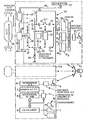
- the radiotelephone network for satellite communications shown schematically in the single figure of the drawing, of the DAMA type, essentially comprises a central station 1, n peripheral stations, 2 1 to 2 n and a telecommunications satellite 3, of the geostationary type.
- the central station 1 essentially comprises, conventionally, an antenna 4, a high frequency transceiver circuit 5, a circuit 6 distributor of intermediate frequencies, a set 7 of modulators / demodulators of intermediate frequencies of the SCPC (Single Channel per Carrier) type , that is to say of the type with a single channel per carrier frequency), a set 8 of track equipment, a computer (or set of duplicated computers) 9, and peripheral members 10 associated with the computer 9, by example of keyboards for entering data controlled by the operator of the central station, display consoles, mass memories, etc.
- SCPC Single Channel per Carrier
- a device 11 for producing synchronization signals and for inserting messages into these synchronization signals is connected, in the central station 1, to the assembly 7 and to the assembly 8, a device 11 for producing synchronization signals and for inserting messages into these synchronization signals, also controlled by the computer 9. It is understood that for reasons of ease of production, the device 11 can be integrated into the assembly 8.
- the telecommunications satellite 3 is a conventional transponder satellite and will therefore not be described in detail.
- peripheral stations 2 1 to 2 n of the network are of similar construction, only the number of their subscribers, therefore the capacity of their automatic exchange, can vary, so only one of these peripheral stations will be described in detail, for example station 21,
- the transmission / reception unit and the antenna may be common to them.
- the peripheral station 2 1 comprises: an antenna 12 followed by a high frequency transceiver circuit 13, and an intermediate frequency distributor 14 which is connected to several, for example three, intermediate frequency modulators / demodulators of the SCPC type referenced 15 1 , 15 2 and 16 3 .
- Each of the modulators / demodulators 15 1 to 15 3 comprises, at the output, an interface, respectively referenced 16, to 16 3 , performing the interfacing with the DAMA (Demand Assignment Multiple Access) circuits connected downstream.
- DAMA Demand Assignment Multiple Access
- the interface 16 1 is connected by two unidirectional two-wire low frequency links 17 and 18 and by a unidirectional control link symbolized by a double arrow 19 to a control and interface circuit 20 of the corresponding SCPC channel (15 i in the present case).
- the reception link 17 connects the low frequency output of the interface 16, to the input of an amplifier 21 with asymmetrical output.
- the output of amplifier 21 is connected by a on the other hand at the reception input of a signaler 22 suitable for the DAMA system, and on the other hand at the input of another amplifier 23 with balanced outputs, preferably with adjustable gain.
- the signaler 22 is connected to a circuit 22a for processing synchronization signals and messages sent by the central station.
- the circuit 22a can be integrated into the signaler 22.
- the outputs of the amplifier 23 are connected to one of the pairs of fixed contacts of a double switch 24 with three positions. To simplify the drawing, all the symmetrical two-wire connections have been represented by a single line and the double switch 24 has been represented as a single switch, and those skilled in the art can easily complete the drawing.
- a second pair of fixed contacts of the controller 24 is connected to ground each time by an impedance 25 whose value is equal to that of the low frequency transmission lines used.
- this impedance is a pure resistance of 600 ohms.
- the third pair of fixed contacts of switch 24 is connected to the output of a telephone signaler 26.
- the pair of movable contacts of switch 24 is connected to the pair of movable contacts of another two-position double switch 27 which also has has been shown in the form of a simple switch and a first pair of fixed contacts of which is connected to the input, 4-wire side, of a 2-wire / 4-wire balancer circuit 28.
- the output, 4-wire side of the balancer circuit 28 is connected to a first pair of fixed contacts of a double switch 29 also shown in the form of a single switch.
- the 2-wire side of the balancer 28 is connected to a telephone line trunk 30.
- the second pairs of fixed contacts of the switches 27 and 29 are respectively connected to an input and to an output of the trunk 30.
- the movable contact of the switch 29 is connected to the input of an amplifier 31 whose asymmetrical output is connected on the one hand to the input of an amplifier 32 with balanced outputs and on the other hand to the input of an amplifier 33 with asymmetrical output and having an automatic gain control.
- the outputs of the amplifier 32 are connected, by a symmetrical 2-wire connection to the telephone signaler 26.
- the output of the amplifier 33 is connected to one of the fixed contacts of a three-position switch 34.
- a second fixed contact of the switch 34 is connected to the output of the flagger 22, and the third fixed contact of the switch 34 is connected to the ground.
- the movable contact of the switch 34 is connected to the input of an amplifier 35 with balanced outputs.
- the symmetrical outputs of the amplifier 35 are connected, by the two-wire link 18 to the interface 16 1 .
- Line trunk 30 and signalman 26 are connected to a PABX 36.
- the station 21 also includes a decentralized intelligence 37 formed by one or more microprocessors. Intelligence 37 is linked by computer management links, symbolized by a large arrow 38, to circuits 20, 26 and 30.
- central station 1 sends a message to configure the signaling channels on a channel called "presentation event synchronization channel" or VSEP
- This V.S.E.P. is preferably taken approximately in the middle of one (or the) of the frequency bands allocated to the network in question, so as to be able to attach to it on one side and the other the signaling channels V.E.P. and V.D.O. described below.
- the central station permanently transmits (or at least during the periods of time during which telephone calls from peripheral stations are likely to occur) a synchronization signal in the form of a rectangular signal whose active edges are for example the rising edges.
- the period of this signal can for example be approximately 250 ms.
- the message for configuring the signaling channels informs the peripheral stations of the instantaneous number of V.E.P. and V.D.O. allocated by the central station to the peripheral stations, according to the density of network traffic.
- this station scans the frequency band of the corresponding transponder of the satellite in search of the V.S.E.P., which is done relatively quickly (generally a few minutes).
- this peripheral station locks onto its frequency to determine the V.D.O. and the V.E.P. of its equipment as described below.
- each SCPC channel of a peripheral station On each SCPC channel of a peripheral station is associated an identity or number of this channel. This identity, wired in the corresponding SCPC circuit (15, to 15 3 in the example of the drawing), is known to the decentralized intelligence (37) of the peripheral station.
- the decentralized intelligence after reception (by the signaler 22) and decoding (by the circuit 22a) of the signaling channel configuration message, determines, by a simple transformation, the identity number of the V.E.P. and V.D.O. associated with each SCPC channel. If for example the central station allocates n V.E.P. 'and m V.D.O. to the network, the number of V.E.P. and V.D.O. associated with a SCPC channel can be the "checksum" of the modulo n and modulo m identity respectively. Thus, each peripheral station knows the number of the V.E.P. and V.D.O. associated with each of its SCPC channels. The V.E.P.
- V.E.P. and V.D.O. are located on either side of the V.S.E.P. At rest, that is to say in the absence of calls from its subscribers, a station listens on its V.D.O.
- the peripheral stations then restart their calls according to the known DAMA procedure until the various calls occur at times separated by at least one active edge of the synchronization signal, and are therefore transmitted by the respective peripheral stations in accordance with different active fronts. Since the period of the synchronization signal is greater than the duration of a call, the central station can then easily take these calls into account and act on them. Thus, there is no risk of partial overlapping of calls originating from different peripheral stations, partial overlapping which would risk being misinterpreted by the central station and giving rise to false connections. On the other hand, cases of entirely overlapping calls are correctly interpreted by the central station, which rejects them outright.
- the central station informs the requesting peripheral station of the VDO associated with the receiving SCPC channel used, to make it wait, and indicates the channel number to it. traffic, namely the VT 1 channel on which these two stations will switch immediately for further communication.
- the central station sends a call to the VDO associated with the receiving SCPC channel corresponding to the subscriber requested from the destination peripheral station, and at the same time the central station indicates to this destination peripheral station the number of the traffic channel. , namely the VT 2 channel different from VT 1 , on which these two stations will switch immediately.
- the channels VT 1 and VT 2 each include two different transmission paths from and to the central station, each occupying a frequency in the allocated frequency band of the satellite transponder.
- the central station communicates individually with the two peripheral stations in question, on two bidirectionally different channels. The link between the central station and the destination peripheral station continues on VT 2 until the called subscriber goes off-hook.
- the central station gives the order to the destination peripheral station, on the same VDO, to switch to VT ,.
- the two peripheral stations are in communication on VT ,, without going through the central station (single-hop link), and the calling subscriber can converse with the requested subscriber.
- said station having detected the hang-up transmits on VT 1 a message to release this traffic channel to the other station, and these two stations release, each in its turn, channel VT 1 .
- the central station can, at any time, send authoritative release messages on VT 1 if this channel is deemed to be blocked.
- the central station can transmit traffic channel change messages on VT 1 during the conversation phase of the peripheral stations.
- the speech channels used at one end of the transponder frequency band (during off-peak hours, for example) on the order of the operator of the central station to allow the transmission of signals.
- broadband, for example video signals on the other channels of this frequency band.
- the different track equipment of the set 8 of track equipment is standardized, that is to say has no function specific item, and are released as and when required under the control of the computer 9.
- the track equipment can be assigned either to VDOs, or VEPs, or to traffic lanes.
- the number of channel equipment associated with the traffic channels is not equal to the total number of network traffic channels, but to the number of calls being established, added to the number of channels in remote monitoring, the latter number may be zero if telemonitoring is only carried out during off-peak hours.
Landscapes
- Engineering & Computer Science (AREA)
- Physics & Mathematics (AREA)
- Astronomy & Astrophysics (AREA)
- Aviation & Aerospace Engineering (AREA)
- General Physics & Mathematics (AREA)
- Computer Networks & Wireless Communication (AREA)
- Signal Processing (AREA)
- Radio Relay Systems (AREA)
Claims (8)
Applications Claiming Priority (2)
| Application Number | Priority Date | Filing Date | Title |
|---|---|---|---|
| FR8017355 | 1980-08-06 | ||
| FR8017355A FR2488469A1 (fr) | 1980-08-06 | 1980-08-06 | Procede d'etablissement de conversations radio-telephoniques dama simple bond par l'intermediaire d'un satellite |
Publications (2)
| Publication Number | Publication Date |
|---|---|
| EP0046420A1 EP0046420A1 (de) | 1982-02-24 |
| EP0046420B1 true EP0046420B1 (de) | 1984-11-14 |
Family
ID=9244947
Family Applications (1)
| Application Number | Title | Priority Date | Filing Date |
|---|---|---|---|
| EP81401205A Expired EP0046420B1 (de) | 1980-08-06 | 1981-07-28 | Verfahren zum Aufbau von DAMA-Funktelefongesprächen mit einmalig durchlaufener Richtfunkstrecke über einen Satelliten |
Country Status (5)
| Country | Link |
|---|---|
| US (1) | US4424417A (de) |
| EP (1) | EP0046420B1 (de) |
| JP (1) | JPS57115038A (de) |
| DE (1) | DE3167194D1 (de) |
| FR (1) | FR2488469A1 (de) |
Families Citing this family (19)
| Publication number | Priority date | Publication date | Assignee | Title |
|---|---|---|---|---|
| JPS6033746A (ja) * | 1983-08-04 | 1985-02-21 | Nec Corp | 衛星回線監視方式 |
| US5303286A (en) * | 1991-03-29 | 1994-04-12 | Space Systems/Loral, Inc. | Wireless telephone/satellite roaming system |
| IT1209566B (it) * | 1984-07-06 | 1989-08-30 | Face Standard Ind | Sistema e procedura per identificare la posizione di un utente radiomobile nell'ambito di una vasta superficie geografica. |
| US5019910A (en) * | 1987-01-29 | 1991-05-28 | Norsat International Inc. | Apparatus for adapting computer for satellite communications |
| IL91529A0 (en) * | 1988-10-28 | 1990-04-29 | Motorola Inc | Satellite cellular telephone and data communication system |
| US5526404A (en) * | 1991-10-10 | 1996-06-11 | Space Systems/Loral, Inc. | Worldwide satellite telephone system and a network coordinating gateway for allocating satellite and terrestrial gateway resources |
| CA2078932C (en) * | 1991-10-10 | 2003-12-02 | Robert A. Wiedeman | Satellite telecommunications system using network coordinating gateways operative with a terrestrial communication system |
| FR2704999B1 (fr) * | 1993-05-04 | 1995-07-21 | Thomson Csf | Reseau de telecommunications d'extremites pour la transmission de donnees par paquets. |
| FR2725573B1 (fr) * | 1994-10-11 | 1996-11-15 | Thomson Csf | Procede et dispositif pour le controle de congestion des echanges sporadiques de paquets de donnees dans un reseau de transmission numerique |
| MY121893A (en) * | 1995-04-28 | 2006-03-31 | Qualcomm Inc | Method and apparatus for providing variable rate data in a communications system using statistical multiplexing. |
| US5812545A (en) * | 1996-01-04 | 1998-09-22 | Orion Atlantic, L.P. | Full mesh satellite-based multimedia networking system |
| US5757784A (en) * | 1996-01-04 | 1998-05-26 | Orion Atlantic, L.P. | Usage-based billing system for full mesh multimedia satellite network |
| US5859840A (en) * | 1996-05-31 | 1999-01-12 | Qualcomm Incorporated | Spread spectrum communication system which defines channel groups comprising selected channels that are additional to a primary channel and transmits group messages during call set up |
| US6496543B1 (en) * | 1996-10-29 | 2002-12-17 | Qualcomm Incorporated | Method and apparatus for providing high speed data communications in a cellular environment |
| US6173007B1 (en) | 1997-01-15 | 2001-01-09 | Qualcomm Inc. | High-data-rate supplemental channel for CDMA telecommunications system |
| US7751370B2 (en) * | 2001-07-13 | 2010-07-06 | Qualcomm Incorporated | Method and apparatus for forward link rate scheduling |
| US6335922B1 (en) | 1997-02-11 | 2002-01-01 | Qualcomm Incorporated | Method and apparatus for forward link rate scheduling |
| US6480521B1 (en) | 1997-03-26 | 2002-11-12 | Qualcomm Incorporated | Method and apparatus for transmitting high speed data in a spread spectrum communications system |
| FR2818058B1 (fr) | 2000-12-13 | 2008-10-24 | Thomson Csf | Procede et systeme pour echanger des informations entre une station principale et un cluster de stations mobiles |
Family Cites Families (3)
| Publication number | Priority date | Publication date | Assignee | Title |
|---|---|---|---|---|
| GB1112589A (en) * | 1965-02-27 | 1968-05-08 | Nippon Electric Co | A wireless communication system utilizing a stationary satellite |
| US3564147A (en) * | 1968-04-05 | 1971-02-16 | Communications Satellite Corp | Local routing channel sharing system and method for communications via a satellite relay |
| US4018993A (en) * | 1974-04-19 | 1977-04-19 | Telefonaktiebolaget L M Ericsson | Telephone system comprising a satellite |
-
1980
- 1980-08-06 FR FR8017355A patent/FR2488469A1/fr active Granted
-
1981
- 1981-07-28 DE DE8181401205T patent/DE3167194D1/de not_active Expired
- 1981-07-28 EP EP81401205A patent/EP0046420B1/de not_active Expired
- 1981-07-31 US US06/289,074 patent/US4424417A/en not_active Expired - Fee Related
- 1981-08-06 JP JP56123559A patent/JPS57115038A/ja active Pending
Non-Patent Citations (1)
| Title |
|---|
| 1976 INTERNATIONAL CONFERENCE ON COMMUNICATIONS, Philadelphia, 14-16 juin 1976 New York, US T. SATOH et al.: "Maritime satellite communications equipment of KDD-experimental system (MARSK-X)" pages 35-7 à 35-12 * |
Also Published As
| Publication number | Publication date |
|---|---|
| EP0046420A1 (de) | 1982-02-24 |
| US4424417A (en) | 1984-01-03 |
| FR2488469B1 (de) | 1982-10-01 |
| DE3167194D1 (en) | 1984-12-20 |
| FR2488469A1 (fr) | 1982-02-12 |
| JPS57115038A (en) | 1982-07-17 |
Similar Documents
| Publication | Publication Date | Title |
|---|---|---|
| EP0046420B1 (de) | Verfahren zum Aufbau von DAMA-Funktelefongesprächen mit einmalig durchlaufener Richtfunkstrecke über einen Satelliten | |
| BE1001871A4 (fr) | Dispositif et procede pour obtenir de la souplesse en matiere de frequence dans des systemes de communication numerique. | |
| EP0095959B1 (de) | Funkverbindungssystem nach dem Frequenzsprungverfahren | |
| EP1238550B1 (de) | Verfahren zur steuerung eines kommunikationskanals, den mehrere stationen gemeinsam nutzen | |
| FR2705181A1 (fr) | Système de télécommunications avec accès aléatoire à plusieurs voies. | |
| EP0204191B1 (de) | Verfahren und Anordnung zur Satellitenübertragung mit TDMA | |
| FR2472897A1 (fr) | Dispositif de transmission d'information de commande dans un systeme de commutation | |
| JPH09501550A (ja) | ローカルisdn無線伝送システム | |
| FR2472896A1 (fr) | Systeme de commutation de telecommunications | |
| US3803405A (en) | Data transmission system | |
| FR2472895A1 (fr) | Dispositif de verification de continuite pour un systeme de commutation telephonique | |
| US6233429B1 (en) | VSAT satellite telecommunications system | |
| EP0200275B1 (de) | Multiplex-Nachrichtenübertragungssystem | |
| JPH0630485B2 (ja) | 時分割双方向伝送方式 | |
| EP0097541B1 (de) | Ortsfeste Station eines Funkverbindungssystems nach dem Frequenzsprungverfahren mit Sendern mit austauschbarer Zuordnung | |
| FR2517146A1 (fr) | Procede utilise pour la gestion du trafic d'informations dans une cellule formee de plusieurs chaines radio et dispositif mettant en oeuvre ce procede | |
| EP1198906B1 (de) | Funkübertragungsverfahren zwischen einer basisstation und mobilen endgeräten, basisstation und mobile endgeräte dafür | |
| JPH06503692A (ja) | Tdma距離設定 | |
| EP0161162B1 (de) | Automatische Vermittlungsanlage mit Video-Schaltmatrix | |
| EP0466590B1 (de) | Digitales Kommunikationssystem für eine digitale dienstintegrierte Fernsprechanlage | |
| EP0530098B1 (de) | Verfahren und Anordnung für Nachrichtenübertragung zwischen Geräten einer Kommunikationsanlage | |
| FR2762957A1 (fr) | Systeme de radiocommunication bidirectionnel et procede d'etablissement de communications | |
| FR2690023A1 (fr) | Station de base pour installation de radio-communication. | |
| JPS58117744A (ja) | 通信方式 | |
| Pouzin | Local area networks |
Legal Events
| Date | Code | Title | Description |
|---|---|---|---|
| PUAI | Public reference made under article 153(3) epc to a published international application that has entered the european phase |
Free format text: ORIGINAL CODE: 0009012 |
|
| AK | Designated contracting states |
Designated state(s): BE DE GB IT |
|
| 17P | Request for examination filed |
Effective date: 19820311 |
|
| ITF | It: translation for a ep patent filed |
Owner name: JACOBACCI & PERANI S.P.A. |
|
| GRAA | (expected) grant |
Free format text: ORIGINAL CODE: 0009210 |
|
| AK | Designated contracting states |
Designated state(s): BE DE GB IT |
|
| REF | Corresponds to: |
Ref document number: 3167194 Country of ref document: DE Date of ref document: 19841220 |
|
| PLBE | No opposition filed within time limit |
Free format text: ORIGINAL CODE: 0009261 |
|
| STAA | Information on the status of an ep patent application or granted ep patent |
Free format text: STATUS: NO OPPOSITION FILED WITHIN TIME LIMIT |
|
| 26N | No opposition filed | ||
| PG25 | Lapsed in a contracting state [announced via postgrant information from national office to epo] |
Ref country code: GB Effective date: 19880728 |
|
| PG25 | Lapsed in a contracting state [announced via postgrant information from national office to epo] |
Ref country code: BE Effective date: 19880731 |
|
| BERE | Be: lapsed |
Owner name: LMT RADIO PROFESSIONNELLE Effective date: 19880731 |
|
| GBPC | Gb: european patent ceased through non-payment of renewal fee | ||
| PG25 | Lapsed in a contracting state [announced via postgrant information from national office to epo] |
Ref country code: DE Effective date: 19890401 |