EP0046366A2 - Stickstoffproduktion durch Lufttrennung - Google Patents
Stickstoffproduktion durch Lufttrennung Download PDFInfo
- Publication number
- EP0046366A2 EP0046366A2 EP81303666A EP81303666A EP0046366A2 EP 0046366 A2 EP0046366 A2 EP 0046366A2 EP 81303666 A EP81303666 A EP 81303666A EP 81303666 A EP81303666 A EP 81303666A EP 0046366 A2 EP0046366 A2 EP 0046366A2
- Authority
- EP
- European Patent Office
- Prior art keywords
- feed air
- oxygen
- passage
- heat exchanger
- stream
- Prior art date
- Legal status (The legal status is an assumption and is not a legal conclusion. Google has not performed a legal analysis and makes no representation as to the accuracy of the status listed.)
- Granted
Links
- IJGRMHOSHXDMSA-UHFFFAOYSA-N Atomic nitrogen Chemical compound N#N IJGRMHOSHXDMSA-UHFFFAOYSA-N 0.000 title claims abstract description 143
- 229910052757 nitrogen Inorganic materials 0.000 title claims abstract description 70
- 238000000926 separation method Methods 0.000 title claims description 9
- 238000004519 manufacturing process Methods 0.000 title abstract description 5
- QVGXLLKOCUKJST-UHFFFAOYSA-N atomic oxygen Chemical compound [O] QVGXLLKOCUKJST-UHFFFAOYSA-N 0.000 claims abstract description 83
- 239000001301 oxygen Substances 0.000 claims abstract description 83
- 229910052760 oxygen Inorganic materials 0.000 claims abstract description 83
- 239000002699 waste material Substances 0.000 claims abstract description 58
- 239000007788 liquid Substances 0.000 claims abstract description 51
- XLYOFNOQVPJJNP-UHFFFAOYSA-N water Substances O XLYOFNOQVPJJNP-UHFFFAOYSA-N 0.000 claims abstract description 29
- 239000000203 mixture Substances 0.000 claims abstract description 20
- 238000005194 fractionation Methods 0.000 claims abstract description 14
- 238000001704 evaporation Methods 0.000 claims abstract description 7
- 238000000859 sublimation Methods 0.000 claims abstract description 7
- 230000008022 sublimation Effects 0.000 claims abstract description 7
- 230000008020 evaporation Effects 0.000 claims abstract description 6
- 238000000034 method Methods 0.000 claims description 20
- 230000001172 regenerating effect Effects 0.000 claims description 12
- 238000004821 distillation Methods 0.000 claims description 7
- 238000007599 discharging Methods 0.000 claims description 6
- 238000002156 mixing Methods 0.000 claims description 5
- 238000011144 upstream manufacturing Methods 0.000 claims description 5
- 238000001816 cooling Methods 0.000 claims 2
- 239000003570 air Substances 0.000 description 94
- 239000000047 product Substances 0.000 description 24
- 229910002092 carbon dioxide Inorganic materials 0.000 description 22
- CURLTUGMZLYLDI-UHFFFAOYSA-N Carbon dioxide Chemical compound O=C=O CURLTUGMZLYLDI-UHFFFAOYSA-N 0.000 description 7
- 239000000499 gel Substances 0.000 description 4
- 239000001569 carbon dioxide Substances 0.000 description 3
- 230000007423 decrease Effects 0.000 description 3
- 229910001873 dinitrogen Inorganic materials 0.000 description 3
- 239000007787 solid Substances 0.000 description 3
- VUZPPFZMUPKLLV-UHFFFAOYSA-N methane;hydrate Chemical compound C.O VUZPPFZMUPKLLV-UHFFFAOYSA-N 0.000 description 2
- 239000002808 molecular sieve Substances 0.000 description 2
- URGAHOPLAPQHLN-UHFFFAOYSA-N sodium aluminosilicate Chemical compound [Na+].[Al+3].[O-][Si]([O-])=O.[O-][Si]([O-])=O URGAHOPLAPQHLN-UHFFFAOYSA-N 0.000 description 2
- 238000012546 transfer Methods 0.000 description 2
- VYPSYNLAJGMNEJ-UHFFFAOYSA-N Silicium dioxide Chemical compound O=[Si]=O VYPSYNLAJGMNEJ-UHFFFAOYSA-N 0.000 description 1
- 230000002745 absorbent Effects 0.000 description 1
- 239000002250 absorbent Substances 0.000 description 1
- 238000013459 approach Methods 0.000 description 1
- 230000000712 assembly Effects 0.000 description 1
- 238000000429 assembly Methods 0.000 description 1
- 239000003610 charcoal Substances 0.000 description 1
- 239000000356 contaminant Substances 0.000 description 1
- 238000011109 contamination Methods 0.000 description 1
- 238000010586 diagram Methods 0.000 description 1
- 238000005265 energy consumption Methods 0.000 description 1
- 239000012530 fluid Substances 0.000 description 1
- 229930195733 hydrocarbon Natural products 0.000 description 1
- 150000002430 hydrocarbons Chemical class 0.000 description 1
- 239000012263 liquid product Substances 0.000 description 1
- 238000012423 maintenance Methods 0.000 description 1
- 238000012986 modification Methods 0.000 description 1
- 230000004048 modification Effects 0.000 description 1
- 238000005057 refrigeration Methods 0.000 description 1
- 239000000741 silica gel Substances 0.000 description 1
- 229910002027 silica gel Inorganic materials 0.000 description 1
Images

Classifications
-
- F—MECHANICAL ENGINEERING; LIGHTING; HEATING; WEAPONS; BLASTING
- F25—REFRIGERATION OR COOLING; COMBINED HEATING AND REFRIGERATION SYSTEMS; HEAT PUMP SYSTEMS; MANUFACTURE OR STORAGE OF ICE; LIQUEFACTION SOLIDIFICATION OF GASES
- F25J—LIQUEFACTION, SOLIDIFICATION OR SEPARATION OF GASES OR GASEOUS OR LIQUEFIED GASEOUS MIXTURES BY PRESSURE AND COLD TREATMENT OR BY BRINGING THEM INTO THE SUPERCRITICAL STATE
- F25J3/00—Processes or apparatus for separating the constituents of gaseous or liquefied gaseous mixtures involving the use of liquefaction or solidification
- F25J3/02—Processes or apparatus for separating the constituents of gaseous or liquefied gaseous mixtures involving the use of liquefaction or solidification by rectification, i.e. by continuous interchange of heat and material between a vapour stream and a liquid stream
- F25J3/04—Processes or apparatus for separating the constituents of gaseous or liquefied gaseous mixtures involving the use of liquefaction or solidification by rectification, i.e. by continuous interchange of heat and material between a vapour stream and a liquid stream for air
- F25J3/04248—Generation of cold for compensating heat leaks or liquid production, e.g. by Joule-Thompson expansion
- F25J3/04284—Generation of cold for compensating heat leaks or liquid production, e.g. by Joule-Thompson expansion using internal refrigeration by open-loop gas work expansion, e.g. of intermediate or oxygen enriched (waste-)streams
- F25J3/0429—Generation of cold for compensating heat leaks or liquid production, e.g. by Joule-Thompson expansion using internal refrigeration by open-loop gas work expansion, e.g. of intermediate or oxygen enriched (waste-)streams of feed air, e.g. used as waste or product air or expanded into an auxiliary column
-
- F—MECHANICAL ENGINEERING; LIGHTING; HEATING; WEAPONS; BLASTING
- F25—REFRIGERATION OR COOLING; COMBINED HEATING AND REFRIGERATION SYSTEMS; HEAT PUMP SYSTEMS; MANUFACTURE OR STORAGE OF ICE; LIQUEFACTION SOLIDIFICATION OF GASES
- F25J—LIQUEFACTION, SOLIDIFICATION OR SEPARATION OF GASES OR GASEOUS OR LIQUEFIED GASEOUS MIXTURES BY PRESSURE AND COLD TREATMENT OR BY BRINGING THEM INTO THE SUPERCRITICAL STATE
- F25J3/00—Processes or apparatus for separating the constituents of gaseous or liquefied gaseous mixtures involving the use of liquefaction or solidification
- F25J3/02—Processes or apparatus for separating the constituents of gaseous or liquefied gaseous mixtures involving the use of liquefaction or solidification by rectification, i.e. by continuous interchange of heat and material between a vapour stream and a liquid stream
- F25J3/04—Processes or apparatus for separating the constituents of gaseous or liquefied gaseous mixtures involving the use of liquefaction or solidification by rectification, i.e. by continuous interchange of heat and material between a vapour stream and a liquid stream for air
- F25J3/04248—Generation of cold for compensating heat leaks or liquid production, e.g. by Joule-Thompson expansion
- F25J3/04375—Details relating to the work expansion, e.g. process parameter etc.
- F25J3/04393—Details relating to the work expansion, e.g. process parameter etc. using multiple or multistage gas work expansion
-
- F—MECHANICAL ENGINEERING; LIGHTING; HEATING; WEAPONS; BLASTING
- F25—REFRIGERATION OR COOLING; COMBINED HEATING AND REFRIGERATION SYSTEMS; HEAT PUMP SYSTEMS; MANUFACTURE OR STORAGE OF ICE; LIQUEFACTION SOLIDIFICATION OF GASES
- F25J—LIQUEFACTION, SOLIDIFICATION OR SEPARATION OF GASES OR GASEOUS OR LIQUEFIED GASEOUS MIXTURES BY PRESSURE AND COLD TREATMENT OR BY BRINGING THEM INTO THE SUPERCRITICAL STATE
- F25J3/00—Processes or apparatus for separating the constituents of gaseous or liquefied gaseous mixtures involving the use of liquefaction or solidification
- F25J3/02—Processes or apparatus for separating the constituents of gaseous or liquefied gaseous mixtures involving the use of liquefaction or solidification by rectification, i.e. by continuous interchange of heat and material between a vapour stream and a liquid stream
- F25J3/04—Processes or apparatus for separating the constituents of gaseous or liquefied gaseous mixtures involving the use of liquefaction or solidification by rectification, i.e. by continuous interchange of heat and material between a vapour stream and a liquid stream for air
- F25J3/04624—Processes or apparatus for separating the constituents of gaseous or liquefied gaseous mixtures involving the use of liquefaction or solidification by rectification, i.e. by continuous interchange of heat and material between a vapour stream and a liquid stream for air using integrated mass and heat exchange, so-called non-adiabatic rectification, e.g. dephlegmator, reflux exchanger
-
- F—MECHANICAL ENGINEERING; LIGHTING; HEATING; WEAPONS; BLASTING
- F25—REFRIGERATION OR COOLING; COMBINED HEATING AND REFRIGERATION SYSTEMS; HEAT PUMP SYSTEMS; MANUFACTURE OR STORAGE OF ICE; LIQUEFACTION SOLIDIFICATION OF GASES
- F25J—LIQUEFACTION, SOLIDIFICATION OR SEPARATION OF GASES OR GASEOUS OR LIQUEFIED GASEOUS MIXTURES BY PRESSURE AND COLD TREATMENT OR BY BRINGING THEM INTO THE SUPERCRITICAL STATE
- F25J2200/00—Processes or apparatus using separation by rectification
- F25J2200/02—Processes or apparatus using separation by rectification in a single pressure main column system
-
- F—MECHANICAL ENGINEERING; LIGHTING; HEATING; WEAPONS; BLASTING
- F25—REFRIGERATION OR COOLING; COMBINED HEATING AND REFRIGERATION SYSTEMS; HEAT PUMP SYSTEMS; MANUFACTURE OR STORAGE OF ICE; LIQUEFACTION SOLIDIFICATION OF GASES
- F25J—LIQUEFACTION, SOLIDIFICATION OR SEPARATION OF GASES OR GASEOUS OR LIQUEFIED GASEOUS MIXTURES BY PRESSURE AND COLD TREATMENT OR BY BRINGING THEM INTO THE SUPERCRITICAL STATE
- F25J2245/00—Processes or apparatus involving steps for recycling of process streams
- F25J2245/40—Processes or apparatus involving steps for recycling of process streams the recycled stream being air
-
- F—MECHANICAL ENGINEERING; LIGHTING; HEATING; WEAPONS; BLASTING
- F25—REFRIGERATION OR COOLING; COMBINED HEATING AND REFRIGERATION SYSTEMS; HEAT PUMP SYSTEMS; MANUFACTURE OR STORAGE OF ICE; LIQUEFACTION SOLIDIFICATION OF GASES
- F25J—LIQUEFACTION, SOLIDIFICATION OR SEPARATION OF GASES OR GASEOUS OR LIQUEFIED GASEOUS MIXTURES BY PRESSURE AND COLD TREATMENT OR BY BRINGING THEM INTO THE SUPERCRITICAL STATE
- F25J2270/00—Refrigeration techniques used
- F25J2270/02—Internal refrigeration with liquid vaporising loop
-
- F—MECHANICAL ENGINEERING; LIGHTING; HEATING; WEAPONS; BLASTING
- F25—REFRIGERATION OR COOLING; COMBINED HEATING AND REFRIGERATION SYSTEMS; HEAT PUMP SYSTEMS; MANUFACTURE OR STORAGE OF ICE; LIQUEFACTION SOLIDIFICATION OF GASES
- F25J—LIQUEFACTION, SOLIDIFICATION OR SEPARATION OF GASES OR GASEOUS OR LIQUEFIED GASEOUS MIXTURES BY PRESSURE AND COLD TREATMENT OR BY BRINGING THEM INTO THE SUPERCRITICAL STATE
- F25J2290/00—Other details not covered by groups F25J2200/00 - F25J2280/00
- F25J2290/10—Mathematical formulae, modeling, plot or curves; Design methods
-
- Y—GENERAL TAGGING OF NEW TECHNOLOGICAL DEVELOPMENTS; GENERAL TAGGING OF CROSS-SECTIONAL TECHNOLOGIES SPANNING OVER SEVERAL SECTIONS OF THE IPC; TECHNICAL SUBJECTS COVERED BY FORMER USPC CROSS-REFERENCE ART COLLECTIONS [XRACs] AND DIGESTS
- Y10—TECHNICAL SUBJECTS COVERED BY FORMER USPC
- Y10S—TECHNICAL SUBJECTS COVERED BY FORMER USPC CROSS-REFERENCE ART COLLECTIONS [XRACs] AND DIGESTS
- Y10S62/00—Refrigeration
- Y10S62/902—Apparatus
- Y10S62/908—Filter or absorber
Definitions
- This invention relates to the separation of nitrogen from air by rectification, and is particularly concerned with improved procedure for the separation of nitrogen from air employing a non-adiabatic air fractioning system, in conjunction with a reversing heat exchanger for removal of water vapour and carbon dioxide, from the feed air.
- the present invention provides a process for the separation of nitrogen from air, which comprises:
- production of nitrogen from air is carried out by compressing air, e.g. to about 3 atmospheres, and passing the compressed feed air to alternate passages of a reversing heat exchanger in heat exchange relation with a oxygen-rich waste stream, whereby water vapour and C0 2 in the feed are frozen on the surface of the heat exchange passage.
- a reversing heat exchanger in heat exchange relation with a oxygen-rich waste stream, whereby water vapour and C0 2 in the feed are frozen on the surface of the heat exchange passage.
- a portion of the feed air is withdrawn at an intermediate point in the reversing exchanger and is expanded in a turbine.
- the air passing through the head exchanger is fed through a non-adiabatic fractionating device for carrying out a differential distillation, whereby by oxygen-rich liquid is condensed and withdrawn, and nitrogen is withdrawn as overhead.
- the oxygen-rich liquid can be mixed with the portion of feed air discharged from the turbine and such mixture as well as the nitrogen overhead product, are passed through the fractionation system in countercurrent heat exchange relation to the feed air being separated in the fractionation zone.
- the waste oxygen stream exiting the heat exchange passage of the fractionating zone is passed through the reversing passages of the reversing heat exchanger, and the fractionation is carried out so that there is only about 3°R temperature difference between the waste oxygen stream and nitrogen product stream, and the feed air at the cold end of the reversing heat exchanger.
- the nitrogen product stream is passed through a separate passage of the reversing heat exchanger.
- the nitrogen gas at the overhead of the fractionator is warmed in the countercurrent heat exchange passage by the partially condensing feed air exiting the bottom of the fractionating device.
- the fractionation process is carried out under conditions such that the oxygen-rich fluid, as well as the nitrogen product, both removed from separate heat exchange passages of the fractionator, are within 3°R of the incoming feed air at the cold end of the regenerative heat exchanger.
- That portion of the feed air which is removed at an intermediate point in the reversing regenerative heat exchanger is tapped from the exchanger at a point upstream or above the cold end of the exchanger, thereby creating a mass imbalance in the cold portion of the exchanger.
- the warmer air so trapped is first passed through an absorbent trap prior to expansion, for removal of the final traces of C0 2 and hydrocarbons.
- the process for the separation of nitrogen from air basically comprises:
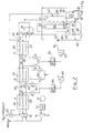
- air is compressed at 10 to about 3 atmospheres cooled to near ambient temperature at 12 and free water is separated in a separator at 14.
- the air feed then enters a reversing regenerative heat exchanger indicated generally at 18, through a reversing valve 16, which is connected to two passages 20 and 22 of the reversing regenerative heat exchanger 18, comprised of three units A, B, and C.
- the heat exchanger contains heat exchange passages 20 for feed air and 22 for the waste oxygen-rich air stream and also a heat exchange passage 24 for nitrogen product.
- Reversing valve 16 together with the check valve assemblies such as 26, described more fully hereinafter, cause the feed air at 3 atmospheres in passage 20 to alternate passages with the oxygen-rich waste stream, which is at one atmosphere in passage 22.
- the feed air in 20 is cooled in concurrent heat exchange with the oxygen-rich waste stream at 22 and the nitrogen product in 24, water vapour and C0 2 are frozen on the surface of the heat exchange passage 20.
- the reversing valve 16 actuates to direct the feed air to the passage 22 previously occupied by the waste stream, and the low pressure waste stream flows through the passage 20 previously occupied by the air stream, sublimating and evaporating the frozen deposits of C0 2 and water vapour.
- the heat exchanger is designed so that a complete reversing cycle occurs every 15 minutes.
- a portion, of the feed air is withdrawn from the exchanger at a tap point 28, with a temperature of about 198°R and is passed via check valve 26 through a gel trap 30 which can contain silica gel, charcoal, or a molecular seive, to remove the last traces of C0 2 , and the air is then expanded in a turbine 32, and discharged at 34 at approximately 1 atmosphere and 153°R.
- the remainder of the air feed is further cooled in passage 20 of unit C of the heat exchanger 18 exiting at 36 at about 176°R.
- the cooled air is then fed via line 38 to the fractionating device indicated at 40, entering the bottom 42 of the fractionating column 43 of such device.
- oxygen-rich liquid is progressively condensed from the vapour moving upward, until pure nitrogen is taken off as overhead at 44.
- the nitrogen product pressure is maintained at 3 atmospheres by the back pressure regulator 45.
- the oxygen-rich liquid withdrawn at 46 from the bottom of the fractionating column is throttled from 3 atmospheres to 1 atmosphere by the liquid level control valve 48, and is mixed at 50 with the turbine exhaust at 34.
- the resulting mixture is introduced at 52 into the top of the fractionatoing device 40 and flows counter-current to the air being separated in the fractionating zone 43, in heat exchange passage 54, and exits the bottom of the fractionating device at 56 and enters the cold end 94 of heat exchanger 18, at a temperature of about 173°R, or only 3°R colder than tyhe feed air temperature exiting unit C of the heat exchanger at 36.
- the product nitrogen at 44 flows through a heat exchang passage 60 downwardly within the fractionation device 40 and exits at 62 and enters the cold end 94 of exchanger 18, also at about 173°R.
- the fractionating device 40 is of the type similar to that shown in my above patent 3,508,412.
- the exiting oxygen-rich air stream at 56 enters passage 22 of heat exchanger 18 at the cold end 94 thereof, and is discharged via valve 16 as waste.
- the nitrogen stream at 62 enters passage 24 at the cold end 94 of the heat exchanger 18 and is discharged via valve 45 as N 2 product.
- a portion of the oxygen-rich liquid at 46 is diverted at 66 via valve 68 and passed through a nitrogen condenser 70 in heat exchange relation with a portion of the nitrogen in line 62, bypassed at 72 to the condenser.
- the cold oxygen-rich vapour discharged from the condenser at 74 is returned to the top of the heat exchange pass 54 of the fractionating system or device 40.
- the liquid nitrogen product at 76 is recovered via valve 78.
- This difficulty can be resolved by addiing a second intermediate tap at 80 in the heat exchanger at a warmer location than the first tap at 28.
- Part of the feed air is withdrawn at about 260°R, and after passing through check valve 82 and gel trap 84, is expanded through turbine 85 to 1 atmosphere at about 198°R.
- the cold expanded air then passes through check valve assembly 86 and enters the waste stream 22 at a point 88 in the exchanger, and at approximately the point 28 where air is withdrawn for passage through the first turbine 32.
- Trumpler passes indicated at 90 and 91, provided in units B and C of the reversing exchanger, can be used instead of the air bleeds at 28 and 80. Feed air is cooled completely to 176°R at the cold end of the heat exchanger, at 92. Then the portion which is to be expanded in the turbine 32 is warmed to 198°R in the Trumpler pass 91 of unit C. The remaining portion of the air which is to be fed to turbine 85 is further warmed to 282°R by passage through the secon Trumpler pass 90 of unit B.
- the Trumpler pass is useful in certain instances, because it eliminates the gel traps at 30 and 84, and some of the check valves, i.e. 26 and 82. This decreases the cost of the equipment and the maintenance, but the disadvantage is that it cannot handle load changes. Accordingly, the Trumpler pass should be used only where a constant load is maintained.
- the present invention involves several novel features.
- One of these features is the manner in which the heat exchange in the reversing heat exchanger 18 and the mass transfer zone in the non-adiabatic differential distillation device 40 are arranged to result in the temperature of both the waste oxygen-rich stream and the nitrogen product stream leaving the distillation device, being at a temperature only a few degrees, that is only 3°R below the air feed temperature at the cold end of the regenerative heat exchanger. This permits facile removal of solid carbon dioxide and water from the feed air passages by the waste stream during reversal of the feed air and waste streams.
- Both the nitrogen product stream and the refrigeration stream which includes the waste oxygen-rich stream pass in countercurrent heat exchange relation with the feed in in the mass transfer fractionation zone 43, to maintain the low temperature difference between the waste and product streams 22 and 24, and the feed air stream 20 at the cold end 94 of the reversing heat exchanger.
- Another novel feature is the manner of locating the feed apoints for the two turboexpanders to maintain a correct temperature profile throughout the entire heat exchanger so as to permit the use of reversing exchangers while producing liquid nitrogen product, nitrogen gas product, or a mixture thereof. If only liquid nitrogen is produced heat exchange passage 24 is not utilized.
- the bleed tap at 28 for turbine 32 imbalances the mass flow so that the temperature at the exit of the exchanger can be pinched to as smalled a termperature difference as required.
- the second turbine 85 is employed when liquid nitrogen is withdrawn.
- the withdrawl of thje liquid nitrogen starts to affect the mass imbalance in the lower temperature portion of the heat exchanger so that the temperature difference in the heat exchanger at the point where mass is withdrawn to feed the first turbine is too great to affect C0 2 removal in the reversing exchanger. Therefore, a second turbine is employed with a warmer inlet temperature to create a mass imbalance in the intermediate section of the reversing exchanger and thereby keeping the temperature difference throughout the entire length of the heat exchanger under acceptable limits for C0 2 removal.
- the invention provides a novel process and system for separating nitrogen from air, employing a differential distillation apparatus in conjuncttion with a reversing regenerative heat exchanger under process conditions such that C0 2 and water frozen in the feed air passages can be readily removed from the heat exchangers.
Landscapes
- Engineering & Computer Science (AREA)
- Physics & Mathematics (AREA)
- Mechanical Engineering (AREA)
- Thermal Sciences (AREA)
- General Engineering & Computer Science (AREA)
- Separation By Low-Temperature Treatments (AREA)
Applications Claiming Priority (2)
| Application Number | Priority Date | Filing Date | Title |
|---|---|---|---|
| US06/178,294 US4289515A (en) | 1980-08-15 | 1980-08-15 | Production of nitrogen by air separation |
| US178294 | 1980-08-15 |
Publications (3)
| Publication Number | Publication Date |
|---|---|
| EP0046366A2 true EP0046366A2 (de) | 1982-02-24 |
| EP0046366A3 EP0046366A3 (en) | 1982-03-10 |
| EP0046366B1 EP0046366B1 (de) | 1985-03-20 |
Family
ID=22651976
Family Applications (1)
| Application Number | Title | Priority Date | Filing Date |
|---|---|---|---|
| EP81303666A Expired EP0046366B1 (de) | 1980-08-15 | 1981-08-12 | Stickstoffproduktion durch Lufttrennung |
Country Status (5)
| Country | Link |
|---|---|
| US (1) | US4289515A (de) |
| EP (1) | EP0046366B1 (de) |
| JP (1) | JPS5914707B2 (de) |
| CA (1) | CA1144057A (de) |
| DE (1) | DE3169386D1 (de) |
Families Citing this family (3)
| Publication number | Priority date | Publication date | Assignee | Title |
|---|---|---|---|---|
| JPS6364513U (de) * | 1986-10-20 | 1988-04-28 | ||
| DE4017410A1 (de) * | 1989-06-02 | 1990-12-06 | Hitachi Ltd | Verfahren und vorrichtung zur herstellung von extrem reinem stickstoff |
| US5921108A (en) * | 1997-12-02 | 1999-07-13 | Praxair Technology, Inc. | Reflux condenser cryogenic rectification system for producing lower purity oxygen |
Family Cites Families (12)
| Publication number | Priority date | Publication date | Assignee | Title |
|---|---|---|---|---|
| US1626345A (en) * | 1922-03-16 | 1927-04-26 | L Air Liquide Soc | Method of separating gaseous mixtures |
| US2460859A (en) * | 1944-05-01 | 1949-02-08 | Kellogg M W Co | Method of gas separation including impurity removing steps |
| NL102363C (de) * | 1953-11-12 | |||
| US3066493A (en) * | 1957-08-12 | 1962-12-04 | Union Carbide Corp | Process and apparatus for purifying and separating compressed gas mixtures |
| US3064441A (en) * | 1958-12-09 | 1962-11-20 | Union Carbide Corp | Low temperature cleaning of an impurity-containing gas |
| GB897812A (en) * | 1960-01-07 | 1962-05-30 | British Oxygen Co Ltd | Cooling and purification of gas mixtures |
| US3264831A (en) * | 1962-01-12 | 1966-08-09 | Linde Ag | Method and apparatus for the separation of gas mixtures |
| DE1196220B (de) * | 1962-10-17 | 1965-07-08 | Basf Ag | Einrichtung zum Verhueten der Verunreinigung von durch Tieftemperaturzerlegung erhaltenen reinen Gasen |
| DE1275076B (de) * | 1965-07-20 | 1968-08-14 | Linde Ag | Verfahren zur Durchfuehrung des Waermeaustausches bei der Tieftemperaturzerlegung von Gasgemischen |
| US3508412A (en) * | 1966-08-12 | 1970-04-28 | Mc Donnell Douglas Corp | Production of nitrogen by air separation |
| US3535887A (en) * | 1967-12-01 | 1970-10-27 | Mc Donnell Douglas Corp | High purity oxygen production from air by plural stage separation of plural streams of compressed air with utilization of recompressed overhead as a source of heat exchange |
| GB1331458A (en) * | 1970-12-22 | 1973-09-26 | Petrocarbon Dev Ltd | Single column liquid nitrogen plant |
-
1980
- 1980-08-15 US US06/178,294 patent/US4289515A/en not_active Expired - Lifetime
-
1981
- 1981-08-10 CA CA000383532A patent/CA1144057A/en not_active Expired
- 1981-08-12 DE DE8181303666T patent/DE3169386D1/de not_active Expired
- 1981-08-12 EP EP81303666A patent/EP0046366B1/de not_active Expired
- 1981-08-13 JP JP56126054A patent/JPS5914707B2/ja not_active Expired
Also Published As
| Publication number | Publication date |
|---|---|
| DE3169386D1 (en) | 1985-04-25 |
| US4289515A (en) | 1981-09-15 |
| JPS5760163A (en) | 1982-04-10 |
| JPS5914707B2 (ja) | 1984-04-05 |
| EP0046366A3 (en) | 1982-03-10 |
| EP0046366B1 (de) | 1985-03-20 |
| CA1144057A (en) | 1983-04-05 |
Similar Documents
| Publication | Publication Date | Title |
|---|---|---|
| CA2448467C (en) | Nitrogen rejection method and apparatus | |
| US4531371A (en) | Process and apparatus for producing nitrogen and oxygen | |
| EP0684438B1 (de) | Lufttrennung | |
| US20060260358A1 (en) | Gas separation liquefaction means and processes | |
| WO1981002291A1 (en) | Method for purifying a gas mixture | |
| US3363427A (en) | Production of ultrahigh purity oxygen with removal of hydrocarbon impurities | |
| KR950031896A (ko) | 순수한 아르곤을 회수하기 위한 방법 및 장치 | |
| JP2004028572A (ja) | 空気精留法及び混合塔とクリプトン・キセノン回収装置とを備えた空気精留設備 | |
| US3373574A (en) | Recovery of c hydrocarbons from gas mixtures containing hydrogen | |
| US4308043A (en) | Production of oxygen by air separation | |
| CA2271667A1 (en) | Method and apparatus for controlling condensation of gaseous hydrocarbon stream | |
| US4783208A (en) | Air separation | |
| US3886756A (en) | Separation of gases | |
| US2982108A (en) | Separation of air | |
| US2918801A (en) | Process and apparatus for separating gas mixtures | |
| US2825212A (en) | Process for separating a compressed gas mixture | |
| US3264831A (en) | Method and apparatus for the separation of gas mixtures | |
| RU2069293C1 (ru) | Криогенный способ получения азота из воздуха | |
| US3039274A (en) | Process and apparatus for purifying and separating compressed gas mixtures | |
| US4289515A (en) | Production of nitrogen by air separation | |
| US2982107A (en) | Separation of the elements of air | |
| US2802349A (en) | Removing impurities from a gas liquefaction system with aid of extraneous gas stream | |
| US4530708A (en) | Air separation method and apparatus therefor | |
| US3488677A (en) | Process for purification of natural gas | |
| US2411711A (en) | Method and apparatus for separating and liquefying gases |
Legal Events
| Date | Code | Title | Description |
|---|---|---|---|
| PUAI | Public reference made under article 153(3) epc to a published international application that has entered the european phase |
Free format text: ORIGINAL CODE: 0009012 |
|
| PUAL | Search report despatched |
Free format text: ORIGINAL CODE: 0009013 |
|
| AK | Designated contracting states |
Designated state(s): DE FR GB IT |
|
| AK | Designated contracting states |
Designated state(s): DE FR GB IT |
|
| 17P | Request for examination filed |
Effective date: 19820804 |
|
| ITF | It: translation for a ep patent filed | ||
| GRAA | (expected) grant |
Free format text: ORIGINAL CODE: 0009210 |
|
| AK | Designated contracting states |
Designated state(s): DE FR GB IT |
|
| REF | Corresponds to: |
Ref document number: 3169386 Country of ref document: DE Date of ref document: 19850425 |
|
| ET | Fr: translation filed | ||
| PLBE | No opposition filed within time limit |
Free format text: ORIGINAL CODE: 0009261 |
|
| STAA | Information on the status of an ep patent application or granted ep patent |
Free format text: STATUS: NO OPPOSITION FILED WITHIN TIME LIMIT |
|
| 26N | No opposition filed | ||
| PG25 | Lapsed in a contracting state [announced via postgrant information from national office to epo] |
Ref country code: GB Free format text: LAPSE BECAUSE OF NON-PAYMENT OF DUE FEES Effective date: 19880812 |
|
| PG25 | Lapsed in a contracting state [announced via postgrant information from national office to epo] |
Ref country code: FR Free format text: LAPSE BECAUSE OF NON-PAYMENT OF DUE FEES Effective date: 19890428 |
|
| PG25 | Lapsed in a contracting state [announced via postgrant information from national office to epo] |
Ref country code: DE Effective date: 19890503 |
|
| GBPC | Gb: european patent ceased through non-payment of renewal fee | ||
| REG | Reference to a national code |
Ref country code: FR Ref legal event code: ST |