EP0046175A1 - Rouleau revêtu d'un élastomère, et procédé et appareil pour sa fabrication - Google Patents
Rouleau revêtu d'un élastomère, et procédé et appareil pour sa fabrication Download PDFInfo
- Publication number
- EP0046175A1 EP0046175A1 EP81104941A EP81104941A EP0046175A1 EP 0046175 A1 EP0046175 A1 EP 0046175A1 EP 81104941 A EP81104941 A EP 81104941A EP 81104941 A EP81104941 A EP 81104941A EP 0046175 A1 EP0046175 A1 EP 0046175A1
- Authority
- EP
- European Patent Office
- Prior art keywords
- disc
- rolls
- segment
- reciprocation
- cylindrical
- Prior art date
- Legal status (The legal status is an assumption and is not a legal conclusion. Google has not performed a legal analysis and makes no representation as to the accuracy of the status listed.)
- Withdrawn
Links
Images

Classifications
-
- B—PERFORMING OPERATIONS; TRANSPORTING
- B05—SPRAYING OR ATOMISING IN GENERAL; APPLYING FLUENT MATERIALS TO SURFACES, IN GENERAL
- B05D—PROCESSES FOR APPLYING FLUENT MATERIALS TO SURFACES, IN GENERAL
- B05D1/00—Processes for applying liquids or other fluent materials
- B05D1/02—Processes for applying liquids or other fluent materials performed by spraying
- B05D1/04—Processes for applying liquids or other fluent materials performed by spraying involving the use of an electrostatic field
-
- B—PERFORMING OPERATIONS; TRANSPORTING
- B05—SPRAYING OR ATOMISING IN GENERAL; APPLYING FLUENT MATERIALS TO SURFACES, IN GENERAL
- B05B—SPRAYING APPARATUS; ATOMISING APPARATUS; NOZZLES
- B05B5/00—Electrostatic spraying apparatus; Spraying apparatus with means for charging the spray electrically; Apparatus for spraying liquids or other fluent materials by other electric means
- B05B5/08—Plant for applying liquids or other fluent materials to objects
- B05B5/082—Plant for applying liquids or other fluent materials to objects characterised by means for supporting, holding or conveying the objects
Definitions
- the invention relates to elastomeric coating of cylindrical rolls.
- Elastomeric coatings have been applied to rollers for many years, using a variety of techniques. Typical of these techniques are:.
- rollers where a thick coating is either not required or is detrimental.
- Such applications include:
- Pressure atomization in the spray coating of elastomeric systems has been successfully used for very thin coatings, in the range 0.001 to 0.003 inch, but it has been found lacking as a coating technique for coats in the thickness range of 0.005 to 0.012 inch, for reasons of poor thickness uniformity.
- the technique also exhibits the same detriment as in paint application, namely, excessive material wastage. This wastage is particularly serious when using expensive elastomers, such as polyurethanes, polysiloxanes, and fluoroelastomers.
- a specific object is to provide such a technique which can produce uniform coating thickness in the thickness range up to about 0.030 inch.
- Another specific object is to provide such a technique which lends itself to high-volume productivity, with high coating efficiency and consequent low material wastage.
- a further object is to provide such a technique which is adaptable to both liquid and solid elastomers, and which is reproducible as to product quality.
- a general object is to meet the above objects with a technique and apparatus which is applicable to a variety of roller-core constructions and dimensions, and with lower tooling cost than normally required.
- the invention achieves the foregoing objects and other features, in the specific context of elastomeric coating of cylindrical rolls, by conveying a succession of like vertically-oriented cylindrical rolls along an endless path of movement which includes a segment that is cylindrically arcuate about a vertical axis of electrostatic spray-disc rotation.
- a solvent mixture of elastomeric-ingredient material is continuously applied to the rotating disc while the latter is vertically oscillated over the length of the rolls and while the rolls in the segment are continuously rotated about their individual axes.
- the path of movement includes a course which leaves the segment and later rejoins the segment, after passage through a zone of partial curing, where a major fraction of the solvent is evaporated, prior to recycled entry into the segment for receiving the next increment of coat application.
- a conveyor 10 comprises an endless loop of articulated links, continuously driven by motor means 11.
- Small circles 12 at equal spacing along the conveyor 10 will be understood to designate like cylindrical rollers, sometimes referred to as roller cores 12.
- these rollers are coated by a centrifugally discharged, electrostatically charged spray or mist of a solvent mixture of elastomeric material, such spray or mist issuing from a continuously rotating disc 13, driven by motor means 14, within an arcuate spray-booth region having an outer wall 15.
- conveyor 10 guides the suspended rollers 12 along an arcuate path which lies in a horizontal plane and which extends a major fraction of a full circle about the rotary axis of disc 13, placing the suspended rollers at substantial radial offset from disc 13.
- each roller suspension system provides for driven rotation of the roller about its individual suspension axis (namely, the roller axis); this is accomplished by a friction wheel between the suspended roller and the suspension system, the friction wheel engaging an arcuate rub bar 16 while traversing the spray-booth segment of the conveyor path.
- a radiating cylindrical volume characterizes the spray or mist discharge from disc 13; this is achieved by means of a cyclical vertical reciprocation of disc 13 in the course of its continuous rotation, the reciprocating period being very much longer than the rotational period.
- a motor 17 will be understood to provide such reciprocation, and control means 18 serves to regulate both motors 14-17 to assure a desired relationship between reciprocation speed and rotary speed, as may be found best suited for a particular job purpose.
- a zone B is provided for inspection (and also for coated-product removal, and for uncoated roller-core loading).
- the conveyed rollers 12 After passing zone B, the conveyed rollers 12 enter an elongate enclosure, labelled "Flash-Off Tunnel" and comprising zone legs C 1' C 2' C 3 .
- the last of these legs is open to a drying oven, whence the conveyor provides a relatively short exposure zone E, for motor-drive provision and for guided recycling entry into the spray zone A.
- the enclosed zones C and D provide such conveyor length as to assure desired extraction of volatiles and substantial curing of the incremental elastomeric coating which results from passage of each roller through the spray zone A.
- the conveyor cycle repeats for as many such cured incremental deposits as are specified for a particular job. And the process may be run con- tinously, with full assurance of precisely the same exposure to a plurality of successive full loads of the conveyor 10.
- a clearly identifiable brightly painted lug between two adjacent roll-suspension systems on the conveyor 10 may mark a starting point, such as the point labeled X in the loading zone B; and, as the conveyor moves through zone B, the apparatus is loaded with uncoated metal roller cores 12 for all roll-suspension systems following the X-marked location, until the X-marked location re-emerges from zone A.
- zone B passes through zone B (and preferably, just as it enters zone B), a cycle count is registered, as may be noted automatically by a counter-trip device, schematically suggested at T.
- a counter-trip device schematically suggested at T.
- each emerging fully coated roller is removed and replaced by a new uncoated roller core, in succession, until all the fully coated rollers have been replaced, the counting means T being reset to enable the same number of incremental coats to be applied to the fresh load of uncoated roller cores.
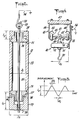
- Fig. 2 the suspension system for one of the many rollers 12 to be coated appears only to the extent of its suspension hook 20; the roller core 12 will have been preassembled with support elements (to be described), including a central suspension rod 21 having a ring link 22 at its upper end, for easily removable engagement to the suspension hook 20.
- the roller 12 is for use as a toner-fusing roll in electrostatic printing equipment.
- the roller core . 12 comprises an elongate metal cylinder 23 of diameter D 1 , having a central bore 24, with a counterbore 25 at each end.
- a mounting hub or end bell 26 is rabbeted to fit each counterbore and to provide a shoulder of diameter to match that of cylinder 23.
- the bore of each hub 26 is sized for the ultimate mounting-shaft requirements of the end-use machine.
- the elastomeric coating is to be applied, within close tolerances as to uniformity and thickness, to the external cylindrical surface of the roller assembly 23-26.
- roller 12 for coating includes assembly to rod 21, via cylindrical lower and upper masking caps 27-28 of diameter D 2 ⁇ D 1 , and retained via a removable pin 29.
- the lower cap 27 is of length L,, greater than the length L 2 of upper cap 28.
- Caps 27-28 are bored and counterbored for non-interference with adjacent hub (26) and rod (21) parts, and at abutment with the outward flange portion of each hub 26, the outer circumferential corner of each of caps 27-28 has a significant chamfer 27' which may be at 45° but is preferably at substantially 60° to the radial plane of mask- to-hub abutment, thereby establishing a clearly recognizable discontinuity at the longitudinal limits of the cylindrical surface (diameter D 1 ).
- the radial depth ⁇ R 1 should substantially exceed any radial clearance in the fit of a cap 27 (28) to its adjacent hub 26, in order to assure such recognizable discontinuity.
- Fig. 3 is a simplified view taken on a diameter of the cylindrically arcuate path of roller conveyance around the rotary axis of the spray disc 13, and it will be understood that in Fig. 3 the radial offset R 2 between disc 13 and the path of rollers 12 has been deliberately compressed, in order to provide a better illustration of co-operating elements.
- the mean diameter D 3 of the path of roller movement through the spray segment A may be such as to provide a radial offset R 2 which is approximately the diameter D 4 of the disc 13, but which in any event is large enough to assure against arcing to ground.
- the disc 13 is shown at the upper limit of its reciprocation cycle, wherein the flat upper surface of disc 13 is at an upper plane of centrifugal discharge, which plane has axially lapped the upper caps 28 of exposed roller-support structures to the extent ⁇ L 2 , being ⁇ L 2 .
- the lower reciprocated position of the upper surface of disc 13 is shown at phantom outline 13', where said upper surface has similarly lapped the lower caps 27 to the extent ⁇ L 1 , being ⁇ L 1 ' the full reciprocating stroke L R imparted by motor 17 and its associated disc-reciprocating mechanism (suggested at 17' in Fig.
- FIG. 5 graphically displays the preferred reciprocation cycle, wherein all axially displaced motion of disc 13 is at substantially uniform speed, therebeing a short dwell of selectively controllable duration between reversing halves of the stroke cycle.
- Fig. 3 schematically suggests a suitable supply means 30 for solvent mixture of elastomeric material, to be deposited on disc 13 for the described centrifugal discharge.
- a nozzle-ended tube 31 will be understood to be elongate and flexible and to be carried with the described vertical- reciprocation motion, described for disc 13.
- the flexible length of tube 31 will further be understood to be of such extent as not to impair the reciprocation cycle or the fixed orientation of the nozzle end of tube 31 (with respect to rotating disc 13).
- the supply means may thus be a fixedly mounted tank, equipped with a metering displacement pump 32 for control of the flow of the solvent mixture in tube 31 to its nozzle end.
- such charging means comprises a grounded polarizing- voltage source 33, which may be physically outside the spray zone A, and an elongate flexible insulated conductor 34 to brush means 35 having continuous electrical contact with the reciprocated rotating disc 13, it being understood that all reciprocating and rotary drive connections to disc 13 are suitably insulated with respect to the grounding of means 33.
- the other pole of the electrostatic field is established by grounding the conveyed rollers 12; in Fig. 1, such grounding is schematically suggested at 34, via contact with moving conductive elements of the conveyor 10, at or in the vicinity of zone A.
- the polarizing sense should be such that a particle- attracting electrostatic field is established to each of the rollers 12 in zone A; therefore, the output polarity of means 33 to brush 35 is negative.
- Fig. 4 is a simplified showing of a typical roller-suspension unit 40, constituting one of the endless succession of such elements (each equipped with its hook 20) in the described endless conveyor system 10.
- a central body 41 is secured at mid-span of an axle 42, the ends of which are equipped with crowned antifriction track rollers 43-43'.
- Rollers 43-43' have guided rolling contact with opposed C-shaped rail channels 44-44' of the track component of conveyor system 10, the transverse center 45 of symmetry of which will be understood to follow the continuous and endless course described in connection with Fig. 1; the suspended and fixed relation of rail channels 44-44' may be achieved via bracket structure 46 secured to the underside of a suitable base 47 at spaced locations along the endless course.
- aligned equal-projection arms 48 perpendicular to axle 42 and extending forwardly and rearwardly of axle 42 may be but one unit of an endless chain-like succession of like articulated units, interconnected at the outer ends of arms 48.
- the second element 51 includes a motion pick-off roll 52 of such diameter D 5 as to slightly interfere with locally fixed positioning of the rub bar or strip 16, and of course the suspension hook 20 is also part of the rotatable element 51.
- roll 52 develops its slight interference with the rub bar 16
- the friction of the engagement is such as, by reaction, to drive hook 20 (and a roller suspended therefrom) in continuous rotation, by reason of conveyor movement through the zone A extent of bar 16.
- disc 13 While disc 13 is continuously rotating and is vertically reciprocated, a mist of negatively charged droplets of solvent mixture is being centrifugally and electrostatically induced to deposit upon the continuously rotating cylindrical surface 23 of each roller 12 as it is conveyed through zone A.
- the product 12 was a toner-fusing roll for use in a xerographic copying machine, wherein the described roller cores 12 had a measured diameter D 1 of approximately 3 inches and length L 3 of approximately 15 inches. They were equipped with a 1ower masking cap 27 having a length L 1 of 4 inches, and an upper masking cap 28 having a length L 2 of 2.5 inches, being then hung as described from the conveyor system 10.
- the disc diameter D 4 was 10 inches, and the cylindrically arcuate segmental path of conveyor 10 in zone A was of 36-inch diameter (D 3 ). Conveyor speed was set at 5.6 feet per minute.
- the disc-reciprocation stroke and disc position were set for a lower mask overlap ⁇ L 1 of 3 inches (i.e.
- the rate of reciprocation (Fig. 5) was set at 14 cycles per minute, the lower hesitation or dwell ⁇ t 1 being set at 0.5 second and the upper hesitation or dwell ⁇ t 2 being set at 0.75 second.
- Disc 13 rotation was set at 1950 rpm, and delivery of solution at 31 was set at 510 cc/min.
- the size of the motion pick-off rollers 52 was such as to effect approximately twelve revolutions of each workpiece (12) about its own central axis, in the course of its 270° zone-A traverse, , in engagement with the rub bar 16.
- the solution contained and dispensed from source 30 comprised:
- the solution was made using appropriate mixing techniques and tested for viscosity and concentration, being then charged to the dispensing tank 30 and kept under agitation as long as required.
- solution-metering pumps were started and will be understood to be sufficiently symbolized by the means 32 of Fig. 1; at the same time, the conveyor drive (11), disc rotation (14), and disc reciprocation (17) were started; and a polarizing voltage of 40-kV was applied to the brushes 35 with respect to ground.
- the parts 12 were conveyed continuously through zone A for a total of 9 (10) cycles, to produce a total coating thickness of 7.5 (8.0) mils, flash-off and curing being accomplished as appropriate, with each conveyed cycle.
- the resulting product was again a toner-fusing roll, but characterized by a silicone surface produced by the described technique, to substantially the same developed coating thickness as for Example I.
- the process described has the ability to set and control each of these parameters and consequently allow fabrication of elastomeric-coated rollers and other type parts efficiently and at uniform thicknesses up to 0.030 inch and at high-volume productivity levels. This is believed to be an accomplishment unique to the field of elastomeric coating.
- the speed of rotation of disc 13 will generally be in the range between 500 and 4000 rpm, the particular speed applicable for a given case being a function of droplet-particle size, and a sufficient restraint on drying droplets in flight.
- 1950 rp m was found to be a top speed of disc rotation, to avoid a drying of solution on the disc.
- droplet size and the dry-out problem are also a function of the particular solvent used, as well as the concentration of elastomeric material in solution (generally in the range between 5 and 75%), suitable solvents being taken from the group which includes:
- the voltage of electrotatic charging will be in the range between 10 and 120 kV, and the specific voltage selected for a given coating job will be a function of the conductivity of the solvent mixture.
- the voltage gradient in the charged region is in the range 4500 to 4800 volts per inch, in that it is our observation that the negatively charged droplets in the spray are attracted into roller-surface contact over a substantial arcuate extent, approaching + 45° with respect to the instantaneous plane which includes the disc axis and the axis of any given suspended roller 12.
- zone A of electrostatic deposition be at all times under negative pressure with respect to surrounding ambient conditions.
- an exhaust is continuously operative as a downdraft, suggested by arrows 55 in Fig. 3 and involving air drawn into zone A from above the upper rim of the booth wall 15.
- a plenum chamber (not shown) is located below the coating region to collect the exhaust flow, which often includes volatile components which are heavier than air. From the plenum chamber, an exhaust fan associated with a vertical stack 56 assures safe venting, and it will be understood that the system includes such filters, scrubbers and other devices as may be necessary to assure stack discharge of an environmentally safe exhaust.
Landscapes
- Nozzles (AREA)
- Electrostatic Spraying Apparatus (AREA)
- Application Of Or Painting With Fluid Materials (AREA)
Applications Claiming Priority (2)
| Application Number | Priority Date | Filing Date | Title |
|---|---|---|---|
| US17953580A | 1980-08-19 | 1980-08-19 | |
| US179535 | 2002-06-25 |
Publications (1)
| Publication Number | Publication Date |
|---|---|
| EP0046175A1 true EP0046175A1 (fr) | 1982-02-24 |
Family
ID=22656996
Family Applications (1)
| Application Number | Title | Priority Date | Filing Date |
|---|---|---|---|
| EP81104941A Withdrawn EP0046175A1 (fr) | 1980-08-19 | 1981-06-25 | Rouleau revêtu d'un élastomère, et procédé et appareil pour sa fabrication |
Country Status (2)
| Country | Link |
|---|---|
| EP (1) | EP0046175A1 (fr) |
| JP (1) | JPS5759657A (fr) |
Cited By (7)
| Publication number | Priority date | Publication date | Assignee | Title |
|---|---|---|---|---|
| EP0435577A2 (fr) * | 1989-12-27 | 1991-07-03 | Xerox Corporation | Méthode et appareil pour revêtir des substrats de récepteurs dans un arrangement planétaire fermÀ© |
| ES2071576A2 (es) * | 1993-08-04 | 1995-06-16 | Navalon Saez Concepcion | Metodo para pintar en continuo cadenas metalicas de eslabones y la correspondiente instalacion |
| GB2259657B (en) * | 1991-09-05 | 1996-03-06 | Intech Exports | Electrostatic powder coating |
| US6020528A (en) * | 1996-03-04 | 2000-02-01 | Ciba Specialty Chemicals Corporation | Alkylphenylbisacylphosphine oxides and photoinitiator mixtures |
| WO2002092240A1 (fr) * | 2001-03-27 | 2002-11-21 | Krones Ag | Procede et dispositif pour munir un recipient en matiere plastique d'un revetement |
| WO2003057373A1 (fr) * | 2002-01-09 | 2003-07-17 | Krones Ag | Dispositif et procede pour appliquer un revetement sur des recipients |
| WO2007103361A2 (fr) * | 2006-03-07 | 2007-09-13 | Boston Scientific Scimed, Inc. | Systeme et procede de revetement par pulverisation de dispositifs medicaux multiples a l'aide d'un atomiseur rotatif |
Citations (3)
| Publication number | Priority date | Publication date | Assignee | Title |
|---|---|---|---|---|
| US2780565A (en) * | 1953-07-17 | 1957-02-05 | Ransburg Electro Coating Corp | Electrostatic spray coating system and method |
| US2884341A (en) * | 1955-03-07 | 1959-04-28 | Ransburg Electro Coating Corp | Electrostatic spray coating method |
| US3128201A (en) * | 1955-05-06 | 1964-04-07 | Ransburg Electro Coating Corp | Electrostatic spray coating method and apparatus |
-
1981
- 1981-06-25 EP EP81104941A patent/EP0046175A1/fr not_active Withdrawn
- 1981-08-17 JP JP12787981A patent/JPS5759657A/ja active Pending
Patent Citations (3)
| Publication number | Priority date | Publication date | Assignee | Title |
|---|---|---|---|---|
| US2780565A (en) * | 1953-07-17 | 1957-02-05 | Ransburg Electro Coating Corp | Electrostatic spray coating system and method |
| US2884341A (en) * | 1955-03-07 | 1959-04-28 | Ransburg Electro Coating Corp | Electrostatic spray coating method |
| US3128201A (en) * | 1955-05-06 | 1964-04-07 | Ransburg Electro Coating Corp | Electrostatic spray coating method and apparatus |
Cited By (13)
| Publication number | Priority date | Publication date | Assignee | Title |
|---|---|---|---|---|
| EP0435577A2 (fr) * | 1989-12-27 | 1991-07-03 | Xerox Corporation | Méthode et appareil pour revêtir des substrats de récepteurs dans un arrangement planétaire fermÀ© |
| EP0435568A2 (fr) * | 1989-12-27 | 1991-07-03 | Xerox Corporation | Méthode et appareil pour nettoyer, revêtir et durcir des substrats de récepteurs dans un arrangement planétaire fermé |
| EP0435577A3 (en) * | 1989-12-27 | 1992-02-05 | Xerox Corporation | Method and apparatus for coating receptor substrates in an enclosed planetary array |
| EP0435568A3 (en) * | 1989-12-27 | 1992-02-26 | Xerox Corporation | Method and apparatus for cleaning, coating and curing receptor substrates in an enclosed planetary array |
| US5248529A (en) * | 1989-12-27 | 1993-09-28 | Xerox Corporation | Method of cleaning, coating and curing receptor substrates in an enclosed planetary array |
| GB2259657B (en) * | 1991-09-05 | 1996-03-06 | Intech Exports | Electrostatic powder coating |
| ES2071576A2 (es) * | 1993-08-04 | 1995-06-16 | Navalon Saez Concepcion | Metodo para pintar en continuo cadenas metalicas de eslabones y la correspondiente instalacion |
| US6020528A (en) * | 1996-03-04 | 2000-02-01 | Ciba Specialty Chemicals Corporation | Alkylphenylbisacylphosphine oxides and photoinitiator mixtures |
| WO2002092240A1 (fr) * | 2001-03-27 | 2002-11-21 | Krones Ag | Procede et dispositif pour munir un recipient en matiere plastique d'un revetement |
| WO2003057373A1 (fr) * | 2002-01-09 | 2003-07-17 | Krones Ag | Dispositif et procede pour appliquer un revetement sur des recipients |
| WO2007103361A2 (fr) * | 2006-03-07 | 2007-09-13 | Boston Scientific Scimed, Inc. | Systeme et procede de revetement par pulverisation de dispositifs medicaux multiples a l'aide d'un atomiseur rotatif |
| WO2007103361A3 (fr) * | 2006-03-07 | 2007-10-25 | Boston Scient Scimed Inc | Systeme et procede de revetement par pulverisation de dispositifs medicaux multiples a l'aide d'un atomiseur rotatif |
| US7691431B2 (en) | 2006-03-07 | 2010-04-06 | Boston Scientific Scimed, Inc. | System and method for spray coating multiple medical devices using a rotary atomizer |
Also Published As
| Publication number | Publication date |
|---|---|
| JPS5759657A (en) | 1982-04-10 |
Similar Documents
| Publication | Publication Date | Title |
|---|---|---|
| EP0827429B1 (fr) | Procede et dispositif pour recouvrir des elements de fixation filetes | |
| EP0382503B1 (fr) | Méthode et appareil pour revêtir la surface intérieure d'articles cylindriques creux | |
| US3598626A (en) | Electrostatic method for coating with powder and withdrawing undeposited powder for reuse | |
| US4929319A (en) | Process and device for surface pre-treatment of plastic by means of an electrical corona discharge | |
| JP4237260B2 (ja) | 薄壁エラストマー製品を製造するための方法および装置 | |
| US4144553A (en) | Apparatus for electrodynamic spraying | |
| US2781280A (en) | Method and apparatus for spray coating of articles | |
| US2893894A (en) | Method and apparatus for electrostatically coating | |
| US5711489A (en) | Electrostatic powder coating method and apparatus | |
| US3281076A (en) | Method and apparatus for atomizing liquids | |
| US3411931A (en) | Electrostatic method of applying flock to a paint roller sleeve | |
| EP0046175A1 (fr) | Rouleau revêtu d'un élastomère, et procédé et appareil pour sa fabrication | |
| US3384050A (en) | Electrostatic coating system | |
| MX149160A (es) | Mejoras a metodo y aparato para el recubrimiento electrostatico de objetos con un fluido,por ejemplo tinta liquida | |
| US2993468A (en) | Apparatus for coating with atomized liquid | |
| MXPA00003744A (es) | Metodo y aparato para aplicar un recubrimiento de resina a un sujetador. | |
| US6827780B2 (en) | Method and apparatus for powder coating hollow objects | |
| JPH0938529A (ja) | 静電粉体塗装装置 | |
| US20050287306A1 (en) | Process for electrostatic powder coating an article using triboelectrically charged powder with air jet assist | |
| US4433003A (en) | Electrogasdynamic coating system | |
| US3186864A (en) | Method for electrostatic painting | |
| US5114736A (en) | Method for varying nozzle traversal speed to obtain uniform thickness electrostatically spray coated layers | |
| US4810521A (en) | Elecrostatic coating of rubber-to-metal adhesives on metal parts | |
| CA2223463C (fr) | Procede et dispositif pour recouvrir des elements de fixation filetes | |
| US4898747A (en) | Electrostatic coating of rubber-to-metal adhesives on metal parts |
Legal Events
| Date | Code | Title | Description |
|---|---|---|---|
| PUAI | Public reference made under article 153(3) epc to a published international application that has entered the european phase |
Free format text: ORIGINAL CODE: 0009012 |
|
| AK | Designated contracting states |
Designated state(s): DE FR GB NL SE |
|
| STAA | Information on the status of an ep patent application or granted ep patent |
Free format text: STATUS: THE APPLICATION IS DEEMED TO BE WITHDRAWN |
|
| 18D | Application deemed to be withdrawn |
Effective date: 19830122 |
|
| RIN1 | Information on inventor provided before grant (corrected) |
Inventor name: LORENZONI, FRANK P. Inventor name: RYDER, LYLE C. |