EP0045801B1 - Digital pseudo continuous tone detector - Google Patents
Digital pseudo continuous tone detector Download PDFInfo
- Publication number
- EP0045801B1 EP0045801B1 EP81900771A EP81900771A EP0045801B1 EP 0045801 B1 EP0045801 B1 EP 0045801B1 EP 81900771 A EP81900771 A EP 81900771A EP 81900771 A EP81900771 A EP 81900771A EP 0045801 B1 EP0045801 B1 EP 0045801B1
- Authority
- EP
- European Patent Office
- Prior art keywords
- threshold
- correlation
- tone
- block
- sum
- Prior art date
- Legal status (The legal status is an assumption and is not a legal conclusion. Google has not performed a legal analysis and makes no representation as to the accuracy of the status listed.)
- Expired
Links
- 230000002441 reversible effect Effects 0.000 claims abstract description 56
- 238000001514 detection method Methods 0.000 claims abstract description 33
- 238000000034 method Methods 0.000 claims abstract description 18
- 230000000670 limiting effect Effects 0.000 claims abstract description 8
- 238000012545 processing Methods 0.000 claims description 12
- 230000002829 reductive effect Effects 0.000 claims description 3
- 235000003625 Acrocomia mexicana Nutrition 0.000 claims 1
- 244000202285 Acrocomia mexicana Species 0.000 claims 1
- 238000006243 chemical reaction Methods 0.000 claims 1
- 238000001914 filtration Methods 0.000 claims 1
- 230000002401 inhibitory effect Effects 0.000 claims 1
- 239000011159 matrix material Substances 0.000 abstract description 91
- 238000005070 sampling Methods 0.000 abstract description 9
- 239000000523 sample Substances 0.000 description 71
- 238000010586 diagram Methods 0.000 description 13
- 235000014676 Phragmites communis Nutrition 0.000 description 11
- 238000004590 computer program Methods 0.000 description 7
- 238000004364 calculation method Methods 0.000 description 5
- 244000273256 Phragmites communis Species 0.000 description 4
- 230000006870 function Effects 0.000 description 4
- 238000013459 approach Methods 0.000 description 3
- 238000004891 communication Methods 0.000 description 3
- 238000012360 testing method Methods 0.000 description 3
- 230000005540 biological transmission Effects 0.000 description 2
- 230000010363 phase shift Effects 0.000 description 2
- 238000005096 rolling process Methods 0.000 description 2
- JEYCTXHKTXCGPB-UHFFFAOYSA-N Methaqualone Chemical compound CC1=CC=CC=C1N1C(=O)C2=CC=CC=C2N=C1C JEYCTXHKTXCGPB-UHFFFAOYSA-N 0.000 description 1
- 238000009825 accumulation Methods 0.000 description 1
- 239000013078 crystal Substances 0.000 description 1
- 230000003111 delayed effect Effects 0.000 description 1
- 238000013461 design Methods 0.000 description 1
- 230000000694 effects Effects 0.000 description 1
- 230000036039 immunity Effects 0.000 description 1
- 230000005055 memory storage Effects 0.000 description 1
- 238000012986 modification Methods 0.000 description 1
- 230000004048 modification Effects 0.000 description 1
- 230000002093 peripheral effect Effects 0.000 description 1
- 238000002360 preparation method Methods 0.000 description 1
- 230000000630 rising effect Effects 0.000 description 1
- 230000035945 sensitivity Effects 0.000 description 1
Images



Classifications
-
- H—ELECTRICITY
- H04—ELECTRIC COMMUNICATION TECHNIQUE
- H04W—WIRELESS COMMUNICATION NETWORKS
- H04W88/00—Devices specially adapted for wireless communication networks, e.g. terminals, base stations or access point devices
- H04W88/02—Terminal devices
- H04W88/022—Selective call receivers
- H04W88/025—Selective call decoders
- H04W88/027—Selective call decoders using frequency address codes
-
- H—ELECTRICITY
- H03—ELECTRONIC CIRCUITRY
- H03D—DEMODULATION OR TRANSFERENCE OF MODULATION FROM ONE CARRIER TO ANOTHER
- H03D3/00—Demodulation of angle-, frequency- or phase- modulated oscillations
-
- H—ELECTRICITY
- H03—ELECTRONIC CIRCUITRY
- H03G—CONTROL OF AMPLIFICATION
- H03G3/00—Gain control in amplifiers or frequency changers
- H03G3/005—Control by a pilot signal
Definitions
- This invention relates generally to the electronic signal processing art and, in particular, to an improved digital tone detection method suitable for tone control squelch systems.
- such systems operate by equipping each radio transmitter in the particular radio system with a tone encoder operating on one of the 33 standard EIA channels between 67.0 and 250.3HZ.
- the operator's voice modulates the transmitter in the 300-3000HZ range and simultaneously with the voice, the subaudible tone modulates the transmitter as well.
- Receivers within the radio system are equipped with a frequency selective device (tone decoder) tuned to the same tone frequency as the tone encoder within the transmitters of the system.
- tone decoder normally holds the receiver in the squelched mode. If a received signal is not modulated with the tone or is modulated with a tone that is not on the decoder frequency, then the receiver will remain squelched and the operator will not hear the interference. If a transmission is received having a tone corresponding to the frequency of the tone decoder, the receiver will be unsquelched and the operator will receive the message.
- subaudible tone such as, control of radio repeaters, identifying a particular vehicle out of a plurality of vehicles, alarm and control signal applications, switching radio receiver or transmitter frequencies, switching communication circuits, etc.
- an electronic tone detector which can meet EIA standards and which is easily programmable.
- a method of processing an input signal to detect at least one desired tone of a plurality of tones in accordance with the prior art portion of claim 1 is known from European Patent No. 0008160. This document falls within Article 54(3) of the European Patent Convention.
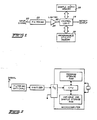
- Fig. 1 is a generalized block diagram illustrating the fundamental blocks of the preferred embodiment of the invention intended for use as a detector for a continuous tone controlled squelch system.
- a signal is applied to an input terminal 20 and coupled to a filter 22.
- the filter 22 is optional, but its use will improve the performance of the system for most applications. When used, it is preferably a low pass or band pass filter.
- the signal from the filter 22 is applied to a limiter 24 which hard limits the signal thus converting the signal into essentially a rectangular waveform.
- the rectangular waveform from the limiter 24 is applied to the input 25 of the control logic 26.
- the control logic 26 samples the applied signal at a fixed rate f s and processes the samples to determine whether a tone of a predetermined desired frequency f o is present.
- processing parameters used by the control logic 26 are stored in a programmable utility memory 30 coupled to the control logic 26.
- the control logic 26 stores sample data in the sample matrix memory 28.
- the processing of the data to permit a tone present/absent decision initially requires that the incoming limiter signal applied to the control logic input 25 be sampled at a fixed rate f s .
- the rate of the sampling must be high enough to permit adequate sampling of the highest frequency tone to be detected.
- the highest frequency tone to be detected is approximately 250HZ and the sampling rate is approximately 1,OOOHZ.
- the control logic 26 samples the rectangular signal, a high value is determined to be +1 and a low value is determined to be a -1 (other values can be used as +1 and 0).
- the input signal is digitized by the combined function of hard limiting and sampling. This digitizing could also be accomplished by means of an A/D converter.
- the digitized sample values are then assigned to a phase subregion (in the preferred embodiment there are four phase subregions and therefore they are phase quadrants) of a local reference waveform which preferably has the same frequency f o as that of the tone to be detected.
- a phase accumulator which is incremented before each sample by a phase increment equal to fJfs stored in the programmable utility memory 30.
- the phase accumulator is then used to address one of four memory locations M l , M 2 , M 3 and M 4 , corresponding to the four phase quadrants.
- Each sample value (either +1 or -1) is then added to the contents of the memory location addressed for that sample.
- phase increment would be .125.
- phase accumulator is started at zero, the first two sample values would be added to memory location M,, the next two to memory location M 2 , the next two to memory location M 3 , etc.
- the control logic 26 adds 39 samples to the four quadrant memory locations M 1 through M 4 during each time subwindow obtaining phase quadrant subtotals for each time subwindow. After 39 samples have been accumulated, the control logic 26 performs correlations against two orthogonal local reference waves using the last nine subwindow phase quadrant subtotals. The data from the last nine subwindows is stored in the sample matrix memory 28. A sine correlation (CS) value is determined according to the expression and a cosine correlation value (CC) according to the expression New correlation values are determined after each subwindow using the phase quadrant subtotals for the most recent nine time subwindows.
- CS sine correlation
- CC cosine correlation value
- the resulting values are then added to obtain a correlation total and compared at the end of each subwindow to a threshold value of 91 to make a tone detection decision. Once a tone has been detected, the detect threshold is lowered to 48, thus providing detect threshold hysteresis.
- Standard continuous tone control squelch systems require that once a tone has been detected, a state of no detect must be reached more quickly than if the tone had simply been removed, in order to avoid an annoying squelch tail. This is accomplished by using a "reverse burst" by suddenly phase shifting the tone signal by 180 degrees. Because of the characteristics of the mechanical vibrating reeds commonly used, a 240 degree shift is actually utilized to shutdown the detector in conventional systems, which corresponds to a shift in the reed resonant frequency. In a correlation detection system, the sudden shift causes the detector to see a rising signal when it otherwise would have seen a falling one and vice versa. As a result, whatever digital quantity the detector has built up, will begin to fall.
- the correlation totals can be limited by limiting the number of samples used once a tone detection has occurred. This limits the amount that the correlation totals must fall in order to drop below the threshold.
- floating submatrix limiting is provided to obtain reverse burst turn off times adequate to meet required standards for continuous tone controlled squelch systems.
- the control logic 26 compares the correlation total to a reverse burst limit threshold. This threshold is set sufficiently above the initial detect threshold to assure that a strong correlation has been built up before starting to limit, in order to prevent limiting from driving the correlations below the initial detection level.
- the reverse burst limit threshold is exceeded, sample matrix is limited to a lesser number of subwindows (seven in the preferred embodiment), thus a smaller number of subwindows are used to obtain the correlation total.
- the correlation total drops below a limit drop out threshold, the total number of subwindows used is increased to normal. The number of subwindows removed depends upon the subwindow size relative to the entire matrix and the amount of limiting required to achieve the desired turn off time.
- the control logic 26 shifts to a reverse burst mode.
- the next subwindow is defined to be a new bottom forthe sample matrix, then following two subwindows are eliminated from the sample matrix and the correlation values for these two subwindows following the new bottom are subtracted from the correlation total. These two subwindows are not used again until the correlation total falls below a limit drop out threshold of 67. Because the eliminated subwindows can occur anywhere in the matrix, the limited submatrix is said to be floating.
- the detect frequency of the novel detector is shifted 1.2HZ when the detector is in the reverse burst mode so that the approximately 240 degree phase shift of the reverse burst tone relative to the desired tone frequency f o will be 180 degrees relative to the shifted tone.
- the amount of the frequency shift required is determined by the design bandwidth of the system.
- background detection is provided to anticipate and correct this reverse burst false detect problem.
- a second background detector is centered on the frequency of the desired tone but with bandwidth characteristics such that it detects adjacent tone channels as well.
- This detector can be of any of the available types including mechanical reed detectors, but is preferably a correlation detector.
- the background detector will find not only the center frequency tone, but also nearby tones. If the main detector determines that the correlation total is above the detect threshold, background detector is checked to determine if it has sensed a tone for longer than the time period required for a detection by the main detector. If the background detector has such a detection, then it is assumed that an adjacent tone has been present and that there was a reverse burst on the adjacent tone which caused a false detect. No detect is allowed as a result and the system is reinitialized. Since the wide bandwidth of the background detector allows quick detection, if the background detect has been for less than the time needed for the main detector to detect a tone, then the detect is allowed.
- the background detector be a correlation detector using the same samples and reference phase quadrant memory locations M i , M 2 , M 3 , M 4 as the main detector, except that the tone detect decisions are based on fewer subwindows.
- the background detector is a correlation detector based upon the samples of three time subwindows. At the end of the three subwindows, the background detector memory is cleared, the detection decision is stored, and the background detector continues correlating using samples over the next three time subwindows.
- the main detector correlation total exceeds the initial detect threshold of 91, a check is made to be sure less than 7 detections by the background detector have been stored before a tone detect is allowed.
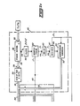
- Fig. 2 shows a detailed block diagram of a digital pseudo continuous correlation tone detector according to the invention.
- a signal normally from the discriminator of a receiver, is applied at an input terminal 22 of a filter 20 which is preferably a low pass filter.
- the filtered output of the filter 20 is coupled directly to an input terminal 24 of a limiter 25 where the filtered signal is limited to transform it into essentially a rectangular waveform with only a high or a low level, at an output terminal 26.
- the limiter output terminal 26 is coupled to the up/down (U/D) input of each up/down counter in a matrix of up/down counters indicated generally at 30.
- These counters of the matrix 30 are arranged in four columns, as shown, labelled M ll M 2 , M 3 , M 4 .
- Each column is comprised of a plurality of counters equal to the number of time subwindows used by the system (although nine are used in the preferred embodiment, only three are shown).
- Each counter is incremented by 1 if the level on its U/D input is high and decremented by one if the level on its U/D input is low, if at the same time, its unique address is present on its ADR input and a sample pulse occurs on the S input. All counters in the counter matrix 30 which are not addressed remain unchanged.
- Control circuitry 40 includes a phase accumulator 32 which comprises a multibit binary adder and register (not shown in detail) which are used to generate an address signal on an output bus 33.
- a sample clock signal with frequency equal to the sampling frequency f. is generated by an oscillator 36 and applied to the C input 34 of the phase accumulator.
- An input terminal 35 is provided which is coupled to a programmable utility memory location 37 in which a phase increment value equal to fJfs is stored where f o is the frequency of the desired tone to be detected. This value fJfs is the phase change that occurs in the local reference waveform in the interval between sampling clock pulses.
- the fraction fdfs is added to the accumulator at each sampling pulse from the clock 36, using modulo 2 addition. On overflow of the adder, the ones are dropped leaving only the fractional part.
- the value in the accumulator is a binary fraction between 0 and 1 with the two most significant bits corresponding to one of four phase quadrants of a local reference waveform with frequency f o . Therefore, upon each sample clock pulse the phase accumulator will be incremented by the phase increment fJfs, and the two most significant bits can be used as address bits for the up/down counters of matrix 30.
- the phase accumulator value is coupled from the output terminal 33 to the input terminal 39 of a circuit 38 which drops all but the two most significant bits. The two most significant bits are coupled to the address bus 54 via the phase address bus 41.
- the signal from the sample clock 36 is also applied to a sample pulser 42 which generates a sampling pulse on the sample control line 43 during each cycle of the sample clock signal.
- the sample pulse signal on the sample control line 43 is coupled to the sample input (S input) of each of the counters in the counter matrix 30. When the pulse occurs, the addressed counter in the counter matrix 30 will sample the signal on its U/D input and will be incremented or decremented accordingly.
- the sample pulse signal is also coupled to the input terminal 44 of a delay circuit 45 as shown.
- the delay circuit 45 generates a delayed pulse on its output terminal 46 which is coupled to a divider 47. The delay is necessary to allow for the settling time of the circuits in the system.
- the divider 47 frequency divides the signal from the delay circuit 45 by the number of samples per subwindow and generates a subwindow pulse on the output terminal 48 at the end of each time subwindow.
- the output terminal 48 is coupled to a subwindow address counter 49.
- the subwindow address counter increments an address which is applied to its output terminal 52 and coupled to the address bus 54 via a subwindow address bus 53.
- the subwindow address contains the most significant bits of the up/down counter address and is combined with the two bits from the phase address bus 41.
- the full address on the address bus 54 is composed of the subwindow address bits which determine which row of the matrix is addressed (each row representing a different subwindow), and the two phase address bits which determine which of the four up/down counters (i.e. which column M l -M 4 ) will be addressed in the subwindow row. All address bits are coupled to the ADR input of each up/down counter.
- each up/down counter will be addressed sequentially so as to sample the input signal and add the sample to the correct phase quadrant memory location M l , M 2 , M 3 , M 4 , when the sample pulse occurs.
- the two bits from the phase accumulator 32 would first address the counter 55 assuming the phase accumulator begins at zero.
- the counter 55 would be incremented or decremented depending upon whether the signal on the U/D input was high or low.
- phase accumulator 32 would be incremented by fJfs. Depending on the value of fJfs, eventually the phase accumulator would be incremented enough to cause the two most significant bits to address the next counter 56. Up until that occurs, upon each sample pulse on the sample control line 43, the first counter 55 would be incremented or decremented. When the second counter 56 is addressed, then counter 56 will sample the signal upon each sample pulse on the S input from the sample control line 43. In this way, each counter accumulates the input samples for its quadrant of the local reference waveform.
- the total sum in each counter is applied to a SUM output terminal (for example, see the SUM output terminal 57 of the up/down counter 55).
- the totals for each counter in each column are applied to summing circuits 70, 72, 74, 76 via a set of SUM busses.
- the totals from column M are coupled to the summing circuit 70 via the SUM busses 61, 62, 63 and 64 where bus 63 represents the SUM bus for all those counters not shown.
- summing circuit 70 produces a total sample sum M i
- summing circuit 72 produces a total sample sum M 2
- summing circuit 74 produces a total sample sum M 3
- summing circuit 76 produces a total sample sum M 4 .
- the sample totals are coupled to the adding circuit 78 such that the M, and M 2 sample totals are added and the M 3 and M 4 totals are subtracted.
- the sample totals are coupled to the adding circuit 80 such that the M, sample total and the M 4 sample total are added and the M 2 and M 3 sample totals are subtracted.
- the resulting value from the adding circuit 78 is applied to the input 82 of the absolute value circuit 83 which takes the absolute value of the quantity applied to its input 82.
- the resulting quantity is the sine correlation value given by
- the resulting quantity from the adder circuit 80 is applied to the input 84 of the absolute value circuit 85 which takes the absolute value of the quantity applied to its input 84.
- the resulting output is the cosine correlation value given by
- These two correlation values are then applied to the summing circuit 86 at its inputs 87 and 88.
- the summing circuit 86 adds the two correlation values obtaining a correlation total which is applied to the input 89 of the comparator 90.
- Another input 91 to the comparator 90 is coupled directly to the subwindow divider 47 so that a subwindow pulse is applied to the enable input 91.
- the correlation total applied to the input 89 is compared to a threshold value.
- a decision is made by comparing the correlation total to the threshold. If the correlation total exceeds the threshold, a decision output signal is generated on the decision output 93.
- the decision output terminal 93 is also coupled to the input terminal 94 of threshold circuit 95. As a result, when a decision output occurs on output terminal 93, a high level is applied to the input terminal 94 of the thresold circuit 95 which changes to a new lower threshold.
- the new lower threshold is then applied to the threshold input 96 of the comparator 90. This results in the comparator 90 comparing the correlation total on its input 89 to a new lower threshold applied to its input 96 after the initial detect occurs. If upon a comparison being made, the decision output 93 goes low because the correlation total applied at input 89 does not exceed the threshold applied at input 96, then the threshold circuit will revert back to the original higher threshold.
- the change output 92 is coupled to the reset inputs of all the counters in the counter matrix 30. As a result, all of the counters of the subwindow row which is addressed at the time the reset pulse occurs are cleared. Thus, once a decision determination has been made, the counters for the next subwindow to take samples will be cleared to prepare them to accumulate a new set of samples.
- Fig. 3 illustrates the preferred embodiment of the invention wherein the control logic and memory are realized via a standard microcomputer.
- the microcomputer shown in Fig. 10 is preferably the commercially available MOSTEK 3870 microcomputer chip.
- the signal to be processed is applied to the input terminal 100 of an optional filter 102.
- the filtered signal from the filter 102 is coupled to the input terminal 104 of the limiter 106.
- the limited output signal from the limiter 106 is coupled to the I/0 input 108 of a microcomputer 110.
- a clock crystal 112 is coupled to the clock inputs 114 and 116.
- the microcomputer 110 will sample the limited signal applied to its input 108, process the sampled information and when the presence of the desired tone is detected, generate a detect indication on a detect output 118.
- MOSTEK 3870 includes the necessary ROM and RAM required for the program.
- a microprocessor with peripheral devices to accomplish the same functions could also be utilized.
- Fig. 4 is a general program flow diagram for the microcomputer of Fig. 3 to implement the present invention as shown in Fig. 3.
- An INITIALIZE routine 120 sets the initial values and triggers the initial operation of the program sequence. From the INITIALIZE routine 120, program flow proceeds to a WAIT routine 129.
- the WAIT routine 129 provides the necessary delay between operations so that samples are taken at the proper intervals. During this waiting period, the microcomputer can be used to perform other functions. After the necessary delay has occurred during the WAIT routine 129, program flow proceeds to the sample block 122.
- the microcomputer samples the input signal applied to the input 108 and program flow proceeds to the next program routine 124.
- the routine 124 identifies the proper memory storage location for the sample according to the phase of a local reference waveform of frequency f o .
- the sample is then stored in the appropriate memory location indicated as M 1 through M 4 .
- program flow passes to decision block 126 which checks to determine if the 39 samples for a subwindow have been taken. If.there have not been enough samples for a subwindow, program flow proceeds to the REVERSE BURST check routine 128. At this point a check is made to determine whether the reverse burst limiter submatrix is required. If so, the routine establishes the floating submatrix and returns program control to the WAIT routine 129. In the WAIT routine 129 enough delay is established so that the next sample is taken at block 122 after the necessary delay. If, .however, the 39 samples needed to form a subwindow had been taken, then program control proceeds to the BACKGROUND DETECTOR routine 132.
- This routine performs the necessary correlation calculations on three subwindows of samples and stores the result.
- Program control then proceeds to block 136 where correlation values are determined and stored in correlation matrices CS and CC and where a correlation total SUMCOR is determined. Following these calculations, the program control proceeds to decision block 138 where the correlation total SUMCOR is compared to the threshold GOOD. If the correlation total SUMCOR is greater than or equal to the threshold GOOD, then program control proceeds to the REVERSE BURST routine 142. In the REVERSE BURST routine 142 it is determined whether the reverse burst floating submatrix is required and, if so, appropriate values are set to establish the floating submatrix.
- Program will then proceed to decision block 144 where the decision flag RCOPFG is checked to determine whether a detect had occurred previously. If a previous detect had been allowed, then program control proceeds to the WAIT routine 129 where the necessary delay is established before taking the next sample. If a detect had not previously been allowed, then program control proceeds to decision block 146 where the background detector variable HLONG is checked to determine if the detect was the result of an adjacent channel reverse burst or a real detect. If the detect was a false detect, then the variable HLONG will be greater than or equal to 7 and the program control will be passed to the INITIALIZE routine where the program will be reinitialized. If the variable HLONG is less than 7, then an allowed detect can occur and program control will proceed to block 148.
- the background detector variable HLONG is checked to determine if the detect was the result of an adjacent channel reverse burst or a real detect. If the detect was a false detect, then the variable HLONG will be greater than or equal to 7 and the program control will be passed to the INI
- the threshold GOOD will be set to a new lower threshold, and the detect flag RCOPFG will be set and output. Program control will then be passed back to the WAIT routine 129 where the necessary delay will be established before the next sample is taken. If, at the decision block 138, it is found that the correlation sum is less than the threshold GOOD, then program control will pass to block 150.
- the subroutine MOVPTR is called. This subroutine determines the location of the subwindow where the next samples will be stored. Program control will then pass to decision block 140 where the detect flag RCOPFG is checked to determine if an allowed detect had occurred. If the detect flag had been set indicating an allowed detected had occurred, then the detect flag RCOPFG is cleared to zero at block 141 and is output.
- Program control then proceeds to the INITIALIZE routine where the entire program is reinitialized. If the detect flag RCOPFG had not been set indicating that no detect had occurred previously, then program control proceeds to the WAIT routine 129 where the appropriate delay is established before the next sample is taken.
- program control proceeds to block 124 which is shown in greater detail in Fig. 5.
- routine 124 is entered at block 124a. At this point the phase increment equal to fJfs is added to a phase accumulator.
- phase accumulator is decoded as indicated at block 124b by using the two most significant bits of the accumulator as a pointer to identify one of the four phase quadrant memory locations, M i , M 2 , M 3 , M 4 0
- the sample is added to the memory location identified to give a subwindow subtotal for each phase quadrant.
- sample counter SMPCTR is decremented as indicated in block 124d. The sample counter is initially set to 39 in INITIALIZE routine 120 shown in Fig. 4.
- the BACKGROUND DETECTOR routine 132 of Fig. 4 is shown in greater detail in Fig. 6. This routine is entered at block 132a in which the background correlation values are calculated.
- BCOR1 is a correlation value made up of the M, subwindow subtotal minus the M 2 subwindow subtotal for up to three consecutive subwindows.
- BCOR2 correlation value is the M 2 subwindow subtotal minus the M 4 subwindow subtotal for up to three consecutive subwindows.
- the background counter BKGCTR is decremented as shown in block 132b.
- the background counter variable BKGCTR is originally set to three in the INITIALIZE routine shown at 120 in Fig. 4. Once the background counter has been decremented, program flow proceeds to decision block 132c where the background counter is checked to determined if it is zero. If the background counter BKGCTR is equal to zero, this indicates that three subwindows have been used to make the background correlation value and therefore a correlation test can be made.
- the program flow will jump to connection point 132k as shown and will proceed to the next routine indicated as block 136 in Fig. 4. If the background counter is equal to zero indicating a correlation test can be made, the background counter is reset to three as shown in block 132d and program flow proceeds to the decision block 132e. At this point the absolute value of BCOR1 and the absolute value of BCOR2 are tested sequentially to see if either is greater than or equal to the background threshold.
- decision block 132i the variable HLONG is checked to determined if it is equal to zero, if not, it is decremented as shown in block 132j. If it is already zero, then program flow proceeds to block 132h as shown in Fig. 6. If the absolute value of BCOR1 or the absolute value of BCOR2 is greater than or equal to the threshold, this indicates that a tone has been detected on either the center channel or the adjacent channels and program flow proceeds to decision block 132f. At this point the variable HLONG is checked to determine if it is equal to or greater than 10.
- program flow proceeds to connection point 132k and from there to the next routine indicated as block 136 of Fig. 4. If the variable HLONG is less than 10, then the variable HLONG is incremented as shown in block 132g and program flow proceeds to block 132h. The value of HLONG is thereby constrained between zero and ten to prevent the value in the microcomputer memory location from rolling over or rolling under. At this point the correlation values BCOR1 and BCOR2 are cleared to prepare the background routine for the next set of three subwindow correlations. Program flow then proceeds to connection point 132K and from there to the next routine indicated at 136 in Fig. 4.
- the net result of the background routine is that at every three subwindows, a correlation is performed and, if a detection occurs, a variable HLONG is incremented to store the effective detection and whenever a detection does not occur at the end of three subwindows, the variable HLONG is decremented to indicate a lack of detection.
- the value of HLONG represents a probability that an undesired tone has been detected.
- CORRELATION TOTAL routine is entered at block 136a at which the subwindow correlation values NEWCS and NEWCC are calculated.
- NEWCS is the value of the sine correlation for the latest subwindow, which is equal to and the variable NEWCC is the cosine correlation for the latest subwindow and is equal to
- program flow proceeds to block 136b where the memory locations M I , M 2 , M 3 and M 4 are cleared in preparation for the next subwindow sample accumulation.
- Program flow then proceeds to block 136c where a value TEMPCS and TEMPCC are calculated.
- TEMPCS is equal to the latest subwindow correlation value NEWCS minus the oldest existing value in the sine correlation matrix CS.
- the exact location in the matrix is determined by the matrix pointer MTXPTR whose value is set initially in the INITIALIZE routine.
- the value of the variable TEMPCC is equal to the latest subwindow cosine correlation value NEWCC minus the oldest existing correlation value in the cosine correlation matrix CC indicated by the value of the matrix pointer MTXPTR.
- program flow proceeds to 136d as shown where total sine and total cosine correlation values are determined. The total sine correlation.
- TOTCS is determined by adding the previously calculated value TEMPCS to the existing total sine correlation value TOTCS.
- the total cosine correlation value TOTCC is given by the total correlation value existing TOTCC plus the value of TEMPCC calculated above.
- the total correlation values TOTCS and TOTCC respectively are equal to the sum of all the correlation values in each correlation matrix CS and CC.
- the total correlation values TOTCS and TOTCC are the total correlation sums against the two orthogonal references for all of the subwindows used to form the full observation window.
- the total number of subwindows is equal to 9.
- Program flow then proceeds to block 136f where the value SUMCOR is calculated by adding the absolute value of the total sine correlation value TOTCS to the absolute value of the total cosine correlation value TOTCC.
- Program flow then proceeds out of the CORRELATION routine indicated at 136 in Fig. . 4 to the decision block 138 shown in Fig. 4.
- the correlation sum SUMCOR is compared to the threshold value GOOD which is initially set in the INITIALIZE routine 120.
- the preferred value for the initial threshold value is 91.
- program flow proceeds to block 150 which calls the MOVPTR subroutine.
- the MOVPTR subroutine is shown in greater detail in Fig. 8. As shown in Fig. 8, the MOVPTR subroutine is entered at block 150a and program flow proceeds to decision block 150b where the reverse burst flag RBFLAG is checked to determine if it is equal to zero. If the reverse burst flag is equal to zero, this means that the REVERSE BURST mode has not been entered and the correlation matrix should not be limited. As a result, program flow proceeds from block 150b to block 150d as shown.
- a temporary variable TEMPA is set equal to one to cause an advance of only one subwindow and program flow proceeds to block 150f.
- the matrix pointer MTXPTR is checked to determine if it is equal to a value RBOT.
- the value RBOT is the real bottom of the correlation matrix and is a constant. If the matrix pointer is equal to the real bottom, then the matrix pointer value is set to a value RTOP.
- RTOP is the real top of the correlation matrix and is a constant. After setting the matrix pointer equal to RTOP, program flow proceeds to block 150i where the value TEMPA is decremented.
- program flow proceeds to block 150i where the variable TEMPA is decremented.
- the variable TEMPA was set to one, therefore, decrementing it the first time will cause the value to go to zero.
- decision block 150j it is determined whether TEMPA is equal to zero, the value of TEMPA will be zero and program flow will proceed to the return block 150k resulting in the program flow returning to the original position in the program.
- the temporary variable TEMPA is set equal to three as shown at block 150e in order to move the matrix pointer MTXPTR over the two unused subwindows. If the matrix pointer MTXPTR is not equal to NBOT, then the temporary variable TEMPA is set equal to one as shown at block 150d. Program flow in each case then proceeds to decision block 150f where it is determined whether the matrix pointer MTXPTR is equal to the real bottom. If the matrix pointer is equal to the real bottom RBOT, then the matrix pointer will be set equal to the real top RTOP as shown in block 150g. Program flow then proceeds to block 150i where the temporary variable TEMPA is decremented.
- the matrix pointer MTXPTR is incremented as shown in block 150h and program flow then proceeds again to block 150i where TEMPA is decremented. After TEMPA is decremented, program flow proceeds to the decision block 150j where it is determined whether TEMPA is equal to zero. If the matrix pointer MTXPTR had not been equal to the new bottom NBOT, then TEMPA will be zero after the first decrementing of TEMPA and program flow will proceed to the return block 150k and the subroutine will then return to the main program at the point at which it was called.
- program flow proceeds from block 150 to decision block 140 as shown in Fig. 4.
- the detect flag RCOPFG is checked to determine whether an allowed detection had previously occurred. It should be recalled that to be at this point in the program it must have been already determined at block 138 that the correlation sum was below the detect threshold. The detect flag must therefore be reset to zero if a detect had previously occurred setting it to one. Therefore, if the detect flag is equal to one, program flow proceeds to block 141 where the detect flag RCOPFG is set to zero and is output to the output port. Program flow then proceeds to the INITIALIZE routine 120 where the program is reinitialized. If, however, the detect flag was not set to one, then program flow proceeds from block 140 to the WAIT routine 129 where the necessary delay is established between samples before the sample is taken at block 122.
- the correlation sum SUMCOR is compared to the reverse burst limit threshold RBTHRESH 1. If the correlation sum is greater than or equal to the reverse burst limit threshold, the program will then be shifted into the reverse burst mode and program flow will therefore proceed to block 142c. At this point the phase increment PHINC is increased by a value corresponding to a frequency shift of 1.2HZ. Therefore, the phase increment is increased by 1.2HZ divided by the sample frequency f s . Program flow then proceeds to block 142d where the MOVPTR subroutine is called and the matrix pointer MTXPTR is changed as described previously.
- the subroutine After the matrix pointer has been changed, the subroutine returns control to block 142e where the variable RBFIX is set equal to one, and the variable NBOT is set equal to MTXPTR. At this point then, the new bottom of the matrix is established as being equal to the existing position of the matrix pointer MTXPTR and the variable RBFIX is set for use to be described later. Making the new bottom of the matrix equal to the subwindow after RBTHRESH1 has been exceeeded, allows the two subwindows following the new bottom, which are to be cleared by the REVERSE BURST CHECK routine 128, to be immediately reused if such clearing drops the value of SUMCOR below the drop-out threshold RBTHRESH2. Program flow then proceeds to connection point 142k from which the program will then proceed to block 144 of Fig. 4.
- program control proceeds to decision block 144.
- the detect flag RCOPFG is checked to determine if it is equal to one. If the detect flag is equal to one, an allowed detect has occurred previously and program flow proceeds to the WAIT routine 129 as shown in Fig. 4 where the necessary delay between samples is established. If, however, the RCOPFG variable is not equal to one, this means that an allowed detect did not set the flag previously and program flow proceeds to decision block 146 shown in Fig. 4. At decision block 146 the variable HLONG is checked to determine if it is greater than or equal to seven.
- variable HLONG is greater than or equal to seven, then the detect is assumed to be a false detect resulting from a reverse burst tone on an adjacent tone channel. As a result, program flow will proceed to the INITIALIZE routine 120 as shown in Fig. 4.
- the threshold variable GOOD is set equal to a hysteresis threshold THRESH2, which in the preferred embodiment is equal to 48.
- the detect flag RCOPFG is set equal to one indicating a detect and this detection flag is output on the output port.
- Program flow then proceeds to the WAIT routine 129 where the necessary delay is established before the next sample is taken at block 122.
- RBFIX is equal to one, this indicates that reverse burst processing of the data is required. Therefore, program flow proceeds to block 128b as shown in Fig. 10.
- a temporary variable TEMPA is set equal to two, a temporary variable TEMPB is set to zero and a temporary variable TEMPC is set to zero.
- the variable RBFIX is cleared to zero. This is required since the processing of the REVERSE BURST CHECK routine is done only after the first sample of the new bottom subwindow just after the new bottom has been defined in block 142.
- RBFIX must be set to equal zero so that it is not entered again until the variable RBFIX is reset to one by the REVERSE BURST routine 142.
- Program flow then proceeds from block 128b to decision block 128c.
- the matrix pointer MTXPTR is checked to determine whether it is equal to RBOT, that is, to see whether the matrix pointer is pointing at the real bottom of the matrix. If the matrix pointer is at the real bottom of the matrix, then the matrix pointer MTXPTR is set equal to the top of the matrix TOPMTX as shown in block 128d.
- the variable TEMPC is set equal to the existing value of TEMPC plus the cosine correlation value from the cosine correlation matrix CC at the subwindow of the present matrix pointer value.
- Program then proceeds to block 128g where the sine correlation and cosine correlation matrix values for the present subwindow are set equal to zero and program flow then proceeds to block 128h where the value of TEMPA is decremented.
- Program flow then proceeds to decision block 128i where it is determined whether the variable TEMPA is equal to zero. Since it was initially set to two, after the first time through the routine, the result of this decision will be NO and program flow will proceed back to block 128c where the previously described process will be repeated.
- the value TEMPA will equal zero and program flow will proceed to block 128j where the total sine correlation value TOTCS will be set equal to the previously existing total sine correlation value TOTCS minus the value of TEMPB. Also the total cosine correlation value TOTCC will be set equal to the previously existing value TOTCC minus the value of TEMPC. The net result is that the correlation matrix is limited and the subwindows which are to be skipped are set to zero and removed from the total correlation values TOTCS and TOTCC. Program flow then proceeds out of the REVERSE BURST CHECK routine and to the WAIT routine 129 as shown in Fig. 4
Landscapes
- Engineering & Computer Science (AREA)
- Computer Networks & Wireless Communication (AREA)
- Signal Processing (AREA)
- Power Engineering (AREA)
- Noise Elimination (AREA)
- Complex Calculations (AREA)
Abstract
Description
- This invention relates generally to the electronic signal processing art and, in particular, to an improved digital tone detection method suitable for tone control squelch systems.
- As a result of the extensive use of radio communications channels presently available, it has become common, especially in heavily populated metropolitan areas, to have several communication systems simultaneously operating on a common radio channel. Operators whose radios are not equipped with some form of tone squelch must listen to all conversations on the channel from transmitters that are within range. This is both annoying and fatiguing for the operators. The use of tone squelch to alleviate the annoyance is a common solution to the problem. A standard for subaudible continuous tone control squelch systems (CTCSS) is covered in an Electronic Industries Association (EIA) Standard RS 220-A, published in March of 1979.
- Basically, such systems operate by equipping each radio transmitter in the particular radio system with a tone encoder operating on one of the 33 standard EIA channels between 67.0 and 250.3HZ. When the transmitter is keyed, the operator's voice modulates the transmitter in the 300-3000HZ range and simultaneously with the voice, the subaudible tone modulates the transmitter as well.
- Receivers within the radio system are equipped with a frequency selective device (tone decoder) tuned to the same tone frequency as the tone encoder within the transmitters of the system. This tone decoder normally holds the receiver in the squelched mode. If a received signal is not modulated with the tone or is modulated with a tone that is not on the decoder frequency, then the receiver will remain squelched and the operator will not hear the interference. If a transmission is received having a tone corresponding to the frequency of the tone decoder, the receiver will be unsquelched and the operator will receive the message.
- Numerous other applications are possible using subaudible tone, such as, control of radio repeaters, identifying a particular vehicle out of a plurality of vehicles, alarm and control signal applications, switching radio receiver or transmitter frequencies, switching communication circuits, etc.
- Many of the tone squelch systems now being manufactured employ vibrating mechanical resonant reeds. Resonant reed systems suffer from a number of problems. In order to reprogram such a system the resonant reed must be replaced by a reed of another frequency. Long lead times are involved as service organizations rarely stock the 33 types of encoding and decoding reeds required for this type of change. In addition, vibrating mechanical resonant reeds suffer from short life and false operation when subject to vibration encountered in vehicular two-way radio service.
- Until very recently it was difficult to employ electronic means for generating and decoding these low tone frequencies. One related approach to tone detection is referred to as a quadrature correlation detector for a signal of unknown input phase. This prior art electronic approach suffers from lack of flexibility in that it must be designed for a single frequency in a predetermined bandwidth. It is also difficult to integrate a circuit of this type with other circuits of a using system.
- Thus, it is desirable to provide an electronic tone detector which can meet EIA standards and which is easily programmable. In addition, it is desirable that such a system be easily integrated with other circuits in a radio system and which minimizes sensitivity to vibration in mobile units and to noise in noisy transmission environments.
- A method of processing an input signal to detect at least one desired tone of a plurality of tones in accordance with the prior art portion of
claim 1 is known from European Patent No. 0008160. This document falls within Article 54(3) of the European Patent Convention. - Solutions for these problems are provided for by the instant invention which is a digital pseudo continuous correlation tone detector. The frequency of the tone to be detected is programmable and can be specified with sufficient accuracy to meet EIA standards to subaudible continuous tone controlled squelch systems. Related subject matter is disclosed in a co-pending application by Backof et al., Serial No. 932734, filed July 26, 1979, now US-A-4216463.
- It is an object of the invention to provide a method and apparatus for digital pseudo continuous correlation tone detection suitable for use with subaudible continuous tone controlled squelch systems.
- It is another object of the invention to provide a method and apparatus for digital pseudo continuous correlation tone detection which is programmable.
- The features of the present invention are set forth with particularity in the appended claims. An embodiment of the invention, may best be understood by reference to the following description when taken in conjunction with the accompanying drawings.
- Fig. 1 is a generalized block diagram illustrating one embodiment of the inventive digital pseudo continuous correlation tone detector.
- Fig. 2 is a detailed block diagram of a digital pseudo continuous correlation tone detector according to the invention.
- Fig. 3 is a block diagram illustrating a microcomputer implementation of the preferred embodiment of the invention.
- Fig. 4 is an overall flow diagram of the computer program for the invention.
- Fig. 5 is a program flow diagram for the sample storage routine of the computer program for the invention.
- Fig. 6 is a program flow diagram for the BACKGROUND DETECTOR routine of the computer program for the invention.
- Fig. 7 is a program flow diagram for the CORRELATION routine of the computer program for the invention.
- Fig. 8 is a program flow diagram for the MOVPTR subroutine of the computer program for the invention.
- Fig. 9 is a program flow diagram for the REVERSE BURST routine of the computer program for the invention.
- Fig. 10 is a program flow diagram for the REVERSE BURST CHECK routine of the computer program for the invention.
- Fig. 1 is a generalized block diagram illustrating the fundamental blocks of the preferred embodiment of the invention intended for use as a detector for a continuous tone controlled squelch system. Here, a signal is applied to an
input terminal 20 and coupled to afilter 22. Thefilter 22 is optional, but its use will improve the performance of the system for most applications. When used, it is preferably a low pass or band pass filter. The signal from thefilter 22 is applied to alimiter 24 which hard limits the signal thus converting the signal into essentially a rectangular waveform. - The rectangular waveform from the
limiter 24 is applied to theinput 25 of thecontrol logic 26. Thecontrol logic 26 samples the applied signal at a fixed rate fs and processes the samples to determine whether a tone of a predetermined desired frequency fo is present. Several processing parameters used by thecontrol logic 26 are stored in aprogrammable utility memory 30 coupled to thecontrol logic 26. In addition, in processing the samples thecontrol logic 26 stores sample data in thesample matrix memory 28. - The processing of the data to permit a tone present/absent decision initially requires that the incoming limiter signal applied to the
control logic input 25 be sampled at a fixed rate fs. The rate of the sampling must be high enough to permit adequate sampling of the highest frequency tone to be detected. In the preferred embodiment the highest frequency tone to be detected is approximately 250HZ and the sampling rate is approximately 1,OOOHZ. As thecontrol logic 26 samples the rectangular signal, a high value is determined to be +1 and a low value is determined to be a -1 (other values can be used as +1 and 0). Thus, the input signal is digitized by the combined function of hard limiting and sampling. This digitizing could also be accomplished by means of an A/D converter. - The digitized sample values are then assigned to a phase subregion (in the preferred embodiment there are four phase subregions and therefore they are phase quadrants) of a local reference waveform which preferably has the same frequency fo as that of the tone to be detected. This is accomplished by means of a phase accumulator which is incremented before each sample by a phase increment equal to fJfs stored in the
programmable utility memory 30. The phase accumulator is then used to address one of four memory locations Ml, M2, M3 and M4, corresponding to the four phase quadrants. Each sample value (either +1 or -1) is then added to the contents of the memory location addressed for that sample. - For example, assuming a sample rate fs=1,OOOHZ and a local reference waveform frequency (also the desired tone frequency) of fo=125HZ, the phase increment would be .125. As a result, if phase accumulator is started at zero, the first two sample values would be added to memory location M,, the next two to memory location M2, the next two to memory location M3, etc. These stored sample values will be used to produce correlations against at least one reference waveform with the frequency of the desired tone. It should be noted again that any number of phase subregions could be used, for example, an eight subregion (octant) system has been designed by the Applicant. Also, although limiting the sample to +1 or -1 values is preferred, more than two values can be utilized and this can, in fact, be desirable in systems using more than four phase subregions.
- In order to detect the desired tone using a correlation scheme, samples must be collected over a period of time. The longer the period of time (observation window) over which the samples used for the correlation are collected, the narrower the acceptance bandwidth of the detection system for a given detect threshold. Unfortunately, in order to meet the bandwidth requirements for a continuous tone control squelch system, the observation time window needed is too long to meet the required standards for detection times. As a result, a pseudo continuous approach is used in which an observation time window of length T, long enough (approximately 330 milliseconds in the preferred embodiment) to provide sufficient bandwidth and noise falsing immunity for a continuous tone control squelch system, is divided into N time intervals (referred to as time subwindows). At the end of each subwindow a correlation is performed against at least one local reference waveform based on the most recent T seconds of sample data.
- Thus, in the preferred embodiment, the
control logic 26 adds 39 samples to the four quadrant memory locations M1 through M4 during each time subwindow obtaining phase quadrant subtotals for each time subwindow. After 39 samples have been accumulated, thecontrol logic 26 performs correlations against two orthogonal local reference waves using the last nine subwindow phase quadrant subtotals. The data from the last nine subwindows is stored in thesample matrix memory 28. A sine correlation (CS) value is determined according to the expression

- Standard continuous tone control squelch systems require that once a tone has been detected, a state of no detect must be reached more quickly than if the tone had simply been removed, in order to avoid an annoying squelch tail. This is accomplished by using a "reverse burst" by suddenly phase shifting the tone signal by 180 degrees. Because of the characteristics of the mechanical vibrating reeds commonly used, a 240 degree shift is actually utilized to shutdown the detector in conventional systems, which corresponds to a shift in the reed resonant frequency. In a correlation detection system, the sudden shift causes the detector to see a rising signal when it otherwise would have seen a falling one and vice versa. As a result, whatever digital quantity the detector has built up, will begin to fall. How quickly it falls below the threshold, and therefore how quickly a loss of tone detect occurs, is determined by signal quality and by how far above the threshold the correlation was at the start of the phase shifted signal. Thus, to achieve a shorter turn off in a correlation system, the correlation totals can be limited by limiting the number of samples used once a tone detection has occurred. This limits the amount that the correlation totals must fall in order to drop below the threshold.
- Thus, accocding to another feature of the invention, floating submatrix limiting is provided to obtain reverse burst turn off times adequate to meet required standards for continuous tone controlled squelch systems. After a tone detection, the
control logic 26 compares the correlation total to a reverse burst limit threshold. This threshold is set sufficiently above the initial detect threshold to assure that a strong correlation has been built up before starting to limit, in order to prevent limiting from driving the correlations below the initial detection level. When the reverse burst limit threshold is exceeded, sample matrix is limited to a lesser number of subwindows (seven in the preferred embodiment), thus a smaller number of subwindows are used to obtain the correlation total. When the correlation total drops below a limit drop out threshold, the total number of subwindows used is increased to normal. The number of subwindows removed depends upon the subwindow size relative to the entire matrix and the amount of limiting required to achieve the desired turn off time. - In the preferred embodiment, when the correlation total exceeds a reverse burst limit threshold of 133 at the end of a time subwindow, the
control logic 26 shifts to a reverse burst mode. In the reverse burst mode the next subwindow is defined to be a new bottom forthe sample matrix, then following two subwindows are eliminated from the sample matrix and the correlation values for these two subwindows following the new bottom are subtracted from the correlation total. These two subwindows are not used again until the correlation total falls below a limit drop out threshold of 67. Because the eliminated subwindows can occur anywhere in the matrix, the limited submatrix is said to be floating. The detect frequency of the novel detector is shifted 1.2HZ when the detector is in the reverse burst mode so that the approximately 240 degree phase shift of the reverse burst tone relative to the desired tone frequency fo will be 180 degrees relative to the shifted tone. The amount of the frequency shift required is determined by the design bandwidth of the system. - In conventional, continuous tone control squelch systems using mechanical reed detectors, a sudden 240 degree phase shift on a tone channel adjacent to the desired tone (within approximately ±3.5HZ) can cause a momentary false detect of the desired tone. These false detects are fundamental to matched filter detectors such as mechanical reed detectors and the Applicant's novel correlation detector.
- According to still another feature of the invention, background detection is provided to anticipate and correct this reverse burst false detect problem. A second background detector is centered on the frequency of the desired tone but with bandwidth characteristics such that it detects adjacent tone channels as well. This detector can be of any of the available types including mechanical reed detectors, but is preferably a correlation detector. The background detector will find not only the center frequency tone, but also nearby tones. If the main detector determines that the correlation total is above the detect threshold, background detector is checked to determine if it has sensed a tone for longer than the time period required for a detection by the main detector. If the background detector has such a detection, then it is assumed that an adjacent tone has been present and that there was a reverse burst on the adjacent tone which caused a false detect. No detect is allowed as a result and the system is reinitialized. Since the wide bandwidth of the background detector allows quick detection, if the background detect has been for less than the time needed for the main detector to detect a tone, then the detect is allowed.
- It is preferred that the background detector be a correlation detector using the same samples and reference phase quadrant memory locations Mi, M2, M3, M4 as the main detector, except that the tone detect decisions are based on fewer subwindows. Thus, in the preferred embodiment the background detector is a correlation detector based upon the samples of three time subwindows. At the end of the three subwindows, the background detector memory is cleared, the detection decision is stored, and the background detector continues correlating using samples over the next three time subwindows. When the main detector correlation total exceeds the initial detect threshold of 91, a check is made to be sure less than 7 detections by the background detector have been stored before a tone detect is allowed.
- Fig. 2 shows a detailed block diagram of a digital pseudo continuous correlation tone detector according to the invention. As shown in Fig. 2, a signal, normally from the discriminator of a receiver, is applied at an
input terminal 22 of afilter 20 which is preferably a low pass filter. The filtered output of thefilter 20 is coupled directly to aninput terminal 24 of alimiter 25 where the filtered signal is limited to transform it into essentially a rectangular waveform with only a high or a low level, at anoutput terminal 26. Thelimiter output terminal 26 is coupled to the up/down (U/D) input of each up/down counter in a matrix of up/down counters indicated generally at 30. These counters of thematrix 30 are arranged in four columns, as shown, labelled Mll M2, M3, M4. Each column is comprised of a plurality of counters equal to the number of time subwindows used by the system (although nine are used in the preferred embodiment, only three are shown). Each counter is incremented by 1 if the level on its U/D input is high and decremented by one if the level on its U/D input is low, if at the same time, its unique address is present on its ADR input and a sample pulse occurs on the S input. All counters in thecounter matrix 30 which are not addressed remain unchanged. - The address signals for the up/down counters of
counter matrix 30 are generated by thecontrol circuitry 40.Control circuitry 40 includes aphase accumulator 32 which comprises a multibit binary adder and register (not shown in detail) which are used to generate an address signal on anoutput bus 33. A sample clock signal with frequency equal to the sampling frequency f. is generated by anoscillator 36 and applied to the C input 34 of the phase accumulator. Aninput terminal 35 is provided which is coupled to a programmable utility memory location 37 in which a phase increment value equal to fJfs is stored where fo is the frequency of the desired tone to be detected. This value fJfs is the phase change that occurs in the local reference waveform in the interval between sampling clock pulses. The fraction fdfs is added to the accumulator at each sampling pulse from theclock 36, using modulo 2 addition. On overflow of the adder, the ones are dropped leaving only the fractional part. The value in the accumulator is a binary fraction between 0 and 1 with the two most significant bits corresponding to one of four phase quadrants of a local reference waveform with frequency fo. Therefore, upon each sample clock pulse the phase accumulator will be incremented by the phase increment fJfs, and the two most significant bits can be used as address bits for the up/down counters ofmatrix 30. The phase accumulator value is coupled from theoutput terminal 33 to theinput terminal 39 of acircuit 38 which drops all but the two most significant bits. The two most significant bits are coupled to theaddress bus 54 via thephase address bus 41. - The signal from the
sample clock 36 is also applied to a sample pulser 42 which generates a sampling pulse on thesample control line 43 during each cycle of the sample clock signal. The sample pulse signal on thesample control line 43 is coupled to the sample input (S input) of each of the counters in thecounter matrix 30. When the pulse occurs, the addressed counter in thecounter matrix 30 will sample the signal on its U/D input and will be incremented or decremented accordingly. - The sample pulse signal is also coupled to the
input terminal 44 of adelay circuit 45 as shown. Thedelay circuit 45 generates a delayed pulse on itsoutput terminal 46 which is coupled to adivider 47. The delay is necessary to allow for the settling time of the circuits in the system. - The
divider 47 frequency divides the signal from thedelay circuit 45 by the number of samples per subwindow and generates a subwindow pulse on theoutput terminal 48 at the end of each time subwindow. Theoutput terminal 48 is coupled to asubwindow address counter 49. The subwindow address counter increments an address which is applied to itsoutput terminal 52 and coupled to theaddress bus 54 via asubwindow address bus 53. The subwindow address contains the most significant bits of the up/down counter address and is combined with the two bits from thephase address bus 41. Thus, the full address on theaddress bus 54 is composed of the subwindow address bits which determine which row of the matrix is addressed (each row representing a different subwindow), and the two phase address bits which determine which of the four up/down counters (i.e. which column Ml-M4) will be addressed in the subwindow row. All address bits are coupled to the ADR input of each up/down counter. - Consequently, the
matrix 30 will be addressed so that each row will be addressed for a time subwindow. During that time each up/down counter will be addressed sequentially so as to sample the input signal and add the sample to the correct phase quadrant memory location Ml, M2, M3, M4, when the sample pulse occurs. For example, assuming the first subwindow row composed of thecounters phase accumulator 32 would first address thecounter 55 assuming the phase accumulator begins at zero. When the sample pulse ccurs, on thesample control line 43, thecounter 55 would be incremented or decremented depending upon whether the signal on the U/D input was high or low. Then, thephase accumulator 32 would be incremented by fJfs. Depending on the value of fJfs, eventually the phase accumulator would be incremented enough to cause the two most significant bits to address thenext counter 56. Up until that occurs, upon each sample pulse on thesample control line 43, thefirst counter 55 would be incremented or decremented. When thesecond counter 56 is addressed, then counter 56 will sample the signal upon each sample pulse on the S input from thesample control line 43. In this way, each counter accumulates the input samples for its quadrant of the local reference waveform. - As the samples are being taken, the total sum in each counter is applied to a SUM output terminal (for example, see the
SUM output terminal 57 of the up/down counter 55). The totals for each counter in each column are applied to summingcircuits circuit 70 via the SUM busses 61, 62, 63 and 64 wherebus 63 represents the SUM bus for all those counters not shown. As a result, summingcircuit 70 produces a total sample sum Mi, summingcircuit 72 produces a total sample sum M2, summingcircuit 74 produces a total sample sum M3, and summing circuit 76 produces a total sample sum M4. These total sample sums are then coupled to two addingcircuits circuit 78 such that the M, and M2 sample totals are added and the M3 and M4 totals are subtracted. The sample totals are coupled to the addingcircuit 80 such that the M, sample total and the M4 sample total are added and the M2 and M3 sample totals are subtracted. The resulting value from the addingcircuit 78 is applied to theinput 82 of theabsolute value circuit 83 which takes the absolute value of the quantity applied to itsinput 82. The resulting quantity is the sine correlation value given by
adder circuit 80 is applied to theinput 84 of theabsolute value circuit 85 which takes the absolute value of the quantity applied to itsinput 84. The resulting output is the cosine correlation value given by
circuit 86 at itsinputs circuit 86 adds the two correlation values obtaining a correlation total which is applied to theinput 89 of thecomparator 90. Anotherinput 91 to thecomparator 90 is coupled directly to thesubwindow divider 47 so that a subwindow pulse is applied to the enableinput 91. When a subwindow pulse occurs on the enableinput 91 of thecomparator 91, the correlation total applied to theinput 89 is compared to a threshold value. Thus, at the end of each subwindow a decision is made by comparing the correlation total to the threshold. If the correlation total exceeds the threshold, a decision output signal is generated on thedecision output 93. Thedecision output terminal 93 is also coupled to theinput terminal 94 ofthreshold circuit 95. As a result, when a decision output occurs onoutput terminal 93, a high level is applied to theinput terminal 94 of thethresold circuit 95 which changes to a new lower threshold. The new lower threshold is then applied to thethreshold input 96 of thecomparator 90. This results in thecomparator 90 comparing the correlation total on itsinput 89 to a new lower threshold applied to itsinput 96 after the initial detect occurs. If upon a comparison being made, thedecision output 93 goes low because the correlation total applied atinput 89 does not exceed the threshold applied atinput 96, then the threshold circuit will revert back to the original higher threshold. In addition, thechange output 92 is coupled to the reset inputs of all the counters in thecounter matrix 30. As a result, all of the counters of the subwindow row which is addressed at the time the reset pulse occurs are cleared. Thus, once a decision determination has been made, the counters for the next subwindow to take samples will be cleared to prepare them to accumulate a new set of samples. - It can be seen that the above described is a hardware embodiment of a pseudo continuous digital correlation tone detector with threshold hysteresis. However, by programming a microcomputer system to perform the function of the control logic, a less expensive and preferred embodiment of the invention can be implemented.
- Fig. 3 illustrates the preferred embodiment of the invention wherein the control logic and memory are realized via a standard microcomputer. The microcomputer shown in Fig. 10 is preferably the commercially available MOSTEK 3870 microcomputer chip. The signal to be processed is applied to the input terminal 100 of an optional filter 102. The filtered signal from the filter 102 is coupled to the input terminal 104 of the limiter 106. The limited output signal from the limiter 106 is coupled to the I/0 input 108 of a microcomputer 110. A clock crystal 112 is coupled to the clock inputs 114 and 116. The microcomputer 110 will sample the limited signal applied to its input 108, process the sampled information and when the presence of the desired tone is detected, generate a detect indication on a detect output 118. Also shown are the typical pin numbers that would be used when utilizing a MOSTEK 3870. The preferred microcomputer chip, the MOSTEK 3870, includes the necessary ROM and RAM required for the program. However, a microprocessor with peripheral devices to accomplish the same functions could also be utilized.
- Fig. 4 is a general program flow diagram for the microcomputer of Fig. 3 to implement the present invention as shown in Fig. 3. Each of the routines described will be discussed later in greater detail where required, in conjunction with the accompanying drawings. An INITIALIZE routine 120 sets the initial values and triggers the initial operation of the program sequence. From the INITIALIZE routine 120, program flow proceeds to a
WAIT routine 129. TheWAIT routine 129 provides the necessary delay between operations so that samples are taken at the proper intervals. During this waiting period, the microcomputer can be used to perform other functions. After the necessary delay has occurred during theWAIT routine 129, program flow proceeds to thesample block 122. At this point, the microcomputer samples the input signal applied to the input 108 and program flow proceeds to thenext program routine 124. The routine 124 identifies the proper memory storage location for the sample according to the phase of a local reference waveform of frequency fo. The sample is then stored in the appropriate memory location indicated as M1 through M4. - Once a sample has been stored in its proper location, program flow passes to decision block 126 which checks to determine if the 39 samples for a subwindow have been taken. If.there have not been enough samples for a subwindow, program flow proceeds to the REVERSE BURST check routine 128. At this point a check is made to determine whether the reverse burst limiter submatrix is required. If so, the routine establishes the floating submatrix and returns program control to the
WAIT routine 129. In theWAIT routine 129 enough delay is established so that the next sample is taken atblock 122 after the necessary delay. If, .however, the 39 samples needed to form a subwindow had been taken, then program control proceeds to theBACKGROUND DETECTOR routine 132. This routine performs the necessary correlation calculations on three subwindows of samples and stores the result. Program control then proceeds to block 136 where correlation values are determined and stored in correlation matrices CS and CC and where a correlation total SUMCOR is determined. Following these calculations, the program control proceeds to decision block 138 where the correlation total SUMCOR is compared to the threshold GOOD. If the correlation total SUMCOR is greater than or equal to the threshold GOOD, then program control proceeds to the REVERSE BURST routine 142. In the REVERSE BURST routine 142 it is determined whether the reverse burst floating submatrix is required and, if so, appropriate values are set to establish the floating submatrix. Program will then proceed to decision block 144 where the decision flag RCOPFG is checked to determine whether a detect had occurred previously. If a previous detect had been allowed, then program control proceeds to theWAIT routine 129 where the necessary delay is established before taking the next sample. If a detect had not previously been allowed, then program control proceeds to decision block 146 where the background detector variable HLONG is checked to determine if the detect was the result of an adjacent channel reverse burst or a real detect. If the detect was a false detect, then the variable HLONG will be greater than or equal to 7 and the program control will be passed to the INITIALIZE routine where the program will be reinitialized. If the variable HLONG is less than 7, then an allowed detect can occur and program control will proceed to block 148. Atblock 148 the threshold GOOD will be set to a new lower threshold, and the detect flag RCOPFG will be set and output. Program control will then be passed back to theWAIT routine 129 where the necessary delay will be established before the next sample is taken. If, at thedecision block 138, it is found that the correlation sum is less than the threshold GOOD, then program control will pass to block 150. Atblock 150 the subroutine MOVPTR is called. This subroutine determines the location of the subwindow where the next samples will be stored. Program control will then pass to decision block 140 where the detect flag RCOPFG is checked to determine if an allowed detect had occurred. If the detect flag had been set indicating an allowed detected had occurred, then the detect flag RCOPFG is cleared to zero atblock 141 and is output. Program control then proceeds to the INITIALIZE routine where the entire program is reinitialized. If the detect flag RCOPFG had not been set indicating that no detect had occurred previously, then program control proceeds to theWAIT routine 129 where the appropriate delay is established before the next sample is taken. - After a sample has been input as shown at
block 122 in Fig. 4, program control proceeds to block 124 which is shown in greater detail in Fig. 5. Referring now to Fig. 5routine 124 is entered at block 124a. At this point the phase increment equal to fJfs is added to a phase accumulator. After the addition of the phase increment has occurred, the phase accumulator is decoded as indicated at block 124b by using the two most significant bits of the accumulator as a pointer to identify one of the four phase quadrant memory locations, Mi, M2, M3,M 40 Once the proper memory location has been identified by the phase accumulator pointer, then, as indicated at block 124c, the sample is added to the memory location identified to give a subwindow subtotal for each phase quadrant. At this point sample counter SMPCTR is decremented as indicated inblock 124d. The sample counter is initially set to 39 in INITIALIZE routine 120 shown in Fig. 4. When it has been decremented all the way to zero, this will indicate that enough samples have been taken for a subwindow. At the end of the subwindow a subwindow subtotal will have been accumulated for each phase quadrant in memory locations M, throughM 40 When program control passes fromblock 124d, it will proceed to decision block 126 of Fig. 4 where the sample counter is checked to determine if it has reached zero. If the sample counter SMPCTR equals zero, then the end of a subwindow has been reached and program control will pass to the BACKGROUND DETECTOR routine indicated atblock 132 of Fig. 4. - The
BACKGROUND DETECTOR routine 132 of Fig. 4 is shown in greater detail in Fig. 6. This routine is entered at block 132a in which the background correlation values are calculated. In the BACKGROUND DETECTOR routine, there are two correlation values determined, labelled BCOR1 and BCOR2. BCOR1 is a correlation value made up of the M, subwindow subtotal minus the M2 subwindow subtotal for up to three consecutive subwindows. The BCOR2 correlation value is the M2 subwindow subtotal minus the M4 subwindow subtotal for up to three consecutive subwindows. After M, minus M3 and M2 minus M4 for the last subwindow is added to BCOR1 and BCOR2, respectively, the background counter BKGCTR is decremented as shown inblock 132b. The background counter variable BKGCTR is originally set to three in the INITIALIZE routine shown at 120 in Fig. 4. Once the background counter has been decremented, program flow proceeds to decision block 132c where the background counter is checked to determined if it is zero. If the background counter BKGCTR is equal to zero, this indicates that three subwindows have been used to make the background correlation value and therefore a correlation test can be made. If the background counter is not equal to zero, this means that there are less than three subwindows of correlation values and therefore not a sufficient number of samples to make a correlation test. Therefore, the program flow will jump toconnection point 132k as shown and will proceed to the next routine indicated asblock 136 in Fig. 4. If the background counter is equal to zero indicating a correlation test can be made, the background counter is reset to three as shown inblock 132d and program flow proceeds to thedecision block 132e. At this point the absolute value of BCOR1 and the absolute value of BCOR2 are tested sequentially to see if either is greater than or equal to the background threshold. If neither is greater than nor aqual to the threshold, then this indicates that no tone is being detected on either the center channel or the adjacent channels and the program flow proceeds todecision block 132i. Atdecision block 132i the variable HLONG is checked to determined if it is equal to zero, if not, it is decremented as shown inblock 132j. If it is already zero, then program flow proceeds to block 132h as shown in Fig. 6. If the absolute value of BCOR1 or the absolute value of BCOR2 is greater than or equal to the threshold, this indicates that a tone has been detected on either the center channel or the adjacent channels and program flow proceeds todecision block 132f. At this point the variable HLONG is checked to determine if it is equal to or greater than 10. If it is, program flow proceeds toconnection point 132k and from there to the next routine indicated asblock 136 of Fig. 4. If the variable HLONG is less than 10, then the variable HLONG is incremented as shown inblock 132g and program flow proceeds to block 132h. The value of HLONG is thereby constrained between zero and ten to prevent the value in the microcomputer memory location from rolling over or rolling under. At this point the correlation values BCOR1 and BCOR2 are cleared to prepare the background routine for the next set of three subwindow correlations. Program flow then proceeds to connection point 132K and from there to the next routine indicated at 136 in Fig. 4. The net result of the background routine is that at every three subwindows, a correlation is performed and, if a detection occurs, a variable HLONG is incremented to store the effective detection and whenever a detection does not occur at the end of three subwindows, the variable HLONG is decremented to indicate a lack of detection. Thus, the value of HLONG represents a probability that an undesired tone has been detected. - After the
BACKGROUND DETECTOR routine 132, program flow proceeds to determine the - correlation total values as indicated at 136 of Fig. 4. TheCORRELATION routine 136 of Fig. 4 is shown in greater detail in Fig. 7. Referring now to Fig. 7, the CORRELATION TOTAL routine is entered at block 136a at which the subwindow correlation values NEWCS and NEWCC are calculated. NEWCS is the value of the sine correlation for the latest subwindow, which is equal to

decision block 138 shown in Fig. 4. At this point, the correlation sum SUMCOR is compared to the threshold value GOOD which is initially set in theINITIALIZE routine 120. The preferred value for the initial threshold value is 91. - If the correlation sum SUMCOR is not greater than or equal to the threshold value GOOD, then program flow proceeds to block 150 which calls the MOVPTR subroutine. The MOVPTR subroutine is shown in greater detail in Fig. 8. As shown in Fig. 8, the MOVPTR subroutine is entered at block 150a and program flow proceeds to
decision block 150b where the reverse burst flag RBFLAG is checked to determine if it is equal to zero. If the reverse burst flag is equal to zero, this means that the REVERSE BURST mode has not been entered and the correlation matrix should not be limited. As a result, program flow proceeds fromblock 150b to block 150d as shown. Atblock 150d a temporary variable TEMPA is set equal to one to cause an advance of only one subwindow and program flow proceeds to block 150f. At this point the matrix pointer MTXPTR is checked to determine if it is equal to a value RBOT. The value RBOT is the real bottom of the correlation matrix and is a constant. If the matrix pointer is equal to the real bottom, then the matrix pointer value is set to a value RTOP. RTOP is the real top of the correlation matrix and is a constant. After setting the matrix pointer equal to RTOP, program flow proceeds to block 150i where the value TEMPA is decremented. If the matrix pointer is not equal to RBOT, then this means that the matrix pointer is not at the bottom of the matrix and therefore the matrix pointer MTXPTR is incremented as shown atblock 150. Then program flow proceeds to block 150i where the variable TEMPA is decremented. In the sequence presently being described, the variable TEMPA was set to one, therefore, decrementing it the first time will cause the value to go to zero. Thus, when program flow proceeds as shown todecision block 150j where it is determined whether TEMPA is equal to zero, the value of TEMPA will be zero and program flow will proceed to the return block 150k resulting in the program flow returning to the original position in the program. The overall effect of this sequence is that if the RBFLAG variable is equal to zero, then the matrix pointer MTXPTR will either be incremented if it is not pointing at the bottom of the correlation matrix or it will be reset to the top of the correlation matrix if it is already pointing at the bottom. Thus, in this sequence, the matrix pointer MTXPTR is simply moved to the next subwindow position in the matrix. - Returning now to block 150b of Fig. 8, if the reverse burst flag RBFLAG is not equal to zero, this is an indication that the system is in the REVERSE BURST mode requiring two subwindows to be skipped to limit the matrix. Therefore, program flow will proceed to decision block 150c as shown. At this point it is determined whether the matrix pointer MTXPTR is equal to the variable NBOT. NBOT is the new bottom of the floating submatrix which is set during the REVERSE BURST routine shown as
block 142 of Fig. 4. If the matrix pointer MTXPTR is equal to the new bottom, then the temporary variable TEMPA is set equal to three as shown atblock 150e in order to move the matrix pointer MTXPTR over the two unused subwindows. If the matrix pointer MTXPTR is not equal to NBOT, then the temporary variable TEMPA is set equal to one as shown atblock 150d. Program flow in each case then proceeds todecision block 150f where it is determined whether the matrix pointer MTXPTR is equal to the real bottom. If the matrix pointer is equal to the real bottom RBOT, then the matrix pointer will be set equal to the real top RTOP as shown inblock 150g. Program flow then proceeds to block 150i where the temporary variable TEMPA is decremented. If, however, the matrix pointer MTXPTR is not equal to the real bottom, then the matrix pointer is incremented as shown inblock 150h and program flow then proceeds again to block 150i where TEMPA is decremented. After TEMPA is decremented, program flow proceeds to thedecision block 150j where it is determined whether TEMPA is equal to zero. If the matrix pointer MTXPTR had not been equal to the new bottom NBOT, then TEMPA will be zero after the first decrementing of TEMPA and program flow will proceed to the return block 150k and the subroutine will then return to the main program at the point at which it was called. If, however, the matrix pointer MTXPTR had been equal to NBOT at block 150c, TEMPA would have been set to 3 and TEMPA would therefore not be equal to zero atblock 150j after the first decrementing of TEMPA. Therefore, program flow would return to block 150f as shown. As a result, the matrix pointer MTXPTR will skip two locatinns in the correlation matrix since it will be incremented three times instead of one. After TEMPA has been decremented to zero, program flow will the return to the original point in the program at which the MOVPTR routine was called. The net result is that when in the REVERSE BURST mode, if the matrix pointer MTXPTR is at the new bottom, the matrix pointer will be caused to skip two subwindows in the correlation matrix. If the matrix pointer MTXPTR is at some other point in the matrix, the pointer is caused only to move to the next subwindow. Both of these movement conditions are subject to the rule that, if the matrix pointer MTXPTR is equal to RBOT, the real bottom of the matrix, then the next move brings it to RTOP. - After the MOVPTR subroutine has moved the matrix pointer MTXPTR as required, program flow proceeds from
block 150 to decision block 140 as shown in Fig. 4. Atblock 140, the detect flag RCOPFG is checked to determine whether an allowed detection had previously occurred. It should be recalled that to be at this point in the program it must have been already determined atblock 138 that the correlation sum was below the detect threshold. The detect flag must therefore be reset to zero if a detect had previously occurred setting it to one. Therefore, if the detect flag is equal to one, program flow proceeds to block 141 where the detect flag RCOPFG is set to zero and is output to the output port. Program flow then proceeds to the INITIALIZE routine 120 where the program is reinitialized. If, however, the detect flag was not set to one, then program flow proceeds fromblock 140 to theWAIT routine 129 where the necessary delay is established between samples before the sample is taken atblock 122. - Referring back to block 138 of Fig. 4, if the result of the comparison between the correlation sum SUMCOR and the detect threshold GOOD is such that the correlation sum is found to be is greater than or equal to the threshold, then program flow will proceed to the REVERSE BURST routine as shown at
block 142 of Fig. 4. The REVERSE BURST routine shown atblock 142 is shown in greater detail in Fig. 9. Referring now to Fig. 9, it can be seen that the REVERSE BURST routine is entered at decision block 142a where the reverse burst flag RBFLAG is checked to determine if it is equal to one. If it is not equal to one, this means that the program is not in the REVERSE BURST mode and program flow then proceeds to thedecision block 142b. At this point the correlation sum SUMCOR is compared to the reverse burstlimit threshold RBTHRESH 1. If the correlation sum is greater than or equal to the reverse burst limit threshold, the program will then be shifted into the reverse burst mode and program flow will therefore proceed to block 142c. At this point the phase increment PHINC is increased by a value corresponding to a frequency shift of 1.2HZ. Therefore, the phase increment is increased by 1.2HZ divided by the sample frequency fs. Program flow then proceeds to block 142d where the MOVPTR subroutine is called and the matrix pointer MTXPTR is changed as described previously. After the matrix pointer has been changed, the subroutine returns control to block 142e where the variable RBFIX is set equal to one, and the variable NBOT is set equal to MTXPTR. At this point then, the new bottom of the matrix is established as being equal to the existing position of the matrix pointer MTXPTR and the variable RBFIX is set for use to be described later. Making the new bottom of the matrix equal to the subwindow after RBTHRESH1 has been exceeeded, allows the two subwindows following the new bottom, which are to be cleared by the REVERSE BURST CHECK routine 128, to be immediately reused if such clearing drops the value of SUMCOR below the drop-out threshold RBTHRESH2. Program flow then proceeds toconnection point 142k from which the program will then proceed to block 144 of Fig. 4. - If, however, the RBFLAG variable is equal to one, this indicates that the reverse burst mode has already been entered and program flow will therefore proceed to the
decision block 142f. Atdecision block 142f it is determined whether the correlation sum SUMCOR is less than or equal to the reverse burst drop-out threshold RBTHRESH2. If the correlation sum is less than or equal to the reverse burst drop-out threshold, then the system must come out of the REVERSE BURST mode. Therefore, program flow proceeds to block 142g where the phase increment PHINC is reset to be equal to fjfs eliminating the reverse burst frequency shift. Then, program flow proceeds to block 142h where NBOT is set equal to RBOT. This sets the new bottom value equal to the real bottom value of the correlation matrix thereby adding the two dropped subwindows back into the matrix. Program flow then proceeds to block 142i where the variable RBFLAG is set equal to zero to indicate that the system is no longer in the REVERSE BURST mode. Program flow then proceeds to block 142j where the MOVPTR subroutine is called in order to change the matrix pointer MTXPTR to the required value as described previously. - If the correlation sum is not less than or equal to the reverse burst hysteresis drop-out RBTHRESH2, then program control proceeds directly to block 142j as shown. At this point the MOVPTR subroutine is called and the matrix pointer MTXPTR is incremented as required. Program flow then proceeds to
connection point 142k where it will continue to decision block 144 of Fig. 4. - Referring again to Fig. 4 after the REVERSE BURST routine has been finished, program control proceeds to
decision block 144. At this point the detect flag RCOPFG is checked to determine if it is equal to one. If the detect flag is equal to one, an allowed detect has occurred previously and program flow proceeds to theWAIT routine 129 as shown in Fig. 4 where the necessary delay between samples is established. If, however, the RCOPFG variable is not equal to one, this means that an allowed detect did not set the flag previously and program flow proceeds to decision block 146 shown in Fig. 4. Atdecision block 146 the variable HLONG is checked to determine if it is greater than or equal to seven. If the variable HLONG is greater than or equal to seven, then the detect is assumed to be a false detect resulting from a reverse burst tone on an adjacent tone channel. As a result, program flow will proceed to the INITIALIZE routine 120 as shown in Fig. 4. - However, if the variable HLONG is not greater than or equal to seven, then this indicates that the detection determined at
block 138 was, in fact, a detection of the desired tone and as a result program flow proceeds to block 148 of Fig. 4. At this point the threshold variable GOOD is set equal to a hysteresis threshold THRESH2, which in the preferred embodiment is equal to 48. Thus, the threshold value is reduced from 91 to 48. In addition, the detect flag RCOPFG is set equal to one indicating a detect and this detection flag is output on the output port. Program flow then proceeds to theWAIT routine 129 where the necessary delay is established before the next sample is taken atblock 122. - Referring back to block 126 of Fig. 4, if enough samples have not been taken to complete a subwindow, then program flow proceeds to the REVERSE BURST CHECK routine, block 128 as shown in Fig. 4. This REVERSE
BURST CHECK routine 128 is indicated in greater detail in Fig. 10. Referring now to Fig. 10, it can be seen that the REVERSE BURST CHECK routine 128 is entered at decision block 128a. At block 128a it is determined whether the variable RBFIX is equal to one. If it is not equal to one, this means the processing of the REVERSE BURST CHECK routine is not necessary. Therefore, program flow proceeds toconnection point 128k as shown. From this point program flow proceeds to theWAIT routine 129 shown in Fig. 4. - If, however, RBFIX is equal to one, this indicates that reverse burst processing of the data is required. Therefore, program flow proceeds to block 128b as shown in Fig. 10. At
block 128b a temporary variable TEMPA is set equal to two, a temporary variable TEMPB is set to zero and a temporary variable TEMPC is set to zero. In addition, the variable RBFIX is cleared to zero. This is required since the processing of the REVERSE BURST CHECK routine is done only after the first sample of the new bottom subwindow just after the new bottom has been defined inblock 142. Therefore, once this part of the routine has been entered, RBFIX must be set to equal zero so that it is not entered again until the variable RBFIX is reset to one by the REVERSE BURST routine 142. Program flow then proceeds fromblock 128b to decision block 128c. At this decision block the matrix pointer MTXPTR is checked to determine whether it is equal to RBOT, that is, to see whether the matrix pointer is pointing at the real bottom of the matrix. If the matrix pointer is at the real bottom of the matrix, then the matrix pointer MTXPTR is set equal to the top of the matrix TOPMTX as shown inblock 128d. This is done because if the matrix pointer MTXPTR (which at this point has been set to the new bottom) is at the real bottom then the first subwindow to be cleared is the top location of the matrix. Program flow then proceeds to block 128f. However, if the matrix pointer is not equal to RBOT, the program flow proceeds to block 128e as shown where the matrix pointer MTXPTR is incremented so as to be pointing at the next subwindow. Program flow then proceeds to block 128f. Atblock 128f the variable TEMPB is set equal to the existing value of TEMPB plus the cosine correlation value of the sine correlation matrix CS for the subwindow of the present value of the matrix pointer MTXPTR. Also, atblock 128f, the variable TEMPC is set equal to the existing value of TEMPC plus the cosine correlation value from the cosine correlation matrix CC at the subwindow of the present matrix pointer value. Program then proceeds to block 128g where the sine correlation and cosine correlation matrix values for the present subwindow are set equal to zero and program flow then proceeds to block 128h where the value of TEMPA is decremented. Program flow then proceeds to decision block 128i where it is determined whether the variable TEMPA is equal to zero. Since it was initially set to two, after the first time through the routine, the result of this decision will be NO and program flow will proceed back to block 128c where the previously described process will be repeated. After the second time through the routine, the value TEMPA will equal zero and program flow will proceed to block 128j where the total sine correlation value TOTCS will be set equal to the previously existing total sine correlation value TOTCS minus the value of TEMPB. Also the total cosine correlation value TOTCC will be set equal to the previously existing value TOTCC minus the value of TEMPC. The net result is that the correlation matrix is limited and the subwindows which are to be skipped are set to zero and removed from the total correlation values TOTCS and TOTCC. Program flow then proceeds out of the REVERSE BURST CHECK routine and to theWAIT routine 129 as shown in Fig. 4 - In summary, a digital pseudo continuous correlation tone detector suitable for use in a continuous tone control squelch system has been described, which system is particularly adaptable for implementation in a microcomputer system.
- While a preferred embodiment of the invention has been described and shown, should be understood that other variations and modifications may be implemented.
Claims (8)
characterized in that the comparing step further includes the step of changing (94) the first threshold to a second threshold in response to the generation of the detection indication signal, and changing (97) from the second threshold to the first threshold in response to the absolute values of the total correlation values falling below the second threshold.
Applications Claiming Priority (2)
| Application Number | Priority Date | Filing Date | Title |
|---|---|---|---|
| US06/121,563 US4302817A (en) | 1980-02-14 | 1980-02-14 | Digital Pseudo continuous tone detector |
| US121563 | 1980-02-14 |
Publications (3)
| Publication Number | Publication Date |
|---|---|
| EP0045801A1 EP0045801A1 (en) | 1982-02-17 |
| EP0045801A4 EP0045801A4 (en) | 1982-07-06 |
| EP0045801B1 true EP0045801B1 (en) | 1986-07-23 |
Family
ID=22397506
Family Applications (1)
| Application Number | Title | Priority Date | Filing Date |
|---|---|---|---|
| EP81900771A Expired EP0045801B1 (en) | 1980-02-14 | 1981-01-08 | Digital pseudo continuous tone detector |
Country Status (8)
| Country | Link |
|---|---|
| US (1) | US4302817A (en) |
| EP (1) | EP0045801B1 (en) |
| JP (1) | JPS57500214A (en) |
| BR (1) | BR8106698A (en) |
| CA (1) | CA1159564A (en) |
| IL (1) | IL61912A (en) |
| MX (1) | MX151011A (en) |
| WO (1) | WO1981002353A1 (en) |
Families Citing this family (22)
| Publication number | Priority date | Publication date | Assignee | Title |
|---|---|---|---|---|
| FR2512306A1 (en) * | 1981-08-27 | 1983-03-04 | Telecommunications Sa | DIGITAL FREQUENCY RECOGNITION DEVICE |
| US4534041A (en) * | 1982-02-12 | 1985-08-06 | Northern Telecom Limited | Digital circuit for determining the envelope frequency of PCM encoded call progress tones in a telephone system |
| US4538281A (en) * | 1982-05-06 | 1985-08-27 | Rockwell International Corporation | Adaptive acquisition of multiple access codes |
| US4590583A (en) * | 1982-07-16 | 1986-05-20 | At&T Bell Laboratories | Coin telephone measurement circuitry |
| US4455617A (en) * | 1982-08-30 | 1984-06-19 | Motorola, Inc. | Multiple simultaneous tone decoder |
| US4513385A (en) * | 1983-01-31 | 1985-04-23 | Motorola, Inc. | Apparatus and method for suppressing side lobe response in a digitally sampled system |
| US4573135A (en) * | 1983-04-25 | 1986-02-25 | Rca Corporation | Digital lowpass filter having controllable gain |
| US4534043A (en) * | 1983-06-27 | 1985-08-06 | Racal Data Communications, Inc. | Test tone detector apparatus and method modem using same |
| US4573017A (en) * | 1984-01-03 | 1986-02-25 | Motorola, Inc. | Unitary phase and frequency adjust network for a multiple frequency digital phase locked loop |
| US4574243A (en) * | 1984-01-03 | 1986-03-04 | Motorola, Inc. | Multiple frequency digital phase locked loop |
| US4668917A (en) * | 1984-01-03 | 1987-05-26 | Motorola, Inc. | Phase comparator for use with a digital phase locked loop or other phase sensitive device |
| US4617520A (en) * | 1984-01-03 | 1986-10-14 | Motorola, Inc. | Digital lock detector for a phase-locked loop |
| US4698769A (en) * | 1985-02-04 | 1987-10-06 | American Telephone And Telegraph Company | Supervisory audio tone detection in a radio channel |
| US4675880A (en) * | 1985-05-02 | 1987-06-23 | The United States Of America As Represented By The Administrator Of The National Aeronautics And Space Administration | Antimultipath communication by injecting tone into null in signal spectrum |
| US4750215A (en) * | 1986-06-24 | 1988-06-07 | Cincinnati Microwave, Inc. | Police radar signal detection circuitry for a police radar warning receiver |
| JP2632852B2 (en) * | 1987-06-13 | 1997-07-23 | 株式会社ケンウッド | Digital SSB modulator |
| US4769610A (en) * | 1987-06-29 | 1988-09-06 | Motorola, Inc. | Tone decoder |
| US5274579A (en) * | 1990-01-02 | 1993-12-28 | Motorola, Inc. | Digital tone detector |
| US6424925B1 (en) | 1999-08-31 | 2002-07-23 | Integrated Telecom Express, Inc. | Circuit and method for detecting a tone signal |
| US20050227622A1 (en) * | 2004-04-08 | 2005-10-13 | Tin Lee W | Continuous dual tone controlled squelch system |
| JP4805629B2 (en) * | 2005-08-04 | 2011-11-02 | 本田技研工業株式会社 | Encoder |
| KR100897770B1 (en) * | 2007-01-30 | 2009-05-15 | 삼성전자주식회사 | Methods of adjusting threshold voltages of the transmission envelope detector and apparatuses using the methods |
Citations (1)
| Publication number | Priority date | Publication date | Assignee | Title |
|---|---|---|---|---|
| EP0008160A1 (en) * | 1978-08-10 | 1980-02-20 | Motorola, Inc. | Programmable digital tone detector |
Family Cites Families (11)
| Publication number | Priority date | Publication date | Assignee | Title |
|---|---|---|---|---|
| US3131354A (en) * | 1961-06-12 | 1964-04-28 | Motorola Inc | Tone control receiver circuit |
| US3602820A (en) * | 1968-10-02 | 1971-08-31 | Computer Equipment Corp | Tunable tone squelch encoder-decoder incorporating an active filter feedback tuning network |
| US3748451A (en) * | 1970-08-21 | 1973-07-24 | Control Data Corp | General purpose matrix processor with convolution capabilities |
| US3950635A (en) * | 1974-01-23 | 1976-04-13 | James Nickolas Constant | Digital matched filter and correlator using random access memory |
| USRE29460E (en) | 1974-07-22 | 1977-10-25 | Gte Automatic Electric Laboratories Incorporated | PCM tone receiver using optimum statistical technique |
| US3962645A (en) * | 1974-11-06 | 1976-06-08 | General Electric Company | Tone frequency detecting circuit |
| US4021653A (en) * | 1975-10-14 | 1977-05-03 | Motorola, Inc. | Digital programmable tone detector |
| US4185172A (en) * | 1976-12-17 | 1980-01-22 | Cselt - Centro Studi E Laboratori Telecomunicazioni S.P.A. | Method of and means for detecting digitized multi frequency-coded signals |
| US4127824A (en) * | 1977-04-04 | 1978-11-28 | Motorola, Inc. | Sampling filter-detector |
| DE2723570C3 (en) * | 1977-05-25 | 1980-09-04 | Licentia Patent-Verwaltungs-Gmbh, 6000 Frankfurt | Signal receiver |
| US4164036A (en) * | 1977-12-07 | 1979-08-07 | Honeywell Inc. | Quadrature correlation phase reversal pulse detector |
-
1980
- 1980-02-14 US US06/121,563 patent/US4302817A/en not_active Expired - Lifetime
-
1981
- 1981-01-08 BR BR8106698A patent/BR8106698A/en unknown
- 1981-01-08 EP EP81900771A patent/EP0045801B1/en not_active Expired
- 1981-01-08 WO PCT/US1981/000028 patent/WO1981002353A1/en not_active Ceased
- 1981-01-08 JP JP56501122A patent/JPS57500214A/ja active Pending
- 1981-01-15 IL IL61912A patent/IL61912A/en unknown
- 1981-01-16 CA CA000368664A patent/CA1159564A/en not_active Expired
- 1981-02-10 MX MX185904A patent/MX151011A/en unknown
Patent Citations (1)
| Publication number | Priority date | Publication date | Assignee | Title |
|---|---|---|---|---|
| EP0008160A1 (en) * | 1978-08-10 | 1980-02-20 | Motorola, Inc. | Programmable digital tone detector |
Also Published As
| Publication number | Publication date |
|---|---|
| WO1981002353A1 (en) | 1981-08-20 |
| BR8106698A (en) | 1981-12-22 |
| US4302817A (en) | 1981-11-24 |
| EP0045801A1 (en) | 1982-02-17 |
| IL61912A (en) | 1983-09-30 |
| MX151011A (en) | 1984-09-06 |
| CA1159564A (en) | 1983-12-27 |
| JPS57500214A (en) | 1982-02-04 |
| EP0045801A4 (en) | 1982-07-06 |
Similar Documents
| Publication | Publication Date | Title |
|---|---|---|
| US4302817A (en) | Digital Pseudo continuous tone detector | |
| EP0148198B1 (en) | Data detector using probabilistic information in received signals | |
| US5818929A (en) | Method and apparatus for DTMF detection | |
| US4663765A (en) | Data muting method and apparatus for audo-digital communications systems | |
| US4457005A (en) | Digital coherent PSK demodulator and detector | |
| CA2055450C (en) | Bit error rate detection | |
| US4715065A (en) | Apparatus for distinguishing between speech and certain other signals | |
| KR20070075942A (en) | Interference Cancellation Device and Method of Mobile Communication Receiver | |
| EP0211865B1 (en) | Supervisory tone detection | |
| US6219345B1 (en) | Timing estimation in mobile communication systems using parabolic interpolator | |
| CA1137565A (en) | Digital multi-frequency receiver | |
| EP0116555B1 (en) | Adaptive signal receiving method and apparatus | |
| EP0616424B1 (en) | Method of and device for detecting pulsatory interference signal in a sound signal | |
| US4152652A (en) | Apparatus for and method of measuring radio frequency signals | |
| GB2258775A (en) | Distinguishing independent radio transmissions in a specific frequency range | |
| EP0548438A1 (en) | A method for detecting dual tone multi-frequency signals and device for implementing said method | |
| EP0371357B1 (en) | Method of determination of signal reception time by means of correlation technique | |
| US4455664A (en) | Carrier data operated squelch | |
| KR850001141B1 (en) | Digital Pseudo Tone Detector | |
| US5506906A (en) | Radio receiver station-seeker stop-signal generator | |
| US5198992A (en) | Method and apparatus for improving wideband detection of a tone | |
| US3997844A (en) | Signal selection in diversity transmission systems | |
| EP0804000B1 (en) | RDS signal detection device | |
| US4780886A (en) | Device for detecting a data signal energy drop | |
| AU7038781A (en) | Digital pseudo continuous tone detector |
Legal Events
| Date | Code | Title | Description |
|---|---|---|---|
| PUAI | Public reference made under article 153(3) epc to a published international application that has entered the european phase |
Free format text: ORIGINAL CODE: 0009012 |
|
| 17P | Request for examination filed |
Effective date: 19810918 |
|
| AK | Designated contracting states |
Designated state(s): DE FR GB NL |
|
| GRAA | (expected) grant |
Free format text: ORIGINAL CODE: 0009210 |
|
| AK | Designated contracting states |
Kind code of ref document: B1 Designated state(s): DE FR GB NL |
|
| REF | Corresponds to: |
Ref document number: 3174952 Country of ref document: DE Date of ref document: 19860828 |
|
| ET | Fr: translation filed | ||
| PGFP | Annual fee paid to national office [announced via postgrant information from national office to epo] |
Ref country code: NL Payment date: 19870131 Year of fee payment: 7 |
|
| PLBE | No opposition filed within time limit |
Free format text: ORIGINAL CODE: 0009261 |
|
| STAA | Information on the status of an ep patent application or granted ep patent |
Free format text: STATUS: NO OPPOSITION FILED WITHIN TIME LIMIT |
|
| 26N | No opposition filed | ||
| PG25 | Lapsed in a contracting state [announced via postgrant information from national office to epo] |
Ref country code: NL Effective date: 19880801 |
|
| NLV4 | Nl: lapsed or anulled due to non-payment of the annual fee | ||
| GBPC | Gb: european patent ceased through non-payment of renewal fee | ||
| PG25 | Lapsed in a contracting state [announced via postgrant information from national office to epo] |
Ref country code: FR Free format text: LAPSE BECAUSE OF NON-PAYMENT OF DUE FEES Effective date: 19880930 |
|
| PG25 | Lapsed in a contracting state [announced via postgrant information from national office to epo] |
Ref country code: DE Effective date: 19881001 |
|
| PG25 | Lapsed in a contracting state [announced via postgrant information from national office to epo] |
Ref country code: GB Free format text: LAPSE BECAUSE OF NON-PAYMENT OF DUE FEES Effective date: 19881118 |
|
| REG | Reference to a national code |
Ref country code: FR Ref legal event code: ST |