EP0045628B1 - Internal pipeline delivery device - Google Patents
Internal pipeline delivery device Download PDFInfo
- Publication number
- EP0045628B1 EP0045628B1 EP81303487A EP81303487A EP0045628B1 EP 0045628 B1 EP0045628 B1 EP 0045628B1 EP 81303487 A EP81303487 A EP 81303487A EP 81303487 A EP81303487 A EP 81303487A EP 0045628 B1 EP0045628 B1 EP 0045628B1
- Authority
- EP
- European Patent Office
- Prior art keywords
- pipe
- payload
- carrier
- driver
- chamber
- Prior art date
- Legal status (The legal status is an assumption and is not a legal conclusion. Google has not performed a legal analysis and makes no representation as to the accuracy of the status listed.)
- Expired
Links
- 239000012530 fluid Substances 0.000 claims description 18
- 230000006835 compression Effects 0.000 claims description 8
- 238000007906 compression Methods 0.000 claims description 8
- 238000005096 rolling process Methods 0.000 claims description 7
- 239000004604 Blowing Agent Substances 0.000 claims description 5
- 230000000295 complement effect Effects 0.000 claims description 3
- 238000003466 welding Methods 0.000 abstract description 10
- 238000010438 heat treatment Methods 0.000 abstract description 4
- 239000000463 material Substances 0.000 description 8
- 230000004913 activation Effects 0.000 description 6
- 238000001994 activation Methods 0.000 description 6
- 230000014759 maintenance of location Effects 0.000 description 5
- 239000007789 gas Substances 0.000 description 4
- 230000000717 retained effect Effects 0.000 description 4
- 238000000034 method Methods 0.000 description 3
- IJGRMHOSHXDMSA-UHFFFAOYSA-N Atomic nitrogen Chemical compound N#N IJGRMHOSHXDMSA-UHFFFAOYSA-N 0.000 description 2
- IMNFDUFMRHMDMM-UHFFFAOYSA-N N-Heptane Chemical compound CCCCCCC IMNFDUFMRHMDMM-UHFFFAOYSA-N 0.000 description 2
- 238000004140 cleaning Methods 0.000 description 2
- 239000011248 coating agent Substances 0.000 description 2
- 238000000576 coating method Methods 0.000 description 2
- 238000000354 decomposition reaction Methods 0.000 description 2
- 239000007788 liquid Substances 0.000 description 2
- 238000002844 melting Methods 0.000 description 2
- 229920000642 polymer Polymers 0.000 description 2
- 238000003860 storage Methods 0.000 description 2
- 229920001169 thermoplastic Polymers 0.000 description 2
- 239000004416 thermosoftening plastic Substances 0.000 description 2
- XLYOFNOQVPJJNP-UHFFFAOYSA-N water Substances O XLYOFNOQVPJJNP-UHFFFAOYSA-N 0.000 description 2
- 239000004698 Polyethylene Substances 0.000 description 1
- 239000004372 Polyvinyl alcohol Substances 0.000 description 1
- 229920001131 Pulp (paper) Polymers 0.000 description 1
- 230000009471 action Effects 0.000 description 1
- 230000002411 adverse Effects 0.000 description 1
- 150000001540 azides Chemical class 0.000 description 1
- 230000004888 barrier function Effects 0.000 description 1
- 238000009835 boiling Methods 0.000 description 1
- 239000003795 chemical substances by application Substances 0.000 description 1
- 238000010276 construction Methods 0.000 description 1
- 238000011109 contamination Methods 0.000 description 1
- 238000005260 corrosion Methods 0.000 description 1
- 230000007797 corrosion Effects 0.000 description 1
- 239000013536 elastomeric material Substances 0.000 description 1
- 239000006260 foam Substances 0.000 description 1
- 239000003292 glue Substances 0.000 description 1
- 229920013821 hydroxy alkyl cellulose Polymers 0.000 description 1
- 238000009434 installation Methods 0.000 description 1
- 238000005304 joining Methods 0.000 description 1
- 238000004519 manufacturing process Methods 0.000 description 1
- 239000000155 melt Substances 0.000 description 1
- 230000008018 melting Effects 0.000 description 1
- 229910001092 metal group alloy Inorganic materials 0.000 description 1
- 229920003052 natural elastomer Polymers 0.000 description 1
- 229920001194 natural rubber Polymers 0.000 description 1
- 229910052757 nitrogen Inorganic materials 0.000 description 1
- 239000000123 paper Substances 0.000 description 1
- 230000035699 permeability Effects 0.000 description 1
- 229920003251 poly(α-methylstyrene) Polymers 0.000 description 1
- -1 polyethylene Polymers 0.000 description 1
- 229920000573 polyethylene Polymers 0.000 description 1
- 229920006324 polyoxymethylene Polymers 0.000 description 1
- 229920002451 polyvinyl alcohol Polymers 0.000 description 1
- 230000002028 premature Effects 0.000 description 1
- 238000002360 preparation method Methods 0.000 description 1
- 230000008569 process Effects 0.000 description 1
- 230000002035 prolonged effect Effects 0.000 description 1
- 230000001681 protective effect Effects 0.000 description 1
- 239000000126 substance Substances 0.000 description 1
- 229920003051 synthetic elastomer Polymers 0.000 description 1
- 239000005061 synthetic rubber Substances 0.000 description 1
- 238000007725 thermal activation Methods 0.000 description 1
Images


Classifications
-
- F—MECHANICAL ENGINEERING; LIGHTING; HEATING; WEAPONS; BLASTING
- F16—ENGINEERING ELEMENTS AND UNITS; GENERAL MEASURES FOR PRODUCING AND MAINTAINING EFFECTIVE FUNCTIONING OF MACHINES OR INSTALLATIONS; THERMAL INSULATION IN GENERAL
- F16L—PIPES; JOINTS OR FITTINGS FOR PIPES; SUPPORTS FOR PIPES, CABLES OR PROTECTIVE TUBING; MEANS FOR THERMAL INSULATION IN GENERAL
- F16L13/00—Non-disconnectable pipe joints, e.g. soldered, adhesive, or caulked joints
- F16L13/02—Welded joints
- F16L13/0254—Welded joints the pipes having an internal or external coating
- F16L13/0263—Welded joints the pipes having an internal or external coating having an internal coating
-
- Y—GENERAL TAGGING OF NEW TECHNOLOGICAL DEVELOPMENTS; GENERAL TAGGING OF CROSS-SECTIONAL TECHNOLOGIES SPANNING OVER SEVERAL SECTIONS OF THE IPC; TECHNICAL SUBJECTS COVERED BY FORMER USPC CROSS-REFERENCE ART COLLECTIONS [XRACs] AND DIGESTS
- Y10—TECHNICAL SUBJECTS COVERED BY FORMER USPC
- Y10T—TECHNICAL SUBJECTS COVERED BY FORMER US CLASSIFICATION
- Y10T29/00—Metal working
- Y10T29/53—Means to assemble or disassemble
- Y10T29/53796—Puller or pusher means, contained force multiplying operator
- Y10T29/5383—Puller or pusher means, contained force multiplying operator having fluid operator
-
- Y—GENERAL TAGGING OF NEW TECHNOLOGICAL DEVELOPMENTS; GENERAL TAGGING OF CROSS-SECTIONAL TECHNOLOGIES SPANNING OVER SEVERAL SECTIONS OF THE IPC; TECHNICAL SUBJECTS COVERED BY FORMER USPC CROSS-REFERENCE ART COLLECTIONS [XRACs] AND DIGESTS
- Y10—TECHNICAL SUBJECTS COVERED BY FORMER USPC
- Y10T—TECHNICAL SUBJECTS COVERED BY FORMER US CLASSIFICATION
- Y10T29/00—Metal working
- Y10T29/53—Means to assemble or disassemble
- Y10T29/53961—Means to assemble or disassemble with work-holder for assembly
Definitions
- the present invention relates to a device that is suitable for delivering a payload to a pre- determined location within a pipe.
- an internal pipe protection device has been developed and is the subject of our copending and contemporaneously filed European Patent Application publication no. 0045629.
- the aforementioned device may be inserted into a pipe section before the welding of said section to an adjoining section. Subsequent to the welding procedure, and after the weld area has cooled, the pipe protection device may be positioned directly under the weld area and remotely activated to provide a protective lining for said exposed section.
- the problem of moving such a pipe protection device or other similar device (hereafter referred to generally as a "payload") is to be solved by the present invention, which comprises a thermally activatable device for accurately delivering a payload to a pre-determined location within a pipe.
- a device may be used for the movement of detectors through a pipe, the detectors being carried by means which are axially extensible through the pipe.
- a device for operation within a pipe comprising: carrier means for radially and axially supporting the payload; driver means connected to said carrier means for effecting movement of the carrier axially within the pipe, the driver means being axially extensible; support means connected to the driver means to support the driver means within the pipe; and thermally activatable trigger means connected to the driver means to actuate said driver means to move the carrier and deliver the payload to a predetermined location within the pipe.
- the carrier means, driver means, support means and trigger means of the device may be arranged to be destructible after deliver of the payload to the pre-determined location within the pipe.
- the driver means may comprise an expansible chamber and an energizing fluid source interconnected by said thermally activatable trigger means.
- the driver means may comprise a compressed spring-like member and the trigger means may comprise a compression retainer.
- the spring-like member may comprise a helical spring, or alternatively, it may comprise a sealed telescopic cylinder and complementary piston.
- the device of the invention is of particular, but not exclusive, application where the payload requires more than just radial and axial support within the pipe, for example if it is necessary or desirable that the payload be sufficiently remote from a welding area in order to prevent its damage or premature activation.
- the device can support and shield the payload, for example from the heat of welding and from wind forces within the pipe, until the device is thermally activated by the heating of the pipe in its vicinity, causing it to move the payload to the desired position, and align the payload for its operation.
- the driver arrangement 16 is connected to the carrier 14 such as to move the carrier axially to an extended position as shown in Figure 2.
- the driver arrangement 16 comprises a telescoping cylinder 22 and a piston 24.
- the extension of the piston 24 is limited by a stop 2.6, as can be more clearly seen in Figure 2.
- the stop 26 is shown in a more schematic form in Figures 3-6.
- the driver arrangement 16 is, therefore, basically an expansible chamber which in the preferred embodiment comprises the cylinder 22 and the piston 24.
- the driver arrangement 16 further comprises an energizing fluid source 28.
- this energizing fluid source 28 is a chamber containing a compressed gas, e.g. air.
- a blowing agent may be utilized within the chamber, where said agent releases a gas or vapour at a pre-determined temperature corresponding to the temperature required to activate the trigger.
- the blowing agent may comprise a chemical which has a suitably low decomposition temperature and which releases a gas on decomposition, such as an azide (which releases nitrogen), or a vaporizable liquid.
- the pressure required to drive the piston 24 is about 2 Atmospheres.
- a vaporizable liquid such heptane or water has a sufficiently low boiling point that it will easily develop a vapour pressure of that magnitude.
- the driver arrangement 16 is actuated by the thermally activatable trigger 20, which is shown in Figure 1 as a fusible plug inserted between the energizing fluid source 28 and the cylinder 22, within a conduit 30, as can be more clearly seen in Figure 7.
- the thermally activatable trigger 20 When the thermally activatable trigger 20 is heated above its melting point it allows the energizing fluid to enter the cylinder 22.
- a suitable trigger will have an activation temperature, somewhat above the maximum storage temperature, but well below the activation temperature of the payload if that is heat-activated.
- Other configurations of the conduit 30 and the plug 20 are possible, but it is desirable that the trigger gives a rapid release of pressure into the expansible chamber to provide the maximum impulse to the piston.
- the driver arrangement 16 is supported by the support arrangement 18, as can be more clearly seen in Figures 3, 4 and 5.
- the support arrangement 18 comprises a plurality of radially extending fins which are secured by flanges 32 to the cylinder 22. These fins are optimally three in number, to ensure centering and to minimize the mass of the device.
- the fins 18 are further supplemented by foldable flap portions 34, which are clearly shown in Figures 3, 4 and 5 securing the entire device 10 in pipe section 36.
- the support arrangement 18 securely holds the driver arrangement 16 during travel of the carrier 14 to its predetermined location, which in this instance is the weld joining pipe sections 36 and 38.
- the weld junction between pipe sections 36 and 38 has been supplemented with a back-up ring 42, which provides a partial obstacle to movement of the carrier 14. It is also shown in Figures 3-5 that the vicinity of the weld area contains welding debris 40.
- the weld debris 40 may be cleaned by a cleaning member 41 carried on the face of the carrier 14.
- the cleaning member 41 may comprise a brushlike member or the like which will aid in preparation of the pipe walls in the vicinity of the pre-determined location.
- FIG. 5 illustrates the device 10 wherein the driver arrangement 16 has fully extended.
- Figure 6 illustrates that the device 10 may be destructible after operation.
- Destructible as used herein includes distortable, dissolvable, dispersable, friable, frangible, and otherwise degradable so that the device may be removed from the interior of the pipe after operation by the application of heat, air pressure or by water flow. It is important, however, that even a destructible device should be capable of prolonged storage under adverse temperature and humidity conditions.
- suitable materials for a destructible device in accordance with the present invention may be mentioned, by way of example only, the following: distortable materials - natural and synthetic rubbers; dissolvable or dispersable materials - hydroxyalkyl cellulose, polyvinyl alcohol, paper products with soluble glues; friable or frangible materials - cardboard, paper pulp, rigid foams (especially those containing a high-temperature blowing agent); vaporizable materials - thermally depoly- merizable materials such as poly (alpha-methyl styrene), polyacetals, irradiated polymers; flush- able materials (for the energizing fluid source chamber) - polyethylene, polymers of low gas permeability.
- the carrier 14 may also perform additional shielding functions both as a shield from, for example, the heat generated in the weld area when the device is positioned as in Figure 3, and also in general as a wind barrier from wind in the pipes.
- the carrier 14 may further serve to hold the payload in alignment during operation.
- the payload comprises an expandable pipe liner device
- the carrier 14 may serve to align it during expansion.
- cardboard parts will, in general, have adequate heat resistance, they (or any polymeric parts desired) may have a metallic coating applied to provide further resistance.
- Figure 8 discloses in schematic fashion the first alternative embodiment of the device, wherein the driver arrangement comprises a compressed spring-like member 44.
- the spring-like member 44 is retained in compression by a compression retainer shown as collar 46 (which is connected to the inner wall of the pipe) and a trigger in the form of a clip 48 made from a thermoplastic or low-melting metallic alloy, which melts and fractures to release the spring-like member 44.
- Figure 9 discloses a second alternative embodiment of the device utilizing a driver arrangement which is an expansible chamber in the form of a rolling diaphragm chamber 50 and energizing fluid source 28.
- the rolling diaphragm chamber 50 is secured to the inside of the pipe by a support in the form of a retention collar 52.
- the energizing fluid source 28 communicates with the rolling diaphragm chamber 50 via a thermally activatable trigger 20 shown by way of example as a wax plug.
- Figure 10 illustrates a third alternative embodiment of the device utilizing a driver arrangement in the form of an expansible chamber and specifically in the form of a tubular ' bellows 54, which is supported by a retention ring 56, and is connected to energizing fluid source 28 via wax plug 20.
- a similar embodiment may comprise an expansible chamber in the form of a balloon, where limitation on expansion either by the pipe wall or by a cylinder inside which the balloon is placed converts the volume expansion to a linear extension, moving the carrier into position.
- Figure 11 illustrates a fourth alternative embodiment of the device wherein the driver arrangement comprises another compressed spring-like member in the form of rolling diaphragm chamber 58 which is retained by a compression retention device 60, much as the spring-like member 44 is retained by the fusible clip 48 in Figure 8.
- the rolling diaphragm chamber 58 is a sealed chamber which contains, in the configuration of Figure 11, a pressurized fluid which will expand the chamber once released by the compression retention device 60.
- the compression retention device 60 will melt on heating of the pipe wall.
- Figure 12 illustrates a fifth alternative embodiment of the device, similar to the device shown in Figure 11, wherein the driver arrangement comprises a tubular bellows 64 containing a fluid under pressure, said pressure being maintained by a support in the form of a collar 66 attachable to the inside of the pipe and a thermoplastic collar 68 which fractures or is thermally activated upon heating of the pipe wall.
- the driver arrangement comprises a tubular bellows 64 containing a fluid under pressure, said pressure being maintained by a support in the form of a collar 66 attachable to the inside of the pipe and a thermoplastic collar 68 which fractures or is thermally activated upon heating of the pipe wall.
- Figures 8 to 12 have been depicted as being supported within the pipe generally be a collar-like support, it is envisaged that they may be supported by a support such as is illustrated in detail in Figures 1-5. Conversely, it is possible that the driver arrangement of the embodiments of Figures 1-5 may be supported by a simpler support. It is also envisaged that the driver arrangement may expand radially as in the case of a balloon- like chamber to contact the inside wall of a pipe for support. Indeed, the choice of support will depend much on the pipe diameter and the payload mass, and may be of any appropriate form.
- the device of the invention is of general application to the placement of a payload within an inaccessible pipe by thermal activation.
Landscapes
- Engineering & Computer Science (AREA)
- General Engineering & Computer Science (AREA)
- Mechanical Engineering (AREA)
- Lining Or Joining Of Plastics Or The Like (AREA)
- Pipeline Systems (AREA)
- Refuse Collection And Transfer (AREA)
Abstract
Description
- The present invention relates to a device that is suitable for delivering a payload to a pre- determined location within a pipe.
- In the manufacture or construction of reactors, pipes, valves, and other enclosed fluid- handling process equipment it is often necessary to employ welding operations to join component parts together. Where such equipment is designed to handle corrosive fluids, precautions must be taken to keep the fluids from contacting the equipment. As a result, individual components such as pipes may be coated on their interior surfaces to protect the surfaces from the action of the corrosive material. However, when the inner surface of the finished article is subjected to a welding procedure, the now inaccessible inner surface coating is generally damaged, either by the welding operation itself, or by removal prior to welding to prevent contamination to the weld area, thereby leaving an exposed area subject to corrosion. It is therefore highly desirable to find a means of protecting such an exposed area and further to find a means which may be inserted into the pipe section whilst it is accessible. To this end, an internal pipe protection device has been developed and is the subject of our copending and contemporaneously filed European Patent Application publication no. 0045629. The aforementioned device may be inserted into a pipe section before the welding of said section to an adjoining section. Subsequent to the welding procedure, and after the weld area has cooled, the pipe protection device may be positioned directly under the weld area and remotely activated to provide a protective lining for said exposed section.
- The problem of moving such a pipe protection device or other similar device (hereafter referred to generally as a "payload") is to be solved by the present invention, which comprises a thermally activatable device for accurately delivering a payload to a pre-determined location within a pipe.
- It is known from FR-A-2395489 that a device may be used for the movement of detectors through a pipe, the detectors being carried by means which are axially extensible through the pipe.
- In accordance with the present invention, there is provided a device for operation within a pipe, comprising: carrier means for radially and axially supporting the payload; driver means connected to said carrier means for effecting movement of the carrier axially within the pipe, the driver means being axially extensible; support means connected to the driver means to support the driver means within the pipe; and thermally activatable trigger means connected to the driver means to actuate said driver means to move the carrier and deliver the payload to a predetermined location within the pipe.
- The carrier means, driver means, support means and trigger means of the device may be arranged to be destructible after deliver of the payload to the pre-determined location within the pipe.
- The driver means may comprise an expansible chamber and an energizing fluid source interconnected by said thermally activatable trigger means. Alternatively, the driver means may comprise a compressed spring-like member and the trigger means may comprise a compression retainer. The spring-like member may comprise a helical spring, or alternatively, it may comprise a sealed telescopic cylinder and complementary piston.
- The device of the invention is of particular, but not exclusive, application where the payload requires more than just radial and axial support within the pipe, for example if it is necessary or desirable that the payload be sufficiently remote from a welding area in order to prevent its damage or premature activation.
- Furthermore, the device can support and shield the payload, for example from the heat of welding and from wind forces within the pipe, until the device is thermally activated by the heating of the pipe in its vicinity, causing it to move the payload to the desired position, and align the payload for its operation.
- Several embodiments of a remotely thermally activatable device, each in accordance with the present invention, will now be described, by way of example, with reference to the accompanying drawings, in which;
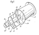
- Figure 1 is a perspective view of one embodiment of the device with its payload, prior to activation;
- Figure 2 is a perspective view of the device of Figure 1, with its payload, subsequent to activation;
- Figure 3 is a full section view of the device of Figure 1, with its payload, positioned within a pipe prior to activation;
- Figure 4 is a full section view similar to Figure 3 illustrating the device during its operation;
- Figure 5 is a full section view similar to Figures 3 and 4 of the device after operation;
- Figure 6 is a full section view similar to Figures 3, 4 and 5 subsequently to installation of the payload, illustrating the destructibility of the device;
- Figure 7 is a partial cross sectional view of a thermally activated trigger of the device;
- Figure 8 is a schemative cross-sectional view of a first alternative embodiment of the device; and
- Figures 9 to 12 are schematic cross-sectional views of second to fifth alternative embodiments respectively of the device.
- Referring to the drawings, Figure 1 illustrates the device generally at 10, carrying a payload referred to generally at 12. The
device 10 comprises acarrier 14, adriver arrangement 16, asupport arrangement 18, and a thermally activatable trigger. - The
driver arrangement 16 is connected to thecarrier 14 such as to move the carrier axially to an extended position as shown in Figure 2. Thedriver arrangement 16 comprises atelescoping cylinder 22 and apiston 24. The extension of thepiston 24 is limited by a stop 2.6, as can be more clearly seen in Figure 2. Thestop 26 is shown in a more schematic form in Figures 3-6. Thedriver arrangement 16 is, therefore, basically an expansible chamber which in the preferred embodiment comprises thecylinder 22 and thepiston 24. Thedriver arrangement 16 further comprises anenergizing fluid source 28. In the preferred embodiment, thisenergizing fluid source 28 is a chamber containing a compressed gas, e.g. air. A blowing agent may be utilized within the chamber, where said agent releases a gas or vapour at a pre-determined temperature corresponding to the temperature required to activate the trigger. The blowing agent may comprise a chemical which has a suitably low decomposition temperature and which releases a gas on decomposition, such as an azide (which releases nitrogen), or a vaporizable liquid. In either case, whether the energizing fluid source is compressed air or a blowing agent, the pressure required to drive thepiston 24 is about 2 Atmospheres. A vaporizable liquid such heptane or water has a sufficiently low boiling point that it will easily develop a vapour pressure of that magnitude. Thedriver arrangement 16 is actuated by the thermallyactivatable trigger 20, which is shown in Figure 1 as a fusible plug inserted between theenergizing fluid source 28 and thecylinder 22, within aconduit 30, as can be more clearly seen in Figure 7. When the thermallyactivatable trigger 20 is heated above its melting point it allows the energizing fluid to enter thecylinder 22. A suitable trigger will have an activation temperature, somewhat above the maximum storage temperature, but well below the activation temperature of the payload if that is heat-activated. Other configurations of theconduit 30 and theplug 20 are possible, but it is desirable that the trigger gives a rapid release of pressure into the expansible chamber to provide the maximum impulse to the piston. - The
driver arrangement 16 is supported by thesupport arrangement 18, as can be more clearly seen in Figures 3, 4 and 5. Thesupport arrangement 18 comprises a plurality of radially extending fins which are secured byflanges 32 to thecylinder 22. These fins are optimally three in number, to ensure centering and to minimize the mass of the device. Thefins 18 are further supplemented byfoldable flap portions 34, which are clearly shown in Figures 3, 4 and 5 securing theentire device 10 inpipe section 36. Thesupport arrangement 18 securely holds thedriver arrangement 16 during travel of thecarrier 14 to its predetermined location, which in this instance is the weld joiningpipe sections pipe sections ring 42, which provides a partial obstacle to movement of thecarrier 14. It is also shown in Figures 3-5 that the vicinity of the weld area containswelding debris 40. Theweld debris 40, as shown in Figure 4, may be cleaned by acleaning member 41 carried on the face of thecarrier 14. Thecleaning member 41 may comprise a brushlike member or the like which will aid in preparation of the pipe walls in the vicinity of the pre-determined location. - Figure 5 illustrates the
device 10 wherein thedriver arrangement 16 has fully extended. - It can be seen somewhat schematically in Figures 3 to 5 that an energizing fluid source has in fact expanded the driver after the thermally activated trigger has melted.
- Figure 6 illustrates that the
device 10 may be destructible after operation. Destructible as used herein includes distortable, dissolvable, dispersable, friable, frangible, and otherwise degradable so that the device may be removed from the interior of the pipe after operation by the application of heat, air pressure or by water flow. It is important, however, that even a destructible device should be capable of prolonged storage under adverse temperature and humidity conditions. - Among suitable materials for a destructible device in accordance with the present invention may be mentioned, by way of example only, the following: distortable materials - natural and synthetic rubbers; dissolvable or dispersable materials - hydroxyalkyl cellulose, polyvinyl alcohol, paper products with soluble glues; friable or frangible materials - cardboard, paper pulp, rigid foams (especially those containing a high-temperature blowing agent); vaporizable materials - thermally depoly- merizable materials such as poly (alpha-methyl styrene), polyacetals, irradiated polymers; flush- able materials (for the energizing fluid source chamber) - polyethylene, polymers of low gas permeability.
- The
carrier 14 may also perform additional shielding functions both as a shield from, for example, the heat generated in the weld area when the device is positioned as in Figure 3, and also in general as a wind barrier from wind in the pipes. Thecarrier 14 may further serve to hold the payload in alignment during operation. For example, when the payload comprises an expandable pipe liner device, thecarrier 14 may serve to align it during expansion. - Although cardboard parts will, in general, have adequate heat resistance, they (or any polymeric parts desired) may have a metallic coating applied to provide further resistance.
- Figure 8 discloses in schematic fashion the first alternative embodiment of the device, wherein the driver arrangement comprises a compressed spring-
like member 44. The spring-like member 44 is retained in compression by a compression retainer shown as collar 46 (which is connected to the inner wall of the pipe) and a trigger in the form of aclip 48 made from a thermoplastic or low-melting metallic alloy, which melts and fractures to release the spring-like member 44. - It is also possible to use one or more tensioned spring-like members (not shown). These members would be retained in tension by a mechanical tension retainer much as the
member 44 in Figure 8 is held in compression. Bands of elastomeric material, which may be heat-recoverable, will be especially suitable. - Figure 9 discloses a second alternative embodiment of the device utilizing a driver arrangement which is an expansible chamber in the form of a rolling
diaphragm chamber 50 and energizingfluid source 28. The rollingdiaphragm chamber 50 is secured to the inside of the pipe by a support in the form of aretention collar 52. The energizingfluid source 28 communicates with the rollingdiaphragm chamber 50 via a thermallyactivatable trigger 20 shown by way of example as a wax plug. - Figure 10 illustrates a third alternative embodiment of the device utilizing a driver arrangement in the form of an expansible chamber and specifically in the form of a tubular ' bellows 54, which is supported by a
retention ring 56, and is connected to energizingfluid source 28 viawax plug 20. A similar embodiment (not depicted in the drawing) may comprise an expansible chamber in the form of a balloon, where limitation on expansion either by the pipe wall or by a cylinder inside which the balloon is placed converts the volume expansion to a linear extension, moving the carrier into position. - Figure 11 illustrates a fourth alternative embodiment of the device wherein the driver arrangement comprises another compressed spring-like member in the form of rolling diaphragm chamber 58 which is retained by a compression retention device 60, much as the spring-
like member 44 is retained by thefusible clip 48 in Figure 8. The rolling diaphragm chamber 58 is a sealed chamber which contains, in the configuration of Figure 11, a pressurized fluid which will expand the chamber once released by the compression retention device 60. The compression retention device 60 will melt on heating of the pipe wall. - Figure 12 illustrates a fifth alternative embodiment of the device, similar to the device shown in Figure 11, wherein the driver arrangement comprises a tubular bellows 64 containing a fluid under pressure, said pressure being maintained by a support in the form of a
collar 66 attachable to the inside of the pipe and athermoplastic collar 68 which fractures or is thermally activated upon heating of the pipe wall. - Though the embodiments of Figures 8 to 12 have been depicted as being supported within the pipe generally be a collar-like support, it is envisaged that they may be supported by a support such as is illustrated in detail in Figures 1-5. Conversely, it is possible that the driver arrangement of the embodiments of Figures 1-5 may be supported by a simpler support. It is also envisaged that the driver arrangement may expand radially as in the case of a balloon- like chamber to contact the inside wall of a pipe for support. Indeed, the choice of support will depend much on the pipe diameter and the payload mass, and may be of any appropriate form.
- While the specification has referred extensively to positioning a payload near a pipe weld, it should be understood that the device of the invention is of general application to the placement of a payload within an inaccessible pipe by thermal activation.
Claims (11)
Priority Applications (1)
| Application Number | Priority Date | Filing Date | Title |
|---|---|---|---|
| AT81303487T ATE9835T1 (en) | 1980-07-31 | 1981-07-30 | FEED DEVICE FOR THE INTERIOR OF PIPES. |
Applications Claiming Priority (2)
| Application Number | Priority Date | Filing Date | Title |
|---|---|---|---|
| US06/174,289 US4344214A (en) | 1980-07-31 | 1980-07-31 | Internal pipe line delivery device |
| US174289 | 1980-07-31 |
Publications (2)
| Publication Number | Publication Date |
|---|---|
| EP0045628A1 EP0045628A1 (en) | 1982-02-10 |
| EP0045628B1 true EP0045628B1 (en) | 1984-10-10 |
Family
ID=22635616
Family Applications (1)
| Application Number | Title | Priority Date | Filing Date |
|---|---|---|---|
| EP81303487A Expired EP0045628B1 (en) | 1980-07-31 | 1981-07-30 | Internal pipeline delivery device |
Country Status (7)
| Country | Link |
|---|---|
| US (1) | US4344214A (en) |
| EP (1) | EP0045628B1 (en) |
| JP (1) | JPS5762894A (en) |
| AT (1) | ATE9835T1 (en) |
| CA (1) | CA1166979A (en) |
| DE (1) | DE3166613D1 (en) |
| GB (1) | GB2081837B (en) |
Cited By (1)
| Publication number | Priority date | Publication date | Assignee | Title |
|---|---|---|---|---|
| DE19946707C2 (en) * | 1999-09-29 | 2002-05-02 | Brand Gmbh & Co Kg | Suction device for suctioning liquid supernatants from open containers |
Families Citing this family (4)
| Publication number | Priority date | Publication date | Assignee | Title |
|---|---|---|---|---|
| FR2614086A1 (en) * | 1987-04-16 | 1988-10-21 | Atochem | METALLIC TUBES ASSEMBLED BY THEIR ENDS, MANUFACTURING METHOD AND APPARATUS FOR ITS IMPLEMENTATION |
| RU2250870C1 (en) * | 2003-07-30 | 2005-04-27 | Волгоградский государственный технический университет (ВолгГТУ) | Heated transport pipeline |
| US7180230B2 (en) * | 2004-04-16 | 2007-02-20 | Osram Sylvania Inc. | RF induction lamp with reduced electromagnetic interference |
| WO2011119242A2 (en) | 2010-03-24 | 2011-09-29 | Dresser-Rand Company | Press-fitting corrosion resistant liners in nozzles and casings |
Family Cites Families (11)
| Publication number | Priority date | Publication date | Assignee | Title |
|---|---|---|---|---|
| DE660158C (en) | 1934-12-07 | 1938-05-19 | Roehrenwerke Akt Ges Deutsche | Method and device for the interior lining of welded pipe connections on the construction site |
| US2564209A (en) * | 1950-01-25 | 1951-08-14 | Bendix Aviat Corp | Explosive operated motor for rip cord |
| US3425614A (en) * | 1967-05-19 | 1969-02-04 | Julius Clark | Apparatus for aligning pipe ends |
| US3750928A (en) * | 1967-09-08 | 1973-08-07 | L Valentine | Vacuum seal for internal pipeline line-up clamp |
| US3553812A (en) * | 1968-08-23 | 1971-01-12 | Galen K Weaver | Brazable terminal body and apparatus for installing same inside a tube |
| GB1426788A (en) * | 1973-11-27 | 1976-03-03 | Griffiths R P | Backing and alignment ring assembly for welding pipes |
| US3937382A (en) * | 1975-01-02 | 1976-02-10 | H. C. Price Co. | Internal pipe clamp with weld backup |
| IT1034673B (en) * | 1975-03-28 | 1979-10-10 | Saipem Spa | TUBE COUPLER TO BE HEAD WELDED |
| US4081964A (en) * | 1975-07-04 | 1978-04-04 | Dynamit Nobel Aktiengesellschaft | Apparatus for the thermal and electrical initiation of fire protection devices |
| US4195529A (en) | 1977-06-24 | 1980-04-01 | Kantsedalov Viktor G | Device for moving the pickups of a flaw detection system through a pipeline |
| FR2434330A1 (en) | 1978-08-25 | 1980-03-21 | Ato Chimie | Welded joint for metal pipe with plastic bore lining - has end zones without liner filled by coiled insert after welding |
-
1980
- 1980-07-31 US US06/174,289 patent/US4344214A/en not_active Expired - Lifetime
-
1981
- 1981-07-30 DE DE8181303487T patent/DE3166613D1/en not_active Expired
- 1981-07-30 CA CA000382851A patent/CA1166979A/en not_active Expired
- 1981-07-30 JP JP56119986A patent/JPS5762894A/en active Pending
- 1981-07-30 AT AT81303487T patent/ATE9835T1/en not_active IP Right Cessation
- 1981-07-30 GB GB8123401A patent/GB2081837B/en not_active Expired
- 1981-07-30 EP EP81303487A patent/EP0045628B1/en not_active Expired
Cited By (1)
| Publication number | Priority date | Publication date | Assignee | Title |
|---|---|---|---|---|
| DE19946707C2 (en) * | 1999-09-29 | 2002-05-02 | Brand Gmbh & Co Kg | Suction device for suctioning liquid supernatants from open containers |
Also Published As
| Publication number | Publication date |
|---|---|
| JPS5762894A (en) | 1982-04-16 |
| GB2081837B (en) | 1984-02-08 |
| ATE9835T1 (en) | 1984-10-15 |
| EP0045628A1 (en) | 1982-02-10 |
| CA1166979A (en) | 1984-05-08 |
| US4344214A (en) | 1982-08-17 |
| DE3166613D1 (en) | 1984-11-15 |
| GB2081837A (en) | 1982-02-24 |
Similar Documents
| Publication | Publication Date | Title |
|---|---|---|
| US4355664A (en) | Apparatus for internal pipe protection | |
| US4377209A (en) | Thermally activated metal hydride sensor/actuator | |
| CA2099583C (en) | Expandable holding device using a fusible alloy | |
| US4386629A (en) | Apparatus for internal pipe protection | |
| US6035898A (en) | Temporary pipeline plug | |
| CA1166979A (en) | Internal pipeline delivery device | |
| KR19990067464A (en) | Conduit lining method and apparatus | |
| CA1217799A (en) | Connecting or repair device | |
| EP1597504B1 (en) | Fire collar | |
| AU2020203895A1 (en) | Improved fire collar | |
| US4432824A (en) | Method for internal pipe protection | |
| JPS5953158B2 (en) | Explosive tube expansion device and method | |
| JP2005501681A (en) | Fire protection color | |
| CA1070773A (en) | Inert gas purge unit having flexible, expandable member | |
| JPH02247402A (en) | Sealing plug for pipe for steam generator | |
| ES2154931T3 (en) | DEVICE FOR ASSEMBLY OF AN INNER FLANGE IN A NON-ACCESSIBLE TUBE. | |
| SK133497A3 (en) | Installing a pipe in an existing pipeline | |
| US5276433A (en) | Methods and apparatus for temperature sensing | |
| WO2006034534A1 (en) | Improved fire collar | |
| CA1208047A (en) | Explosive welding device | |
| CA1214033A (en) | Method of repairing leaks in steam generator tubes | |
| JP2001121302A (en) | Pipe end machining device | |
| EP0287535B1 (en) | A method of effecting a single joint between two pipes | |
| JPS5913431Y2 (en) | Fluid transport pipe device | |
| JPS597879B2 (en) | Conduit sealing device |
Legal Events
| Date | Code | Title | Description |
|---|---|---|---|
| PUAI | Public reference made under article 153(3) epc to a published international application that has entered the european phase |
Free format text: ORIGINAL CODE: 0009012 |
|
| AK | Designated contracting states |
Designated state(s): AT BE CH DE FR IT LI NL SE |
|
| 17P | Request for examination filed |
Effective date: 19810811 |
|
| ITF | It: translation for a ep patent filed | ||
| GRAA | (expected) grant |
Free format text: ORIGINAL CODE: 0009210 |
|
| AK | Designated contracting states |
Designated state(s): AT BE CH DE FR IT LI NL SE |
|
| REF | Corresponds to: |
Ref document number: 9835 Country of ref document: AT Date of ref document: 19841015 Kind code of ref document: T |
|
| REF | Corresponds to: |
Ref document number: 3166613 Country of ref document: DE Date of ref document: 19841115 |
|
| ET | Fr: translation filed | ||
| PLBE | No opposition filed within time limit |
Free format text: ORIGINAL CODE: 0009261 |
|
| STAA | Information on the status of an ep patent application or granted ep patent |
Free format text: STATUS: NO OPPOSITION FILED WITHIN TIME LIMIT |
|
| 26N | No opposition filed | ||
| PGFP | Annual fee paid to national office [announced via postgrant information from national office to epo] |
Ref country code: AT Payment date: 19900713 Year of fee payment: 10 |
|
| PGFP | Annual fee paid to national office [announced via postgrant information from national office to epo] |
Ref country code: FR Payment date: 19900717 Year of fee payment: 10 |
|
| PGFP | Annual fee paid to national office [announced via postgrant information from national office to epo] |
Ref country code: SE Payment date: 19900718 Year of fee payment: 10 |
|
| PGFP | Annual fee paid to national office [announced via postgrant information from national office to epo] |
Ref country code: CH Payment date: 19900726 Year of fee payment: 10 |
|
| ITTA | It: last paid annual fee | ||
| PGFP | Annual fee paid to national office [announced via postgrant information from national office to epo] |
Ref country code: NL Payment date: 19900731 Year of fee payment: 10 |
|
| PGFP | Annual fee paid to national office [announced via postgrant information from national office to epo] |
Ref country code: BE Payment date: 19900808 Year of fee payment: 10 |
|
| PGFP | Annual fee paid to national office [announced via postgrant information from national office to epo] |
Ref country code: DE Payment date: 19900831 Year of fee payment: 10 |
|
| PG25 | Lapsed in a contracting state [announced via postgrant information from national office to epo] |
Ref country code: AT Effective date: 19910730 |
|
| PG25 | Lapsed in a contracting state [announced via postgrant information from national office to epo] |
Ref country code: SE Effective date: 19910731 Ref country code: LI Effective date: 19910731 Ref country code: CH Effective date: 19910731 Ref country code: BE Effective date: 19910731 |
|
| BERE | Be: lapsed |
Owner name: RAYCHEM CORP. Effective date: 19910731 |
|
| PG25 | Lapsed in a contracting state [announced via postgrant information from national office to epo] |
Ref country code: NL Effective date: 19920201 |
|
| NLV4 | Nl: lapsed or anulled due to non-payment of the annual fee | ||
| PG25 | Lapsed in a contracting state [announced via postgrant information from national office to epo] |
Ref country code: FR Effective date: 19920331 |
|
| REG | Reference to a national code |
Ref country code: CH Ref legal event code: PL |
|
| PG25 | Lapsed in a contracting state [announced via postgrant information from national office to epo] |
Ref country code: DE Effective date: 19920401 |
|
| REG | Reference to a national code |
Ref country code: FR Ref legal event code: ST |
|
| EUG | Se: european patent has lapsed |
Ref document number: 81303487.3 Effective date: 19920210 |