EP0045105B1 - Method and apparatus for the differential protection of electrical installations - Google Patents
Method and apparatus for the differential protection of electrical installations Download PDFInfo
- Publication number
- EP0045105B1 EP0045105B1 EP19810200774 EP81200774A EP0045105B1 EP 0045105 B1 EP0045105 B1 EP 0045105B1 EP 19810200774 EP19810200774 EP 19810200774 EP 81200774 A EP81200774 A EP 81200774A EP 0045105 B1 EP0045105 B1 EP 0045105B1
- Authority
- EP
- European Patent Office
- Prior art keywords
- current
- measuring
- differential
- signal
- limit
- Prior art date
- Legal status (The legal status is an assumption and is not a legal conclusion. Google has not performed a legal analysis and makes no representation as to the accuracy of the status listed.)
- Expired
Links
Images

Classifications
-
- H—ELECTRICITY
- H02—GENERATION; CONVERSION OR DISTRIBUTION OF ELECTRIC POWER
- H02H—EMERGENCY PROTECTIVE CIRCUIT ARRANGEMENTS
- H02H3/00—Emergency protective circuit arrangements for automatic disconnection directly responsive to an undesired change from normal electric working condition with or without subsequent reconnection ; integrated protection
- H02H3/26—Emergency protective circuit arrangements for automatic disconnection directly responsive to an undesired change from normal electric working condition with or without subsequent reconnection ; integrated protection responsive to difference between voltages or between currents; responsive to phase angle between voltages or between currents
- H02H3/28—Emergency protective circuit arrangements for automatic disconnection directly responsive to an undesired change from normal electric working condition with or without subsequent reconnection ; integrated protection responsive to difference between voltages or between currents; responsive to phase angle between voltages or between currents involving comparison of the voltage or current values at two spaced portions of a single system, e.g. at opposite ends of one line, at input and output of apparatus
- H02H3/283—Emergency protective circuit arrangements for automatic disconnection directly responsive to an undesired change from normal electric working condition with or without subsequent reconnection ; integrated protection responsive to difference between voltages or between currents; responsive to phase angle between voltages or between currents involving comparison of the voltage or current values at two spaced portions of a single system, e.g. at opposite ends of one line, at input and output of apparatus and taking into account saturation of current transformers
-
- H—ELECTRICITY
- H02—GENERATION; CONVERSION OR DISTRIBUTION OF ELECTRIC POWER
- H02H—EMERGENCY PROTECTIVE CIRCUIT ARRANGEMENTS
- H02H7/00—Emergency protective circuit arrangements specially adapted for specific types of electric machines or apparatus or for sectionalised protection of cable or line systems, and effecting automatic switching in the event of an undesired change from normal working conditions
- H02H7/04—Emergency protective circuit arrangements specially adapted for specific types of electric machines or apparatus or for sectionalised protection of cable or line systems, and effecting automatic switching in the event of an undesired change from normal working conditions for transformers
- H02H7/045—Differential protection of transformers
- H02H7/0455—Differential protection of transformers taking into account saturation of current transformers
Definitions
- the invention relates to a method for the differential protection of electrical systems according to the preamble of claim 1.
- the invention further relates to a device for performing such a method with both sides of the object to be protected in the circuit to be monitored, current measuring elements arranged on a Difference formers for the generation of a residual current signal with a downstream monitoring circuit are connected.
- the invention relates to a prior art of methods and devices for the differential protection of electrical systems, as described in DE-A-2339931.
- a measurement variable residual current signal, tripping quantity
- a measurement quantity corresponding to the geometric sum of the currents flowing into the line section and the currents flowing out of the line section
- a measurement quantity corresponding to the arithmetic sum of the inflowing and outflowing currents sum current signal, blocking quantity
- the residual current signal therefore remains approximately zero for a certain time after the short circuit occurs. Only when at least one current transformer saturates does the residual current signal become non-zero. In the case of an internal short circuit, however, the residual current signal is immediately not equal to zero.
- the measuring interval of the differential protection is determined by the running time of a monostable multivibrator. The duration of this measurement interval is at least 1.5 ms after a short circuit occurs. During this measurement interval, it is determined whether the short-circuit is internal or external. If there is an external short circuit, the triggering of an error signal or a trip element is blocked for several periods. The protection will slow down due to a long-term blocking of the release. An external error can lead to an internal error due to a rollover, which is then noticed only late.
- Differential protection methods and corresponding devices of the aforementioned type are also known from «Selective protection of electrical systems •, Leonhard Müller, 1971, publishing and business company of Elektrizticianstechnike mbH, Frankfurt / Main, pages 78-83.
- This is differential protection in the narrower sense, i.e. H. around the differential protection of a protected object arranged in a simple cable run, whereby in contrast to the busbar protection only two measuring currents on both sides of the protected object are to be detected.
- a differential current signal can be formed as a measure of the difference between the current flowing to and from the protected object in a simple manner as the difference between the current signal rated with the same sign in a flow direction of the cable run.
- the invention solves the problem of specifying a faster differential protection which is insensitive to converter saturations.
- An advantage of the invention is the greater certainty of error detection, since differential currents below a predefinable limit value are not detected by the error evaluation. After an external error has occurred, a new error can be recorded after just one period.
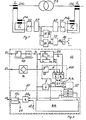
- a line section running via a transformer TR as a protected object is delimited by current transformers SW 1 , SW 2 .
- the counting parts of the line current I are selected in the same direction according to the direction of flow in the trouble-free operation.
- ZW 2 results in corresponding current signals 1 1 and 1 2, which is also conventional per se star-delta converter SU and AP matching circuits a Summenstromsentner SI and DI are supplied to a Differenzstromstoryner.
- the differential or sum current signal ⁇ I or ⁇ l obtained therefrom is fed to a monitoring circuit US with a trigger element AS for the fault shutdown.
- the total current signal ⁇ I first arrives at a zero-crossing detector ND, which consists of a trigger with a subsequent monoflop and delivers a pulse-shaped clock signal s o at the zero-current crossings to mark the start of each current half-period to be monitored.
- These clock signals trigger a timer ZG, which determines two sampling intervals T 1 and T 2 , starting in each case with the start time t o of a half-period.
- a sampling signal s 1 or s 2 appears at the outputs of the timer at separate outputs.
- the two sampling intervals with their start and end times are indicated diagrammatically.
- the differential current signal .DELTA.I supplied to the monitoring circuit US reaches a limit value comparison and sampling circuit GVA via a full-wave rectifier G, which is also acted upon by the sampling signals s 1 and s 2 .
- the differential current signal is first checked by means of a limit switch GS for exceeding a limit value signal or threshold value that excludes the interference level and, if the limit value is exceeded, converted into a binary difference signal d. The latter is then successively scanned in two AND gates AG 1 and AG 2 by the signals s 1 and S2 .
- corresponding pulse-shaped limit value violation signals p 1 or p 2 result , which overlap in time in an OR gate OG are supplied as switching signals to an input C of a shift register SP provided as a memory circuit.
- This register comprises three stages a, b and c, stage a being activated in the initial state by a reset signal s o 'via a reset input R of the shift register.
- This reset signal is produced with a slight time delay T o of for example less than one millisecond by a respective timing element Z from the clock signals s o.
- stages b or c of the shift register are activated in succession and thus the one or two occurrences of limit value exceeding of the differential current signal are marked at the sampling times.
- the result of this scanning is determined by an interrogation circuit AF and, if necessary, a two-fold exceeding of the limit value within a half-period is converted into an error signal or trigger signal sa as a sign of an internal error.
- the output of the shift register stage c is connected via an AND gate AG 3 to a dynamic set input of a binary memory element FF 1 , which delivers the trigger signal mentioned in the set state.
- the reset after a fault shutdown takes place in a conventional manner via an external reset channel ER.
- stage b of the shift register is activated.
- a trigger signal is not generated here, but the monitoring or triggering should be blocked in the next half-cycle because in such a subsequent half-cycle there is generally also a saturation Residual current of considerable size occurs immediately after the initial zero crossing and could lead to false tripping.
- the output of stage b is queried in a blocking circuit BK for a clock signal s o and converted into a blocking signal, not shown.
- This blocking signal is held in the blocking circuit BK in such a way that an enable signal sf which normally occurs at the output of this blocking circuit is inhibited.
- This enable signal is normally on the already mentioned AND gate AG 3 and enables the setting of the memory element FF 1 with the generation of the trigger signal sa.
- the blocking signal is canceled by the reset signal s 0 'and the release signal sf is reactivated.
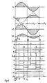
- the measuring current signals 1 1 and 1 2 as well as the differential current signal ⁇ I and total current signal ⁇ I for three successive half-waves H 1 , H 2 and H 3 are shown for the occurrence of an error-related differential current or a saturation-related differential current.
- the time profiles of the various signals are shown in association with the aforementioned current signals, analogously for fault-related residual current with generation of a trigger signal sa and for saturation-related residual current without generation of such a signal .
- the sequence and assignment of the various signals are indicated by means of continuous, vertical marking lines and corresponding action arrows in accordance with the explained mode of operation of the monitoring circuit.
- the two sampling times t 1 and t 2 each lie within the first and second half of a measuring current half cycle.
- a setting of t 1 in a time range between 2 and 3 ms and for t 2 in a time range between 5 and 8 ms after the start of the respective half-period has proven particularly expedient.
Landscapes
- Engineering & Computer Science (AREA)
- Power Engineering (AREA)
- Emergency Protection Circuit Devices (AREA)
Description
Die Erfindung bezieht sich auf ein Verfahren für den Differentialschutz von elektrischen Anlagen nach dem Oberbegriff des Anspruchs 1. Die Erfindung bezieht sich ferner auf eine Einrichtung zur Durchführung eines solchen Verfahrens mit beiderseits des Schutzobjektes in dem zu überwachenden Stromkreis angeordneten Strom-Messgliedern, die an einen Differenzbildner für die Erzeugung eines Differenzstromsignals mit nachgeordneter Überwachungsschaltung angeschlossen sind.The invention relates to a method for the differential protection of electrical systems according to the preamble of
Mit dem Oberbegriff nimmt die Erfindung auf einen Stand der Technik von Verfahren und Einrichtungen für den Differentialschutz von elektrischen Anlagen Bezug, wie er in der DE-A-2339931 beschrieben ist. Dort wird zur Überwachung eines Leitungsabschnittes eine der geometrischen Summe der dem Leitungsabschnitt zufliessenden Ströme und der aus dem Leitungsabschnitt abfliessenden Ströme entsprechende Messgröse (Differenzstromsignal, Auslösegrösse) und eine der arithmetischen Summe der zu- und abfliessenden Ströme entsprechende Messgrösse (Summenstromsignal, Sperrgrösse) verwendet. Dabei ist von der Erkenntnis ausgegangen, dass zur Strommessung verwendete Stromwandler nach Eintritt eines Kurzschlusses nicht sofort gesättigt sind, sondern den Primärstrom noch eine kurze Zeit unverändert übertragen. Im Falle eines äusseren Kurzschlusses bleibt daher das Differenzstromsignal nach Eintritt des Kurzschlusses noch eine gewisse Zeit annähernd Null. Erst wenn mindestens ein Stromwandler in die Sättigung gerät, wird das Differenzstromsignal ungleich Null. Im Falle eines innenligenden Kurzschlusses ist dagegen das Differenzstromsignal sofort ungleich Null. Das Messintervall des Differentialschutzes ist durch die Laufzeit einer monostabilen Kippstufe vorgegeben. Die Dauer dieses Messintervalls beträgt mindestens 1,5 ms nach Eintritt eines Kurzschlusses. Während dieses Messintervalls wird bestimmt, ob es sich um einen innen- oder aussenliegenden Kurzschluss handelt. Wenn es sich um einen aussenliegenden Kurzschluss handelt, wird die Auslösung eines Fehlersignals oder eines Auslösegliedes während mehrerer Perioden gesperrt. Durch eine langzeitige Sperrung der Auslösung wird der Schutzlangsam. Ein aussenliegender Fehler kann durch Überschlag zu einem innenliegenden Fehler führen, der dann erst spät bemerkt wird.With the preamble, the invention relates to a prior art of methods and devices for the differential protection of electrical systems, as described in DE-A-2339931. For monitoring a line section, a measurement variable (residual current signal, tripping quantity) corresponding to the geometric sum of the currents flowing into the line section and the currents flowing out of the line section, and a measurement quantity corresponding to the arithmetic sum of the inflowing and outflowing currents (sum current signal, blocking quantity) are used. It is based on the knowledge that current transformers used for current measurement are not immediately saturated after a short circuit occurs, but rather transmit the primary current unchanged for a short time. In the case of an external short circuit, the residual current signal therefore remains approximately zero for a certain time after the short circuit occurs. Only when at least one current transformer saturates does the residual current signal become non-zero. In the case of an internal short circuit, however, the residual current signal is immediately not equal to zero. The measuring interval of the differential protection is determined by the running time of a monostable multivibrator. The duration of this measurement interval is at least 1.5 ms after a short circuit occurs. During this measurement interval, it is determined whether the short-circuit is internal or external. If there is an external short circuit, the triggering of an error signal or a trip element is blocked for several periods. The protection will slow down due to a long-term blocking of the release. An external error can lead to an internal error due to a rollover, which is then noticed only late.
Differentialschutzverfahren und entsprechende Einrichtungen der vorgenannten Art sind ferner bekannt aus « Selektivschutz elektrischer Anlagen •, Leonhard Müller, 1971, Verlags- und Wirtschaftsgesellschaft der Elektrizitätswerke mbH, Frankfurt/Main, Seiten 78-83. Es handelt sich hier um den Differentialschutz im engeren Sinne, d. h. um den Differentialschutz eines in einem einfachen Leitungszug angeordneten Schutzobjektes, wobei also im Gegensatz zum Sammelschienenschutz nur zwei Messströme beiderseits des Schutzobjektes zu erfassen sind. Hier kann ein Differenzstromsignal als Mass der Differenz des jeweils dem Schutzobjekt zufliessenden und von diesem abfliessenden Stromes in einfacher Weise als Differenz der in einer Durchströmrichtung des Leitungszuges mit übereinstimmenden Vorzeichen bewerteten Stromsignals gebildet werden.Differential protection methods and corresponding devices of the aforementioned type are also known from «Selective protection of electrical systems •, Leonhard Müller, 1971, publishing and business company of Elektrizitätswerke mbH, Frankfurt / Main, pages 78-83. This is differential protection in the narrower sense, i.e. H. around the differential protection of a protected object arranged in a simple cable run, whereby in contrast to the busbar protection only two measuring currents on both sides of the protected object are to be detected. Here, a differential current signal can be formed as a measure of the difference between the current flowing to and from the protected object in a simple manner as the difference between the current signal rated with the same sign in a flow direction of the cable run.
Dies ist beim Sammelschienenschutz mit einer Vielzahl von mit wechselnder Durchströmrichtung bzw. Energieübertragungsrichtung betreibbaren Abgängen nicht ohne weiteres möglich, weshalb dort an die Stelle einer Differenzstrombildung sinngemäss eine vektorielle Summenstrombildung mit übereinstimmender Vorzeichenbewertung in Zuströmrichtung oder Abströmrichtung für alle betroffenen Abgänge tritt. Bei allen diesen Schutzverfahren ist der Differenzstrom bezüglich der Durchströmrichtung bzw. der vektorielle Summenstrom in Zuström- oder Abströmrichtung im störungsfreien Fall Null, weshalb grundsätzlich das Problem der Vortäuschung eines Kurzschlusses durch einseitige bzw. unsymmetrische Wandlersättigung an den Strom-Messgliedern besteht. Solche Fehlauslösungen werden u. a. von hohen Durchgangsströmen verursacht, wie sie bei aussenliegenden Kurzschlüssen auftreten können.This is not easily possible with busbar protection with a large number of outlets that can be operated with changing flow direction or energy transfer direction, which is why there is a vectorial total current formation with a corresponding sign evaluation in the inflow direction or outflow direction for all affected outlets instead of the formation of a residual current. In all of these protection methods, the residual current with respect to the flow direction or the vectorial total current in the inflow or outflow direction is zero in the case of a fault, which is why there is basically the problem of simulating a short circuit due to one-sided or asymmetrical transformer saturation on the current measuring elements. Such false trips are u. a. caused by high through currents, as can occur with external short circuits.
Dem Problem dieser Fehlauslösungen kann in bekannter Weise durch Stabilisierung des Differentialschutzes entgegengewirkt werden, beispielsweise durch Einführung eines der Auslösung entgegenwirkenden Haltesystems, das mit der geometrischen Summe der (wiederum in Durchströmrichtung gleichermassen mit übereinstimmendem Vorzeichen bewerteten) Ströme beiderseits des Schutzobjektes gespeist wird. Wegen der damit verbundenen Empfindlichkeitsverminderung gegenüber Differenzströmen, die beispielsweise bei Windungs- oder Lagenkurzschluss in Transformatoren und Generatoren vergleichsweise gering bleiben, ist darüberhinaus eine Anpassung der Differenzstrom-Auslösekennlinien mit nichtlinearem Verlauf an die Verhältnisse bei verschiedenen Differenzstrombereichen bekannt geworden (siehe die vorgenannte Literaturstelle). Alle diese Lösungen sind mit mehr oder weniger grossem Aufwand verbunden und erhöhen nach wie vor grundsätzlich im Bereich grösserer Empfindlichkeit die Gefahr von Fehlauslösungen, während in dem Kennlinienbereich mit geringerer Empfindlichkeit eine verminderte Kurzschluss-Abschaltsicherheit in Kauf genommen werden muss.The problem of this false triggering can be counteracted in a known manner by stabilizing the differential protection, for example by introducing a holding system counteracting the triggering, which is fed with the geometric sum of the currents (again in the flow direction equally valued with the same sign) on both sides of the protected object. Because of the associated reduction in sensitivity to residual currents, which remain comparatively low, for example in the event of a short-circuit or short-circuit in transformers and generators, an adaptation of the residual current tripping characteristics with a non-linear curve to the conditions at different residual current ranges has also become known (see the aforementioned literature reference). All of these solutions are associated with more or less great effort and, as before, generally increase the risk of false tripping in the area of greater sensitivity, while in the characteristic area with less sensitivity, reduced short-circuit shutdown safety must be accepted.
Ausserdem ist dem Problem der Differenzstrom-Vortäuschung durch Wandlersättigung noch durch Stabilisierung der Strom-Kurvenform mit Hilfe von Integratoren entgegengetreten worden, die den einmal erreichten Stromsignalwert unabhängig von einem Abfall durch Wandlersättigung aufrecht erhalten (siehe Brown Boveri Mitteilungen, Band 53, 1966, Nr. 4/5, Seite 330, rechte Spalte). Diese Lösung macht jedoch eine besondere Integrator-Rückstellung bei den jeweils nachfolgenden Nulldurchgängen erforderlich und ist daher wiederum mit an sich unerwünscht hohem Aufwand verbunden.In addition, the problem of differential current pretense through transformer saturation has been countered by stabilizing the current waveform with the help of integrators, which maintain the current signal value once reached regardless of a drop due to transformer saturation (see Brown Boveri Mittei lung, Volume 53, 1966, No. 4/5, page 330, right column). However, this solution requires a special integrator reset for the subsequent zero crossings and is therefore in turn associated with an undesirably high outlay.
Die Erfindung, wie sie in den Ansprüchen gekennzeichnet ist, löst die Aufgabe, einen schnelleren Differentialschutz anzugeben, der gegenüber Wandlersättigungen unempfindlich ist.The invention, as characterized in the claims, solves the problem of specifying a faster differential protection which is insensitive to converter saturations.
Ein Vorteil der Erfindung besteht in der grösseren Sicherheit der Fehlererfassung, da Differenzströme unterhalb eines vorgebbaren Grenzwerts von der Fehlerauswertung nicht erfasst werden. Nach einem Auftreten eines aussenliegenden Fehlers wird bereits nach einer Periode die Erfassung eines neuen Fehlers möglich.An advantage of the invention is the greater certainty of error detection, since differential currents below a predefinable limit value are not detected by the error evaluation. After an external error has occurred, a new error can be recorded after just one period.
Weitere Merkmale und Vorteile der Erfindung werden anhand eines in den Zeichnungen dargestellten Ausführungsbeispiels erläutert. Hierin zeigt :
Figur 1 ein Übersichtsschaltbild eines Differentialschutzes für einen Transformator mit einer erfindungsgemässen Differenzstrom-Überwachungsschaltung,Figur 2 das Wirkschaltbild der Differenzstrom- Überwachungsschaltung und- Figur 3 bzw. Figur 4 je ein Mehrfach-Signal-Zeitdiagramm zur Arbeitsweise der Überwachungsschaltung bei fehlerbedingtem bzw. sättigungsbedingtem Differenzstromsignal.
- 1 shows an overview circuit diagram of a differential protection for a transformer with a differential current monitoring circuit according to the invention,
- Figure 2 shows the circuit diagram of the residual current monitoring circuit and
- FIG. 3 or FIG. 4 each show a multiple signal timing diagram for the mode of operation of the monitoring circuit in the event of an error-related or saturation-related differential current signal.
In der Schaltung nach Fig. 1 ist ein über einen Transformator TR als Schutzobjekt verlaufender Leitungsabschnitt durch Strom-Wandler SW1, SW2 abgegrenzt. Die Zählpleile des Leitungsstromes I sind entsprechend der Durchströmrichtung im störungsfreien Betrieb gleichsinnig gewählt. Über übliche Zwischenwandler ZW1, ZW2 ergeben sich entsprechende Stromsignale 11 und 12, die über ebenfalls an sich übliche Stern-Dreieckumsetzer SU sowie Anpassschaltungen AP einem Summenstrombildner SI und einem Differenzstrombildner DI zugeführt werden. Das hieraus erhaltene Differenz- bzw. Summenstromsignal ΔI bzw. Σl wird einer Überwachungsschaltung US mit Auslöseglied AS für die Fehlerabschaltung zugeführt.In the circuit according to FIG. 1, a line section running via a transformer TR as a protected object is delimited by current transformers SW 1 , SW 2 . The counting parts of the line current I are selected in the same direction according to the direction of flow in the trouble-free operation. Via common intermediate ZW converter 1, ZW 2 results in corresponding
Nach Fig. 2 gelangt das Summenstromsignal ΣI zunächst an einen Nulldurchgangs-Detektor ND, der aus einem Trigger mit nachfolgendem Monoflop besteht und bei den Strom-Nulldurchgängen je ein impulsförmiges Taktsignal so zur Markierung des Beginnes einer jeden zu überwachenden Strom-Halbperiode liefert. Durch diese Taktsignale wird ein Zeitgeber ZG angesteuert, der jeweils beginnend mit dem Startzeitpunkt to einer Halbperiode zwei Abtastintervalle T1 und T2 bestimmt. Zum Endzeitpunkt t1 bzw. t2 der beiden Abtastintervalle erscheint am Ausgang des Zeitgebers an getrennten Ausgängen ein Abtastsignal s1 bzw. s2. Im Schaltungsblock von ZG sind die beiden Abtastintervalle mit ihren Start- und Endzeitpunkten diagrammartig angedeutet.According to FIG. 2, the total current signal ΣI first arrives at a zero-crossing detector ND, which consists of a trigger with a subsequent monoflop and delivers a pulse-shaped clock signal s o at the zero-current crossings to mark the start of each current half-period to be monitored. These clock signals trigger a timer ZG, which determines two sampling intervals T 1 and T 2 , starting in each case with the start time t o of a half-period. At the end point in time t 1 or t 2 of the two sampling intervals, a sampling signal s 1 or s 2 appears at the outputs of the timer at separate outputs. In the ZG circuit block, the two sampling intervals with their start and end times are indicated diagrammatically.
Das der Überwachungsschaltung US zugeführte Differenzstromsignal ΔI gelangt über einen Vollweg-Gleichrichter G an eine Grenzwertvergleichs- und Abtastschaltung GVA, die auch mit den Abtastsignalen s1 und s2 beaufschlagt wird. Innerhalb dieser Schaltung wird zunächst das Differenzstromsignal mittels eines Grenzwertschalters GS auf Überschreitung eines den Störpegel ausschliessenden Grenzwertsignals bzw. Schwellenwertes geprüft und bei Grenzwertüberschreitung in ein binäres Differenzsignal d umgesetzt. Letzteres wird sodann in zwei Und-Gattern AG1 und AG2 durch die Signale s1 und S2 aufeinanderfolgend abgetastet. Sofern zu den Abtastzeipunkten t1 bzw. t2 eine Grenzwertüberschreitung des Differenzstromsignals und damit ein entsprechender binärer Wert des Differenzsignals d vorliegt, ergeben sich entsprechende, impulsförmige Grenzwert-Überschreitungssignale p1 bzw. p2, die in einem Oder-Gatter OG zeitlich überlagert und als Schaltsignale einem Eingang C eines als Speicherschaltung vorgesehenen Schieberegisters SP zugeführt werden. Dieses Register umfasst drei Stufen a, b und c, wobei die Stufe a im Ausganszustand durch ein Rückstellsignal so' über einen Rückstelleingang R des Schieberegisters aktiviert wird. Dieses Rückstellsignal wird mit einer geringfügigen Zeitverzögerung To von beispielsweise unter einer Millisekunde mittels eines entsprechenden Zeitgliedes Z aus den Taktsignalen so erzeugt.The differential current signal .DELTA.I supplied to the monitoring circuit US reaches a limit value comparison and sampling circuit GVA via a full-wave rectifier G, which is also acted upon by the sampling signals s 1 and s 2 . Within this circuit, the differential current signal is first checked by means of a limit switch GS for exceeding a limit value signal or threshold value that excludes the interference level and, if the limit value is exceeded, converted into a binary difference signal d. The latter is then successively scanned in two AND gates AG 1 and AG 2 by the signals s 1 and S2 . If there is a limit value violation of the differential current signal and thus a corresponding binary value of the difference signal d at the sampling point t 1 or t 2 , corresponding pulse-shaped limit value violation signals p 1 or p 2 result , which overlap in time in an OR gate OG are supplied as switching signals to an input C of a shift register SP provided as a memory circuit. This register comprises three stages a, b and c, stage a being activated in the initial state by a reset signal s o 'via a reset input R of the shift register. This reset signal is produced with a slight time delay T o of for example less than one millisecond by a respective timing element Z from the clock signals s o.
Bei Auftreten von Grenzwert-Überschreitungssignalen p1 bzw. p2 werden nacheinander die Stufen b bzw. c des Schieberegisters aktiviert und damit das einmalige oder zweimalige Auftreten von Grenzwertüberschreitungen des Differenzstromsignals zu den Abtastzeitpunkten markiert. Das Ergebnis dieser Abtastung wird durch eine Abfrageschaltung AF festgestellt und gegebenenfalls eine zweimalige Grenzwertüberschreitung innerhalb einer Halbperiode als Kennzeichen für einen inneren Fehler in ein Fehlersignal bzw. Auslösesignal sa umgesetzt. Hierzu ist der Ausgang der Schieberegisterstufe c über ein Und-Gatter AG3 an einen dynamischen Setzeingang eines binären Speichergliedes FF1 angeschlossen, welches im Setzzustand das erwähnte Auslösesignal saliefert. Die Rücksetzung nach Fehlerabschaltung erfolgt in an sich üblicher Weise über einen externen Rückstellkanal ER.If limit value exceeding signals p 1 or p 2 occur , stages b or c of the shift register are activated in succession and thus the one or two occurrences of limit value exceeding of the differential current signal are marked at the sampling times. The result of this scanning is determined by an interrogation circuit AF and, if necessary, a two-fold exceeding of the limit value within a half-period is converted into an error signal or trigger signal sa as a sign of an internal error. For this purpose, the output of the shift register stage c is connected via an AND gate AG 3 to a dynamic set input of a binary memory element FF 1 , which delivers the trigger signal mentioned in the set state. The reset after a fault shutdown takes place in a conventional manner via an external reset channel ER.
Bei nur einmaligem Auftreten einer Grenzwertüberschreitung des Differenzstromsignals wird innerhalb einer Halbperiode lediglich ein Grenzwert-Überschreitungssignal P2 zum Zeitpunkt t2 erzeugt und damit nur die Stufe b des Schieberegisters aktiviert. Dies bedeutet das Auftreten eines Differenzstromes infolge Wandlersättigung bei aussenliegendem Fehler. Ein Auslösesignal wird hierbei nicht erzeugt, jedoch soll die Überwachung oder Auslösung in der jeweils nächstfolgenden Halbperiode gesperrt werden, weil in einer solchen nachfolgenden Halbperiode im allgemeinen auch ein Sättigungs-Differenzstrom beträchtlicher Grösse unmittelbar nach dem Anfangs-Nulldurchgang auftritt und zu einer Fehlauslösung führen könnte. Hierzu wird der Ausgang der Stufe b in einer Blockierschaltung BK jeweils bei einem Taktsignal so abgefragt und in ein nicht dargestelltes Blockiersignal umgesetzt. Dieses Blockiersignal wird in der Blockierschaltung BK in der Weise festgehalten, dass ein im Normalfall am Ausgang dieser Blockierschaltung auftretendes Freigabesignal sf inhibiert wird. Dieses Freigabesignal liegt im Normalfall am bereits erwähnten Und-Gatter AG3 und ermöglicht das Setzen des Speichergliedes FF1 mit Erzeugung des Auslösesignals sa. Jeweils nach Ablauf der betreffenden Halbperiode wird das Blockiersignal durch das Rückstellsignal s0' aufgehoben sowie das Freigabesignal sf wieder aktiviert.If the limit current signal of the differential current signal is exceeded only once within a half period, only a limit value exceeding signal P2 is generated at the time t 2 and thus only the stage b of the shift register is activated. This means the occurrence of a differential current due to transformer saturation with an external fault. A trigger signal is not generated here, but the monitoring or triggering should be blocked in the next half-cycle because in such a subsequent half-cycle there is generally also a saturation Residual current of considerable size occurs immediately after the initial zero crossing and could lead to false tripping. For this purpose, the output of stage b is queried in a blocking circuit BK for a clock signal s o and converted into a blocking signal, not shown. This blocking signal is held in the blocking circuit BK in such a way that an enable signal sf which normally occurs at the output of this blocking circuit is inhibited. This enable signal is normally on the already mentioned AND gate AG 3 and enables the setting of the memory element FF 1 with the generation of the trigger signal sa. Each time after the relevant half-period has elapsed, the blocking signal is canceled by the reset signal s 0 'and the release signal sf is reactivated.
In den Zeitdiagrammen gemäss Fig. und 4 sind jeweils für das Auftreten eines fehlerbedingten Differenzstromes bzw. eines sättigungsbedingten Differenzstromes die Messstromsignale 11 und 12 sowie das Differenzstromsignal ΔI und Summenstromsignal ΣI für drei aufeinanderfolgende Halbwellen H1, H2 und H3 dargestellt. In den weiteren Diagrammzeilen sind die Zeitverläufe der verschiedenen Signale, wie vorstehend anhand der Schaltung nach Fig. 2 erläutert, in Zuordnung zu den vorgenannten Stromsignalen dargestellt, und zwar sinngemäss für fehlerbedingten Differenzstrom mit Erzeugung eines Auslösesignals sa sowie für sättigungsbedingten Differenzstrom ohne Erzeugung eines solchen Signals. Der Ablauf und die Zuordnung der verschiedenen Signale sind mittels durchgehender, vertikaler Markierungslinien und entsprechender Wirkungspfeile in Übereinstimmung mit der erläuterten Arbeitsweise der Überwachungsschaltung angedeutet.In the time diagrams according to FIGS. 4 and 4, the measuring
Die beiden Abtastzeitpunkte t1 und t2 liegen, wie aus den Diagrammzeilen für s1 und s2 hervorgeht, jeweils innerhalb der ersten und zweiten Hälfte einer Messstromhalbperiode. Erfahrungsgemäss hat sich eine Einstellung von t1 in einem Zeitbereich zwischen 2 und 3 ms sowie für t2 in einem Zeitbereich zwischen 5 und 8 ms nach Beginn der jeweiligen Halbperiode als besonders zweckmässig erwiesen.As can be seen from the diagram lines for s 1 and s 2 , the two sampling times t 1 and t 2 each lie within the first and second half of a measuring current half cycle. Experience has shown that a setting of t 1 in a time range between 2 and 3 ms and for t 2 in a time range between 5 and 8 ms after the start of the respective half-period has proven particularly expedient.
Claims (7)
characterised in
Applications Claiming Priority (2)
| Application Number | Priority Date | Filing Date | Title |
|---|---|---|---|
| CH5752/80 | 1980-07-28 | ||
| CH575280 | 1980-07-28 |
Publications (2)
| Publication Number | Publication Date |
|---|---|
| EP0045105A1 EP0045105A1 (en) | 1982-02-03 |
| EP0045105B1 true EP0045105B1 (en) | 1984-11-28 |
Family
ID=4298750
Family Applications (1)
| Application Number | Title | Priority Date | Filing Date |
|---|---|---|---|
| EP19810200774 Expired EP0045105B1 (en) | 1980-07-28 | 1981-07-07 | Method and apparatus for the differential protection of electrical installations |
Country Status (2)
| Country | Link |
|---|---|
| EP (1) | EP0045105B1 (en) |
| DE (1) | DE3167445D1 (en) |
Families Citing this family (4)
| Publication number | Priority date | Publication date | Assignee | Title |
|---|---|---|---|---|
| FR2601524B1 (en) * | 1986-07-08 | 1993-09-17 | Equip Elect Cie Continen | METHOD FOR MONITORING INTERNAL FAULTS OF ELECTRICAL EQUIPMENT AND DEVICE FOR CARRYING OUT SAID METHOD |
| AT391230B (en) * | 1986-08-20 | 1990-09-10 | Elin Union Ag | DEVICE FOR DETECTING THE ZERO TRANSITIONS |
| DE3905335A1 (en) * | 1989-02-22 | 1990-08-23 | Licentia Gmbh | METHOD AND DEVICE FOR GENERATING TRIGGER SIGNALS FOR SWITCHES FOR SHORT-CIRCUITS ON BUSBARS AND / OR BUSBAR SECTIONS |
| US5627712A (en) * | 1990-04-19 | 1997-05-06 | General Electric Company | Transformer differential relay |
Family Cites Families (3)
| Publication number | Priority date | Publication date | Assignee | Title |
|---|---|---|---|---|
| FR2239791A1 (en) * | 1973-08-03 | 1975-02-28 | Siemens Ag | Determination of faults in electrical power transmission links - by monitoring during selected intervals in each half cycle |
| FR2363925A1 (en) * | 1976-08-31 | 1978-03-31 | Schlumberger Compteurs | Protection circuit for nodal point in power distribution system - isolates node when fault appears and one coupling transformer saturates |
| DE2905195C2 (en) * | 1979-02-12 | 1985-04-04 | Licentia Patent-Verwaltungs-Gmbh, 6000 Frankfurt | Differential protection device |
-
1981
- 1981-07-07 EP EP19810200774 patent/EP0045105B1/en not_active Expired
- 1981-07-07 DE DE8181200774T patent/DE3167445D1/en not_active Expired
Also Published As
| Publication number | Publication date |
|---|---|
| EP0045105A1 (en) | 1982-02-03 |
| DE3167445D1 (en) | 1985-01-10 |
Similar Documents
| Publication | Publication Date | Title |
|---|---|---|
| EP0721684B1 (en) | Method of generating a fault-indication signal | |
| DE2308489C3 (en) | Method and device for localizing the fault location on lines | |
| DE69414605T2 (en) | DIFFERENTIAL PROTECTIVE DEVICE FOR A POWER TRANSFORMER | |
| DE4021522A1 (en) | ELECTRONIC SWITCH | |
| DE2256536A1 (en) | PROCEDURE AND ARRANGEMENT FOR LOCATING A FAULT ON AN ELECTRIC POWER TRANSPORT LINE | |
| DE2530717A1 (en) | METHOD AND DEVICE FOR DISCONNECTING AN ELECTRICAL TRANSMISSION LINE IN THE EVENT OF OVERLOAD | |
| DE2609654A1 (en) | DIGITAL OVERCURRENT RELEASE | |
| DE4420513A1 (en) | Protecting bus=bars using constant k with value greater than k equal to 2 outputs | |
| EP0045105B1 (en) | Method and apparatus for the differential protection of electrical installations | |
| DE1956527C3 (en) | Differential protection device | |
| DE2414556A1 (en) | METHOD FOR CONNECTING A STATIC INVERTER IN PARALLEL WITH AN ELECTRICAL AC VOLTAGE SOURCE AND LOGIC DEVICES FOR USING THIS METHOD | |
| DE2264064A1 (en) | DISTANCE PROTECTION DEVICE | |
| DE2753517A1 (en) | METHOD AND DEVICE FOR DETECTING FAULT CURRENTS | |
| DE4026799A1 (en) | Selective detection of faults in conductors in high voltage network - by comparing conductor voltages and currents with earth current and star earth voltage | |
| DE2819204C2 (en) | Circuit arrangement for a direct current and / or alternating current sensitive residual current protective circuit provided with an amplifier | |
| DE2134920A1 (en) | PROCEDURE AND EQUIPMENT FOR PROTECTION OF DC TRANSMISSION LINES | |
| EP0046317B1 (en) | Process and arrangement for detecting the direction of a short circuit | |
| DE1905505B2 (en) | FAULT CIRCUIT BREAKER | |
| DE1537532C3 (en) | m-out-n connection | |
| DE2708844C3 (en) | Protection device for a generator-turbine unit against overloading of the shaft | |
| DE19944680C2 (en) | Device for phase error detection | |
| DE19741662C2 (en) | Procedure for fully selective reserve protection in cable networks | |
| DE2216377B2 (en) | Differential protection | |
| DE19612992C2 (en) | Method for detecting a fault on a section of an electrical power supply line delimited by circuit breakers | |
| DE2258174C3 (en) | Circuit arrangement for monitoring the heating of current-carrying protégés |
Legal Events
| Date | Code | Title | Description |
|---|---|---|---|
| PUAI | Public reference made under article 153(3) epc to a published international application that has entered the european phase |
Free format text: ORIGINAL CODE: 0009012 |
|
| AK | Designated contracting states |
Designated state(s): CH DE NL |
|
| 17P | Request for examination filed |
Effective date: 19820618 |
|
| GRAA | (expected) grant |
Free format text: ORIGINAL CODE: 0009210 |
|
| AK | Designated contracting states |
Designated state(s): CH DE LI NL |
|
| REF | Corresponds to: |
Ref document number: 3167445 Country of ref document: DE Date of ref document: 19850110 |
|
| PLBE | No opposition filed within time limit |
Free format text: ORIGINAL CODE: 0009261 |
|
| STAA | Information on the status of an ep patent application or granted ep patent |
Free format text: STATUS: NO OPPOSITION FILED WITHIN TIME LIMIT |
|
| 26N | No opposition filed | ||
| PGFP | Annual fee paid to national office [announced via postgrant information from national office to epo] |
Ref country code: NL Payment date: 19870731 Year of fee payment: 7 |
|
| PG25 | Lapsed in a contracting state [announced via postgrant information from national office to epo] |
Ref country code: NL Effective date: 19900201 |
|
| NLV4 | Nl: lapsed or anulled due to non-payment of the annual fee | ||
| PGFP | Annual fee paid to national office [announced via postgrant information from national office to epo] |
Ref country code: DE Payment date: 19950731 Year of fee payment: 15 |
|
| PGFP | Annual fee paid to national office [announced via postgrant information from national office to epo] |
Ref country code: CH Payment date: 19950803 Year of fee payment: 15 |
|
| PG25 | Lapsed in a contracting state [announced via postgrant information from national office to epo] |
Ref country code: LI Effective date: 19960731 Ref country code: CH Effective date: 19960731 |
|
| REG | Reference to a national code |
Ref country code: CH Ref legal event code: PL |
|
| PG25 | Lapsed in a contracting state [announced via postgrant information from national office to epo] |
Ref country code: DE Effective date: 19970402 |