EP0044657A2 - Fluid injectors - Google Patents
Fluid injectors Download PDFInfo
- Publication number
- EP0044657A2 EP0044657A2 EP81303090A EP81303090A EP0044657A2 EP 0044657 A2 EP0044657 A2 EP 0044657A2 EP 81303090 A EP81303090 A EP 81303090A EP 81303090 A EP81303090 A EP 81303090A EP 0044657 A2 EP0044657 A2 EP 0044657A2
- Authority
- EP
- European Patent Office
- Prior art keywords
- fluid
- terminal
- injection device
- valve
- injector
- Prior art date
- Legal status (The legal status is an assumption and is not a legal conclusion. Google has not performed a legal analysis and makes no representation as to the accuracy of the status listed.)
- Withdrawn
Links
Images


Classifications
-
- F—MECHANICAL ENGINEERING; LIGHTING; HEATING; WEAPONS; BLASTING
- F23—COMBUSTION APPARATUS; COMBUSTION PROCESSES
- F23D—BURNERS
- F23D11/00—Burners using a direct spraying action of liquid droplets or vaporised liquid into the combustion space
- F23D11/24—Burners using a direct spraying action of liquid droplets or vaporised liquid into the combustion space by pressurisation of the fuel before a nozzle through which it is sprayed by a substantial pressure reduction into a space
- F23D11/26—Burners using a direct spraying action of liquid droplets or vaporised liquid into the combustion space by pressurisation of the fuel before a nozzle through which it is sprayed by a substantial pressure reduction into a space with provision for varying the rate at which the fuel is sprayed
- F23D11/28—Burners using a direct spraying action of liquid droplets or vaporised liquid into the combustion space by pressurisation of the fuel before a nozzle through which it is sprayed by a substantial pressure reduction into a space with provision for varying the rate at which the fuel is sprayed with flow-back of fuel at the burner, e.g. using by-pass
Definitions
- This invention concerns improvements in or relating to fluid injectors.
- a fluid injector comprising an injection device, and means for connecting said fluid injector to fluid delivery and return lines, said injection device being capable of being removed from an operating position and relative to said connecting means whilst said connecting means is connected to the fluid delivery and return lines, said fluid injector being such as to provide for flow between the fluid delivery and return lines through said connecting means when said injection device is removed whilst isolating the fluid delivery and return lines from said injection device upon such removal.
- the invention may be applied to various fluid injectors.
- One such injector has a tip shut off facility and is mechanically atomised and has a change-over valve which connects to a fluid delivery and return circuit as featured in our United Kingdom patents Nos. 1,233,317 and 1,231,631.
- Another fluid injector to which the invention may be applied is one of the pressure jet type which is mechanically atomised and incorporates a fluid atomiser at the discharge end and an operating valve which connects to a fluid delivery and return circuit.
- a third fluid injector is a multi-fluid injector with a tip shut off facility which is atomised by a second fluid and includes a means to select discharge of either fluid or a mixture of the fluids and includes a change-over valve which connects to a fluid delivery and return circuit.
- a tip shut off facility which is atomised by a second fluid and includes a means to select discharge of either fluid or a mixture of the fluids and includes a change-over valve which connects to a fluid delivery and return circuit.
- interlocking male and female terminals are arranged so that it is not possible to condition the injector for discharge until the tip valve or the fluid atomiser whichever the case may be has been inset to the position at which discharge can be safely permitted.
- the interlocking device is arranged so that the tip valve or fluid atomiser may not be retracted from the position of proper discharge without first isolating the fluid supply.
- the second fluid is also ported through the interlocking device so that upon retraction of the tip valve or fluid atomiser the supply of second fluid is also isolated.
- the interlocking device will operate to isolate the fluid delivery and return circuit as well as the second fluid circuit before the tip valve or fluid atomiser is retracted from the range of positions at which discharge can be permitted.
- External means may be provided so that in the event the tip valve or fluid atomiser is accidentally retracted when conditioned to discharge, then the change-over valve or operating valve may be automatically positioned as if to condition the injector for non-discharge.
- Each of the fluid injectors to be described is primarily intended for incorporation in an oil fuel burner suitable for use in a fossil fired burner. Such burners are arranged in the furnace walls of the boiler for firing the boiler's fuel. Oil fuel is used as the prime fuel for firing burners, or as a secondary fuel for igniting coal when that is the primary fuel, or in combination with gas as an alternative primary fuel.
- the boiler would generate steam, and have land, marine or other industrial applications.
- the fluid injector 1 shown in Figures 1 to 7 has a considerable degree of similarity to that disclosed in our United Kingdom patents Nos. 1,231,631 and 1,233,317 in that it includes an injection device 2 at its forward end and a change-over valve 3 at its rearward end, both of which are essentially constructed and operate in a like manner to their counterparts in those patents.
- the injection device and change-over valve will only be described herein so far as it may be necessary for the present injector to be understood, and attention is directed to our aforementioned patents for a full and complete disclosure which is herein incorporated by reference.
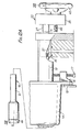
- the injection device 2 includes an atomiser assembly 4 in which the fluid is mechanically atomised during discharge supported in the forward end of the injector barrel 5 which would normally be suitably mounted in the wall of the boiler with its forward end in an operating position inset from the boiler interior.
- a tip valve 6 of the injection device is mounted for axial sliding movement and is acted upon by a spring 7 the bias of which is sufficient to urge the tip valve forwardly to close a discharge passage 8 in the atomiser assembly when there is no fluid supply to the injection device.
- fluid is continuously supplied to the injection device 2 whenever the fluid injector is conditioned to discharge the fluid or is shut-down. It is a particular feature of the injector that when conditioned for non-discharge, fluid is continuously circulated through it to cool the forward region thereof and obviate the need for the injector to be retracted away from the boiler interior. Again, because of the continuous circulation, fuel cracking and blockage in the injector is obviated, and there is no necessity for cleaning between discharge operations.
- a central tube 9 is mounted within the barrel 5 to define an annular duct 10 between itself and the barrel.
- hot fluid under pressure from an external oil fuel delivery line of an oil fuel delivery and return circuit is caused to flow through a central duct within the central tube 9 to and through the tip valve 6 and into a chamber 4a in the atomiser assembly 4 from which the fluid will pass generally radially outwardly to return through the annular duct 10 eventually to return to an external oil fuel return line of the same circuit.
- Such a flow has the result that the tip valve is urged forwardly to close off the discharge passage 8 in the atomiser assembly.
- the chamber 4a is behind the discharge passage and its communication with the central tube and the annular duct is not affected by the closure of the discharge passage so that even though the injection device is conditioned for non-discharge, fluid can continuously circulate within the central tube and barrel 5 past the tip valve, as shown in Figure 2 in which the blocked arrows denote the supply flow and the open arrows the return flow.
- the change-over valve might more aptly be termed a flow reversing or flow diverting valve since its valve spool 47 is, as will be later described, linearJy movable between positions in one of which to divert fluid supplied from the oil supply line along one flow path into the central tube and to provide a return path from the annular duct back to the oil return line, and in the other one of which to divert fluid supplied from the oil supply line along what was the return path into the annular duct and to provide a return path from the central tube (which previously served as said one flow path) back to the oil return line.
- the change-over valve 3 is, like the corresponding component in the fluid injector of our aforementioned patents, operable (in dependence on the position of its valve spool 47) to condition the injector for fluid discharge or non-discharge, that conditioning being directly brought about by a reversible fluid pressure differential the mode of which is determined by the direction of the fluid flow within the injector as controlled by the change-over valve.
- the change-over valve permits a continuous circulation of fluid within the injector from the oil supply back to the oil return line when the injector is coupled into a mains supply of fuel oil.
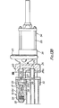
- the present injector of Figures 1 to 7 differs from that of our aforementioned patents in that its change-over valve 3 is not located axially in line with the injector barrel 5. Rather, the change-over valve is displaced downwardly of the barrel, although with its longitudinal axis still parallel with that of the barrel, and there is provided a fluid coupling device 11 between the change-over valve and the rearward end of the barrel.
- the function of the fluid coupling'device 11 is to enable the barrel 5 with the central tube 9 therein to be retracted from the boiler wall to permit inspection, servicing or replacing of the components of the injection device 2 without disturbing the mounting of the change-over valve 3 and the oil supply and return line coupled thereto.
- the fluid coupling device 11 is such that the oil supply and return line are automatically isolated from the unit comprising the injector barrel 5 and the central tube 9 unless the barrel is fully inset to the correct operating position in the boiler wall 15 at which fluid discharge is safely permissible. Retraction of the barrel from the fully inset position automatically causes the fluid coupling device to disconnect the oil supply and return lines from the barrel and central tube unit. Accordingly, even though the change-over valve 3 may be positioned to condition the fluid injector for discharge, until the barrel has been fully inset to the correct operating position discharge will not take place. Indeed, should at that time the change-over valve be positioned to condition the injector for non-discharge but to accept a continuous circulation of fluid through itself, i.e.
- the fluid coupling device will override the change-over valve with respect to permitting flow to the barrel and central tube unit in all positions of the barrel except the fully inset operating one.
- the change-over valve function to cause either discharge from the injector or the injector to have a non-discharge condition with continuous circulation. It follows that if the barrel was accidentally or unintentionally withdrawn with the change-over valve positioned to condition the injector for discharge, the fluid coupling device would function to fail safe the injector. Normally, of course, the change-over valve would be positioned to condition the injector for non-discharge before the barrel was withdrawn.
- a carrier tube 12 which carries at its forward end a flame stabiliser 13.
- the carrier tube is slidably supported in a centre carriage 14 which may form part of a burner plate which, in turn, forms part of the boiler wall 15, or which, as shown, may be a separate component bolted at 16 to the boiler wall.
- the centre carriage is made fast with the boiler wall, and the carrier tube is fixed in any desired position with respect to the boiler wall by means of locating bolts carried by the centre carriage, one such bolt being referenced 17.
- the fully inset position of the barrel at which discharge can be safely permitted is shown in Figures 2 and 4.
- the fluid coupling device 11 comprises a pair of female and male terminals 19 and 20, respectively.
- the female terminal is made fast with the carrier tube 12 and hence is prevented from movement since the carrier tube is fixed to the boiler wall 15.
- the change-over valve 3 is built on to the fixed female terminal.
- the male terminal is made fast with the barrel 5 and hence is movable with it and with respect to the female terminal.
- Carried by each terminal are two valves which are self-actuated to a closure position and which are paired with the corresponding valves of the other terminal such that when the terminals are separated upon the barrel being withdrawn, the valves will automatically move to a closed position with respect to their own terminal.
- the paired valves will automatically urge one another to an open position with respect to their own terminal. It is that closing and opening of the poired valves which isolates and communicates, respectively, the fluid supply and return lines through the change-over valve with respect to the barrel and central tube unit.
- the self-closure valves are denoted by references 21 to 24.
- the male terminal 20 comprises a terminal block 25 which is affixed to the barrel 5 by means of a collar 26a welded thereto and screwed into the block.
- the valves 21, 22 are biased by springs 26 towards their seats 21a, 22a in male collars 27 which are affixed to and project from the terminal block.
- a duct 28 in the terminal block communicates the valve 22 with the barrel annular duct 10, and a second duct 29 in the terminal block connects the other valve 21 with the interior of the central tube 9.
- the female terminal 19 includes a terminal plate 30 to which the housing 31 of the change-over valve 3 is made integral as by bolting at 32.
- a connecting block 33 having fast with its uppeer surface a pair of terminal blocks 34, 34a which have female collars 35 a press fit in the terminal plate.
- the terminal blocks 34, 34a are mounted on opposite sides of the carrier tube 12 and are welded to it by which they together with the terminal plate and the connecting block are made fast with the carrier tube. It is envisaged that the pair of terminal blocks, terminal plate and connecting block could be a one-piece casting.
- the female collars 35 are sized and arranged to receive the respective male collars 27 and make a seal therewith as by scaling rings 36.
- the valves 23, 24 are mounted one in each of the terminal blocks 34, 34a in chambers 37, 37a therein, each of which communicates with the interior of the respective female collar. Springs 38 bias these self-closure valves toward their rrespective seats 23a, 24a in the chambers 37, 37a, the opposite ends of which arc closed by plugs 39.
- a duct 40 extends through the terminal block 3 , the connecting block 35 and the terminal plate 30 to interconnect the chamber 37 with a central chamber 41 in the change-over valve 3.
- a duct 41a extends through the other terminal block 34a, the connecting block and the terminal plate to interconnect the chamber 37a with a radially outer chamber 42 in the change-over valve.
- the male terminal 20 is movable with respect to the fixed female terminal 19 to withdraw and inset the barrel 5 by means of a handwheel 43 which is pinned at 44 to a spindle 45 in turn journalled for rotation in the terminal block 25 but made axially fast therein.
- the forward end 46 of the spindle 45 projects from the terminal block 25 and is screwthreaded to engage in a threaded bore 46a in the terminal plate 30 of the female terminal 19.
- rotation of the handwheel will screw the spindle into or out of the terminal plate and cause the terminal block 25 (together with the barrel and central tube unit) to move towards or away from the terminal plate.
- the terminal block 25 is axially guided during such movement by the sliding engagement of its male collars 27 with the female collars 35 of the terminal blocks 34, 34a.
- an inlet port 48 of the change-over valve which is permanently connected to the oil supply line communicates with the central chamber 41, and an outlet port 49 of the change-over valve which is permanently connected to the oil return line communicates with the radially outer chamber.
- the spool 47 has lands 50, 51 slidable within bushings 52, 53 mounted in the housing 31.
- the central chamber 41 is defined within the bushing 52, and the radially outer chamber 42 between that bushing and the terminal plate 30.
- the spool is selectively linearly movable into fluid discharge and non-discharge positions by any suitable means, that illustrated being a double acting pneumatic piston/cylinder unit 54 whose cylinder is bolted at 55 to the rear end of the bushing 53.
- the flow direction within the fluid injector is such that the injection device will be conditioned for non-discharge whilst at the same time fluid will circulate continuously from the oil supply line through the change-over valve 3 and the interconnected female and male terminals 19, 20 to the central tube 9 and return from the annular duct 20 via those terminals to the change-over valve and thence to the oil return line.
- That direct flow path through the change-over valve enables an additional circulation of fluid to be introduced into the injector in its non-discharge condition, as in the injector of our aforementioned patents.
- An adjustment mechanism is provided whereby dependent on the adjusted position of a back stop cover 64 screwed on to a sleeve 65 projecting rearwardly from an end plate 66 of the air cylinder and within which the valve spool 47 is slidably supported, a back stop 67 attached to the end of the valve spool may be located so that a land 68 on the bushing 53 interferes with fluid flowing from the radial holes 62 in the spool to provide a selective range of fluid flows circulating within the spool which may be preset at any desired fluid flow within the constraints of the geometry of the change-over valve and the energy available for pumping fluid.
- the adjustment mechanism may be omitted so that fluid circulating through the valve spool is fixed for given external pressures operating in the oil supply and return lines.
- the described direct fluid flow path through the change-over valve spool 47 has another purpose, and a particularly important one, in the present injector, as will appear.
- the paired valves 21, 23 and 22, 24 are free to close against their respective seats under the bias of their springs 26 and 38, and so seal off the flow lines in the mule terminal and the female terminal 19.
- fluid is sealed within the barrel and central tube unit.
- the valves in the female terminal seal off the described first and second flow paths therein at the terminal blocks 34, 34a, so that fluid cannot discharge from the female terminal even though the change-over valve 3 continues to communicate the oil supply line therewith.
- the external conduit flow lines coupling the change-over valve 3 with the oil mains line and constituting the oil supply and return lines can be of considerable length.
- fluid can continue to circulate from the oil supply back to the return line directly through the described alternative flow path through the valve spool 47 of the change-over valve, as indicated by the arrows in Figure 5.
- Thu b the oil is kept in a liquid state, and when the barrel 5 is replaced in the carrier tube 12 and inset again to the correct operating position to open again the valve pairs 21, 23 and 22, 24, fluid is able to flow without any appreciable delay from the oil supply line to circulate within the central tube 9 and barrel annular duct 10 back to the return line to cool the injection device 2.
- Fluid can return from the central tube 9 through the duct 29 in the male terminal 20 and via the opened valve pair 21, 23 into the duct 40 in the female terminal 19 to pass downwardly into the central chamber 40 of the change-over valve 3 and through the passage 61 in the spool 47 to flow via the radial holes 62 through the hole 60 in the bushing 53 back into the outlet port 49 to be returned into the oil return line.
- the return flow is denoted by the open arrows in Figures 3 and 4.
- the described flow direction is such as to condition the tip valve 6 to open so that fluid will discharge through the discharge passage 8 as shown in Figure 4.
- the length of the aperture formed between each such valve and its seat must be suitably sized.
- the male terminal 20 is withdrawn together with the barrel and central tube unit by operation of the handwheel 43, fluid flow continues past the valve pairs for part of the travel of the male terminal.
- some tolerance must be provided to accommodate discharge through the injection device 2 in the course of retraction of the barrel, and this tolerance must be provided in defining the allowable position of the injector device in relation to the carrier tube 12 for discharge purposes.
- the fluid injector lA shown therein is generally similar to the injector 1 of Figures 1 to 8 as modified to incorporate the vented male valves 71 and functions in the same way.
- the present injector is modified, to enable the use of a second fluid to regulate discharge.
- attention is drawn to our United Kingdom paten No. 1,497,271 the subject matter of which is incorporated herein by reference.
- the injector lA will only be described herein insofar as the principal differences between it and the injector 1 are concerned.
- the second fluid which could be steam
- a steam supply circuit is connected via an inlet port 75 with the female terminal 19 so that when the two terminals are separated upon withdrawal of the injector device, means must be provided to isolate that steam supply from the broken fluid coupling device 11 so that it cannot escape from the female terminal.
- the steam inlet port 75 is provided in the connecting block 33 and communicates via a duct 76 therein with a chamber 37b in a third terminal block 34b forming a part of the integral block and plate structure of the female terminal 20.
- a third spring biased self closure valve (not shown) is arranged in the chamber 37b to seal against its seat in a female collar when the male terminal 20 is separated from the female terminal.
- a third self venting and fixed male valve 71a is arranged so that its male collar 27 will enter that female collar (in the same manner as the other two male valves in their respective female collars) when the male terminal is connected with the female terminal to open the third spring biased valve to permit steam to escape through that male valve via a duct 77 in a sleeve 78 fast with the terminal block 25 and into the second annular duct 73.
- the fluid injector 18 shown in Figures 12 and 13 is of the pressure jet type which is mechanically atomised and incorporates a fluid atomiser assembly 4A and an operating valve 3A.
- a fluid atomiser assembly 4A and an operating valve 3A.
- either oil fuel is passed down the central tube 9 or the tube and the atomiser assembly is purged with a cooling fluid.
- Cooling fluid is supplied to the operating valve 3A through a port 79 and oil from an oil supply line through a port 80.
- cooling fluid can flow into a chamber 82 in which the spool is reciprocated as by a double acting pneumatic piston/cylinder unit 54 and via a passageway 83 in the spool into a duct 84 in the female terminal and thence into a chamber 37 housing a spring biased closure valve 23. Since the'male terminal is shown withdrawn, the valve 23 is closed to seal off escape of the cooling fluid from that chamber 37.
- the male collar 27 will enter the female collar 35 and cause its self vented and fixed male valve 71 to urge the valve 23 open so that fluid, whether it be oil or purging cooling fluid as the case may be depending on the position of the valve spool 81, is caused to flow from the chamber 37 past the opened valve 23 into the male collar 27 and thence via the duct 29 into the central tube 9 down towards the atomiser assembly 4A.
- Means may be provided for intercommunicating those first and second flow paths to obviate those dead legs upon retraction of the male terminal 20 so that fluid delivered from the oil supply line is able to circulate continuously through them back into the oil return line as well as circulating directly through the valve spool 47 of the change-over valve 3.
- the first and second flow paths are intercommunicated in the female terminal 19 itself when the male terminal 20 is retracted.
- the ducts 40, 41a are interconnected in the female terminal 19 by passages 88, 89 issuing at one end respectively from each and at the opposite end into a valve chamber 90.
- a valve member 91 is biased by a spring 92 off its seat 93 in the valve chamber 90 when the male terminal 20 is retracted so that the passages 88, 89 intercommunicate through the valve chamber.
- valve member 91 extends into a recess 94 in the female terminal 19 with the spring 92 located between the base of the recess and the valve head 95. Sealing means 96 are provided around the stem of the valve member 91 to prevent escape of fluid from the female terminal 19 when the ducts 40, 41a are interconnected.
- the male terminal 20 carries a plug 97 sized to enter the recess 94, when the male terminal 20 is interconnected with the female terminal 19 to inset the barrel 5 at which time it will engage the valve head 95 to urge the valve member 91 against the bias of the spring 92 and into sealing engagement with its valve seat 93 (as shown in Figure 15).
- the passages 88 and 89 are isolated from each other, and the resulting flow paths in the female terminal are as in the first and .second fluid injectors 1 and 1A.
- the bridge 20A is generally similar to the male terminal 20 but lacks the ducts 28 and 29. Instead, a duct 98 in the terminal block 25 direct intercommunicates the valves 21,22. Moreover, the barrel 5 is replaced by a pilot tube 99 closed at its forward end. Whilst the valves 21, 22 are shown as self-actuating to closure they could alternatively be self venting male valves as in Figure 8.
- the male terminal 20 When the male terminal 20 has been retracted to withdraw the barrel to enable inspection or servicing of the injection device 2, it is replaced by the male bridge 20A which couples with the female terminal 19 in the same manner as the male terminal 20.
- the valves 21, 22 engage the valves 23, 24 respectively so that the paired valves open.
- the ducts 40, 41a in the female terminal 19 are connected with each other through the paired opened valves 23, 21,the duct 98 in the male bridge 20A and the paired opened valves 24,22. Accordingly, fluid delivered from the oil supply line to the change-over valve 3 can circulate through the female terminal 19 via the male bridge 20A back into the female terminal to return via the change-over valve into the oil return line.
- the injection device together with the fluid coupling device and flow control valve comprise a composite structure having flow paths internal to that structure (thereby obviating the need for external connecting tubes or pipes between the various components of that structure which could be prone to leakage where connected to the individual components) along which oil can be routed by the flow control valve from the fluid delivery line to the injection device.
- the tip valve embodiments providing for a return flow of oil, such flow will also be routed by the flow control valve back to the fluid return line from the injection device via the fluid coupling device along such internal flow paths.
- An oil burner incorporating any of the fluid injectors as described would also have an air register to provide the combustion air, valves to regulate and shut off the air and fuel supplies and an igniter to initiate combustion.
Landscapes
- Engineering & Computer Science (AREA)
- Chemical & Material Sciences (AREA)
- Combustion & Propulsion (AREA)
- Mechanical Engineering (AREA)
- General Engineering & Computer Science (AREA)
- Feeding And Controlling Fuel (AREA)
- Fuel-Injection Apparatus (AREA)
- Quick-Acting Or Multi-Walled Pipe Joints (AREA)
Abstract
fluid injector 1 for an oil fuel burner suitable for firing the fuel of a boiler includes an injection device 2 which can be inserted into the wall of the boiler to an operating position at which oil discharge can be safely permitted and withdrawn from that operating position for inspection and servicing. A flow control valve 3 of the fluid injector 1 is adapted for connection to an oil fuel and delivery circuit and is mounted in a fixed position relative to the boiler wall. The fluid injector 1 also includes a fluid coupling device 11 between the injection device 2 and the flow control valve 3. The fluid coupling device includes male and female terminals 19 and 20, respectively, which are fast with the injection device 2 and the flow control valve 3, respectively. The male and female terminals 19 and 20 are disconnected as the injection device 2 is withdrawn whilst the change-over valve remains mounted to the boiler wall and connected to the oil fuel and return circuit, at which time the female terminal 20 isolates that circuit from the withdrawn injection device 2 and seals flow from the circuit within itself. When the injection device 2 is inserted to its operating position, the male terminal 19 interconnects with the female terminal 20 to communicate the oil fuel and delivery circuit with the injection device 2 through the flow control valve 3. The flow control valve 3 may provide a direct flow path through itself when the injection device 2 is withdrawn to allow oil to circulate continuously in the oil fuel and delivery circuit at that time.
Description
- This invention concerns improvements in or relating to fluid injectors.
- According to the invention there is provided a fluid injector comprising an injection device, and means for connecting said fluid injector to fluid delivery and return lines, said injection device being capable of being removed from an operating position and relative to said connecting means whilst said connecting means is connected to the fluid delivery and return lines, said fluid injector being such as to provide for flow between the fluid delivery and return lines through said connecting means when said injection device is removed whilst isolating the fluid delivery and return lines from said injection device upon such removal.
- The invention may be applied to various fluid injectors. One such injector has a tip shut off facility and is mechanically atomised and has a change-over valve which connects to a fluid delivery and return circuit as featured in our United Kingdom patents Nos. 1,233,317 and 1,231,631.
- Another fluid injector to which the invention may be applied is one of the pressure jet type which is mechanically atomised and incorporates a fluid atomiser at the discharge end and an operating valve which connects to a fluid delivery and return circuit.
- A third fluid injector is a multi-fluid injector with a tip shut off facility which is atomised by a second fluid and includes a means to select discharge of either fluid or a mixture of the fluids and includes a change-over valve which connects to a fluid delivery and return circuit. Such an injector is featured in our United Kingdom patent No. 1,497,271.
- In a fluid injector constructed in accordance with one preferred embodiment of the invention, interlocking male and female terminals are arranged so that it is not possible to condition the injector for discharge until the tip valve or the fluid atomiser whichever the case may be has been inset to the position at which discharge can be safely permitted. Conversely, the interlocking device is arranged so that the tip valve or fluid atomiser may not be retracted from the position of proper discharge without first isolating the fluid supply. In these fluid injectors which utilize a second fluid such as the pressure jet type which although mechanically atomised is both purged and cooled by a second fluid and the multi-fluid injector having a tip shut off facility which relies on a second fluid to assist atomisation as well as for purging and cooling, then the second fluid is also ported through the interlocking device so that upon retraction of the tip valve or fluid atomiser the supply of second fluid is also isolated.
- In circumstances whereby the tip valve or fluid atomiser may be accidentally or unintentionally retracted with the change-over valve or operating valve positioned to condition the tip valve or fluid atomiser for fluid discharge, the interlocking device will operate to isolate the fluid delivery and return circuit as well as the second fluid circuit before the tip valve or fluid atomiser is retracted from the range of positions at which discharge can be permitted.
- External means may be provided so that in the event the tip valve or fluid atomiser is accidentally retracted when conditioned to discharge, then the change-over valve or operating valve may be automatically positioned as if to condition the injector for non-discharge.
- In order that the invention may be well understood there will now be described some preferred embodiments thereof, given by way of example, reference being had to the accompanying drawings, in which:
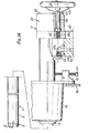
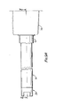
- Figures 1A and 1B together comprise a side elevation, partly sectioned, of a first fluid injector in an inset operating position but conditioned for non-discharge;
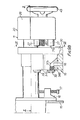
- Figures 2A and 2B together comprise a sectioned plan view along line II-II of Figure 1;
- Figure 3 is a view corresponding to Figures 1A and 1B showing the same fluid injector not only in an inset operating position but also conditioned for discharge;
- Figure 4 is a scrap plan view sectioned along line IV-IV of Figure 3;
- Figure 5 is a view corresponding to Figures 1A and 1B but showing the same fluid injector in a non-operating position;
- Figure 6 is a scrap plan view sectioned along line VI-VI of Figure 5;
- Figure 7 is an end view taken on line VIII-VIII of Figure 1 but with the change-over valve of the fluid injector removed;
- Figure 8 is a scrap sectioned plan view of a similar injector to that shown in the preceding figures but with an alternative mechanical interlocking terminal;
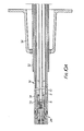
- Figures 9A, 9B and 9C together comprise a side elevation, partly sectioned, of a second fluid injector in a non-operating position;
- Figures 10A and 10B together comprise a sectioned plan view along line X-X of Figure 9) ;
- Figure 11 is an end view taken on line XI-XI of Figure 9 but with the change-over valve of the fluid injector removed;
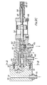
- Figures 12A and 12B together comprise a side elevation, partly sectioned, of a third fluid injector in a non-operating position;
- Figures 13A and 13B together comprise a sectioned plan view along line XIII-XIII of Figure 12;
- Figure 14 is a part sectioned plan view showing modified male and female terminals for each of the first and second fluid injectors when the injector is in a non-operating position;
- Figure 15 is a scrap view corresponding to Figure 15 but showing the male and female terminals interconnected; and
- Figure 16 is a scrap sectioned plan view showing a male bridge mated with the female terminal of the first or second fluid injector.
- In the various figures, like references indicate like parts.
- Each of the fluid injectors to be described is primarily intended for incorporation in an oil fuel burner suitable for use in a fossil fired burner. Such burners are arranged in the furnace walls of the boiler for firing the boiler's fuel. Oil fuel is used as the prime fuel for firing burners, or as a secondary fuel for igniting coal when that is the primary fuel, or in combination with gas as an alternative primary fuel. The boiler would generate steam, and have land, marine or other industrial applications.
- The fluid injector 1 shown in Figures 1 to 7 has a considerable degree of similarity to that disclosed in our United Kingdom patents Nos. 1,231,631 and 1,233,317 in that it includes an
injection device 2 at its forward end and a change-overvalve 3 at its rearward end, both of which are essentially constructed and operate in a like manner to their counterparts in those patents. As such, the injection device and change-over valve will only be described herein so far as it may be necessary for the present injector to be understood, and attention is directed to our aforementioned patents for a full and complete disclosure which is herein incorporated by reference. - Thus, the
injection device 2 includes an atomiser assembly 4 in which the fluid is mechanically atomised during discharge supported in the forward end of theinjector barrel 5 which would normally be suitably mounted in the wall of the boiler with its forward end in an operating position inset from the boiler interior. A tip valve 6 of the injection device is mounted for axial sliding movement and is acted upon by aspring 7 the bias of which is sufficient to urge the tip valve forwardly to close a discharge passage 8 in the atomiser assembly when there is no fluid supply to the injection device. - Normally, fluid is continuously supplied to the
injection device 2 whenever the fluid injector is conditioned to discharge the fluid or is shut-down. It is a particular feature of the injector that when conditioned for non-discharge, fluid is continuously circulated through it to cool the forward region thereof and obviate the need for the injector to be retracted away from the boiler interior. Again, because of the continuous circulation, fuel cracking and blockage in the injector is obviated, and there is no necessity for cleaning between discharge operations. - When fluid is supplied to the
injection device 2, the position of the tip valve 6 is hydraulically controlled by a pressure differential derived from the supply flow to, and return flow from, the tip valve in conjunction with the relative areas thereof acted upon by such flows. For that purpose, acentral tube 9 is mounted within thebarrel 5 to define anannular duct 10 between itself and the barrel. - In a non-discharge condition of the
injection device 2, hot fluid under pressure from an external oil fuel delivery line of an oil fuel delivery and return circuit is caused to flow through a central duct within thecentral tube 9 to and through the tip valve 6 and into a chamber 4a in the atomiser assembly 4 from which the fluid will pass generally radially outwardly to return through theannular duct 10 eventually to return to an external oil fuel return line of the same circuit. Such a flow has the result that the tip valve is urged forwardly to close off the discharge passage 8 in the atomiser assembly. The chamber 4a is behind the discharge passage and its communication with the central tube and the annular duct is not affected by the closure of the discharge passage so that even though the injection device is conditioned for non-discharge, fluid can continuously circulate within the central tube andbarrel 5 past the tip valve, as shown in Figure 2 in which the blocked arrows denote the supply flow and the open arrows the return flow. - In a discharge condition of the
injection device 2, the direction of fluid flow just described is reversed, as shown in Figure 4, so that the supply flow is along theannular duct 10 to the injection device and the return flow from the injection device is through thecentral tube 9. The reversed flow results in the tip valve 6 being urged rearwardly to open the discharge passage 8 and so effect fluid discharge therethrough, as illustrated. - The reversal of fluid flow within the
central tube 9 and theannular duct 10 within thebarrel 5 to bring about the discharge and non-discharge conditions of theinjection device 2 is under the control of the change-overvalve 3. The change-over valve might more aptly be termed a flow reversing or flow diverting valve since itsvalve spool 47 is, as will be later described, linearJy movable between positions in one of which to divert fluid supplied from the oil supply line along one flow path into the central tube and to provide a return path from the annular duct back to the oil return line, and in the other one of which to divert fluid supplied from the oil supply line along what was the return path into the annular duct and to provide a return path from the central tube (which previously served as said one flow path) back to the oil return line. - From the above, it will be seen that the change-over
valve 3 is, like the corresponding component in the fluid injector of our aforementioned patents, operable (in dependence on the position of its valve spool 47) to condition the injector for fluid discharge or non-discharge, that conditioning being directly brought about by a reversible fluid pressure differential the mode of which is determined by the direction of the fluid flow within the injector as controlled by the change-over valve. Moreover, when conditioning the fluid injector for non-discharge, the change-over valve permits a continuous circulation of fluid within the injector from the oil supply back to the oil return line when the injector is coupled into a mains supply of fuel oil. - The present injector of Figures 1 to 7 differs from that of our aforementioned patents in that its change-over
valve 3 is not located axially in line with theinjector barrel 5. Rather, the change-over valve is displaced downwardly of the barrel, although with its longitudinal axis still parallel with that of the barrel, and there is provided afluid coupling device 11 between the change-over valve and the rearward end of the barrel. - The function of the
fluid coupling'device 11 is to enable thebarrel 5 with thecentral tube 9 therein to be retracted from the boiler wall to permit inspection, servicing or replacing of the components of theinjection device 2 without disturbing the mounting of the change-overvalve 3 and the oil supply and return line coupled thereto. - The
fluid coupling device 11 is such that the oil supply and return line are automatically isolated from the unit comprising theinjector barrel 5 and thecentral tube 9 unless the barrel is fully inset to the correct operating position in theboiler wall 15 at which fluid discharge is safely permissible. Retraction of the barrel from the fully inset position automatically causes the fluid coupling device to disconnect the oil supply and return lines from the barrel and central tube unit. Accordingly, even though the change-overvalve 3 may be positioned to condition the fluid injector for discharge, until the barrel has been fully inset to the correct operating position discharge will not take place. Indeed, should at that time the change-over valve be positioned to condition the injector for non-discharge but to accept a continuous circulation of fluid through itself, i.e. through the central tube and theannular duct 10 in the barrel, the continuous circulation will not take place either. In other words, the fluid coupling device will override the change-over valve with respect to permitting flow to the barrel and central tube unit in all positions of the barrel except the fully inset operating one. When, and only when, the barrel is in that position can the change-over valve function to cause either discharge from the injector or the injector to have a non-discharge condition with continuous circulation. It follows that if the barrel was accidentally or unintentionally withdrawn with the change-over valve positioned to condition the injector for discharge, the fluid coupling device would function to fail safe the injector. Normally, of course, the change-over valve would be positioned to condition the injector for non-discharge before the barrel was withdrawn. It should be mentioned that there is some degrec of latitude available in that there is a limited range of positions of the barrel at which fluid discharge can be safely permitted, and the fluid coupling device will not function to isolate the fluid supply and return lines until the rearward limit of that positional range is rcached. - Describing now themounting of the
barrel 5, it is housed in acarrier tube 12 which carries at its forward end aflame stabiliser 13. The carrier tube is slidably supported in acentre carriage 14 which may form part of a burner plate which, in turn, forms part of theboiler wall 15, or which, as shown, may be a separate component bolted at 16 to the boiler wall. In any event, the centre carriage is made fast with the boiler wall, and the carrier tube is fixed in any desired position with respect to the boiler wall by means of locating bolts carried by the centre carriage, one such bolt being referenced 17. The fully inset position of the barrel at which discharge can be safely permitted is shown in Figures 2 and 4. - The
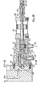
fluid coupling device 11 comprises a pair of female andmale terminals carrier tube 12 and hence is prevented from movement since the carrier tube is fixed to theboiler wall 15. The change-overvalve 3 is built on to the fixed female terminal. The male terminal is made fast with thebarrel 5 and hence is movable with it and with respect to the female terminal. Carried by each terminal are two valves which are self-actuated to a closure position and which are paired with the corresponding valves of the other terminal such that when the terminals are separated upon the barrel being withdrawn, the valves will automatically move to a closed position with respect to their own terminal. Conversely, when the barrel is fully inset and the terminals are engaged with one another, the paired valves will automatically urge one another to an open position with respect to their own terminal. It is that closing and opening of the poired valves which isolates and communicates, respectively, the fluid supply and return lines through the change-over valve with respect to the barrel and central tube unit. The self-closure valves are denoted byreferences 21 to 24. - The
male terminal 20 comprises aterminal block 25 which is affixed to thebarrel 5 by means of acollar 26a welded thereto and screwed into the block. Thevalves springs 26 towards theirseats male collars 27 which are affixed to and project from the terminal block. Aduct 28 in the terminal block communicates thevalve 22 with the barrelannular duct 10, and asecond duct 29 in the terminal block connects theother valve 21 with the interior of thecentral tube 9. - The
female terminal 19 includes aterminal plate 30 to which thehousing 31 of the change-overvalve 3 is made integral as by bolting at 32. Suitably made fast with the terminal plate is a connectingblock 33 having fast with its uppeer surface a pair of terminal blocks 34, 34a which have female collars 35 a press fit in the terminal plate. The terminal blocks 34, 34a are mounted on opposite sides of thecarrier tube 12 and are welded to it by which they together with the terminal plate and the connecting block are made fast with the carrier tube. It is envisaged that the pair of terminal blocks, terminal plate and connecting block could be a one-piece casting. - The
female collars 35 are sized and arranged to receive the respectivemale collars 27 and make a seal therewith as by scalingrings 36. Thevalves chambers Springs 38 bias these self-closure valves toward theirrrespective seats chambers - A
duct 40 extends through theterminal block 3 , the connectingblock 35 and theterminal plate 30 to interconnect thechamber 37 with acentral chamber 41 in the change-overvalve 3. Aduct 41a extends through the otherterminal block 34a, the connecting block and the terminal plate to interconnect thechamber 37a with a radiallyouter chamber 42 in the change-over valve. - The
male terminal 20 is movable with respect to the fixedfemale terminal 19 to withdraw and inset thebarrel 5 by means of ahandwheel 43 which is pinned at 44 to aspindle 45 in turn journalled for rotation in theterminal block 25 but made axially fast therein. Theforward end 46 of thespindle 45 projects from theterminal block 25 and is screwthreaded to engage in a threadedbore 46a in theterminal plate 30 of thefemale terminal 19. Thus, rotation of the handwheel will screw the spindle into or out of the terminal plate and cause the terminal block 25 (together with the barrel and central tube unit) to move towards or away from the terminal plate. Theterminal block 25 is axially guided during such movement by the sliding engagement of itsmale collars 27 with thefemale collars 35 of the terminal blocks 34, 34a. - When the
barrel 5 is fully inset in theboiler wall 15 and hence is positioned as shown in Figure 2, themale collars 27 are fully engaged in thefemale collars 35. In moving to that position, the pairedvalves respective springs respective seats central chamber 41 in the change-overvalve 3 comprising theduct 40 and thechamber 37 is communicated through the pairedopen valves duct 29 in themale terminal 20 and hence with thecentral tube 9. At the same time, a second flow path in the female terminal from the radiallyouter chamber 42 of the change-over valve comprising theduct 41a and thechamber 37a is communicated through the pairedopen valves duct 28 in the male terminal and hence with theannular duct 10 in thebarrel 5. - When the
spool 47 of the change-overvalve 3 is positioned as shown in Figure 1, aninlet port 48 of the change-over valve which is permanently connected to the oil supply line communicates with thecentral chamber 41, and anoutlet port 49 of the change-over valve which is permanently connected to the oil return line communicates with the radially outer chamber. - Detailing more the structure of the change-over
valve 3, thespool 47 haslands bushings housing 31. Thecentral chamber 41 is defined within thebushing 52, and the radiallyouter chamber 42 between that bushing and theterminal plate 30. The spool is selectively linearly movable into fluid discharge and non-discharge positions by any suitable means, that illustrated being a double acting pneumatic piston/cylinder unit 54 whose cylinder is bolted at 55 to the rear end of thebushing 53. - Thereby, the positioning of
the'valve spool 47 shown in Figure 1 will cause, when theterminals inlet port 48 and aradial hole 56 in thebushing 52 into thecentral chamber 41. From there, the fluid flows through the first flow path in the female terminal to and through the openedvalve pair duct 29 in the male terminal and finally into thecentral tube 9, as indicated by the blocked arrows in Figures 1 and 2. At the same time, fluid can return through the barrelannular duct 20 via theduct 28 in the male terminal and the openedvalve pair outer chamber 42 of the change-over valve. From there, the return fluid will flow through anaxially extending passage 57 in thebushing 52 into achamber 58 between the bushings and along apassage 59 between thebushing 53 and the valve spool to exit ahead of theland 51 via aradial hole 60 in the same bushing into theoutlet port 49 to return to the oil return line. The return flow is denoted by the open arrows in Figures 1 and 2. - Accordingly, the flow direction within the fluid injector is such that the injection device will be conditioned for non-discharge whilst at the same time fluid will circulate continuously from the oil supply line through the change-over
valve 3 and the interconnected female andmale terminals central tube 9 and return from theannular duct 20 via those terminals to the change-over valve and thence to the oil return line. - At the same time, an alternative flow path is provided from the oil supply to the return line directly through the
valve spool 47 of the change-overvalve 3 by means of theinlet port 48,hole 56,central chamber 41, anaxial passage 61 andradial holes 62 in the spool, andradial holes 63 in thebushing 53 which communicate with theoutlet port 49, as indicated by the open arrows in Figure 1. - That direct flow path through the change-over valve enables an additional circulation of fluid to be introduced into the injector in its non-discharge condition, as in the injector of our aforementioned patents.
- An adjustment mechanism is provided whereby dependent on the adjusted position of a
back stop cover 64 screwed on to asleeve 65 projecting rearwardly from anend plate 66 of the air cylinder and within which thevalve spool 47 is slidably supported, aback stop 67 attached to the end of the valve spool may be located so that aland 68 on thebushing 53 interferes with fluid flowing from the radial holes 62 in the spool to provide a selective range of fluid flows circulating within the spool which may be preset at any desired fluid flow within the constraints of the geometry of the change-over valve and the energy available for pumping fluid. Alternatively, the adjustment mechanism may be omitted so that fluid circulating through the valve spool is fixed for given external pressures operating in the oil supply and return lines. - The described direct fluid flow path through the change-over
valve spool 47 has another purpose, and a particularly important one, in the present injector, as will appear. - When it is wished to inspect or service the
injection device 2, thehandwheel 43 is rotated to urge themale terminal 20 rearwardly and so withdraw thebarrel 5 inside thecarrier tube 12. The new position of the then "broken"fluid coupling device 11 is as shown in Figures 5 and 6 with the change-overvalve 3 remaining, of course, in the same non-discharge position as before. - When the
male terminal 20 is so withdrawn, the pairedvalves springs female terminal 19. Thus, fluid is sealed within the barrel and central tube unit. More importantly, the valves in the female terminal seal off the described first and second flow paths therein at the terminal blocks 34, 34a, so that fluid cannot discharge from the female terminal even though the change-overvalve 3 continues to communicate the oil supply line therewith. - The external conduit flow lines coupling the change-over
valve 3 with the oil mains line and constituting the oil supply and return lines can be of considerable length. When themale terminal 20 is retracted, fluid can continue to circulate from the oil supply back to the return line directly through the described alternative flow path through thevalve spool 47 of the change-over valve, as indicated by the arrows in Figure 5. Thub, the oil is kept in a liquid state, and when thebarrel 5 is replaced in thecarrier tube 12 and inset again to the correct operating position to open again the valve pairs 21, 23 and 22, 24, fluid is able to flow without any appreciable delay from the oil supply line to circulate within thecentral tube 9 and barrelannular duct 10 back to the return line to cool theinjection device 2. - There are short dead legs of fluid within the first and second flow paths in the
female terminal 19 when themale terminal 20 is retracted, but these are kept liquid by heat conduction through contact with the heated oil circulating directly through the change-over valve. - The direct flow path through the change-over valve from the oil supply to the return line when the change-over valve is conditioning the injector for non-discharge is present, as said, in the injector of our aforementioned patents, but only for the purpose of enabling additional fluid to be circulated within the injector. Since the change-over valve was built in to the rear end of the barrel, it had to be withdrawn with the barrel, and the supply flow needed to be shut off at that time. Accordingly, there was no reason to suppose that the direct fluid flow path could serve the present purpose, and it was only when we introduced the
fluid coupling device 11 into the injector that we realised, unexpectedly, the extra function which that flow path could serve and the beneficial effect which resulted. - Without that direct flow path, there could exist dead legs of oil within the lengthy conduits of the oil supply and return lines which would tend to solidify depending on the "down time" of the injector for maintenance and which would take some time after inset of the barrel to liquefy during which time the injector device, in being starved of circulating fluid, could become overheated and damaged.
- When the
barrel 5 is fully inset in theboiler wall 15 and the injector is to be conditioned for fluid discharge, the change-overvalve spool 47 is moved to the position shown in Figure 3. Thereby, fluid will flow from the oil supply line through theinlet port 48 of the change-over valve and via theradial hole 56 into apassage 68 behind thespool land 50 and thence through thechamber 58 in the reverse direction through thepassage 57 to emerge in the radiallyouter chamber 42. From there, the fluid flows upwardly in the duct 4la in thefemale terminal 19 to pass via the openedvalve pair duct 28 of themale terminal 20 and thence into the barrelannular duct 10. The supply flow of fluid is indicated by the solid arrows in Figures 3 and 4. - Fluid can return from the
central tube 9 through theduct 29 in themale terminal 20 and via the openedvalve pair duct 40 in thefemale terminal 19 to pass downwardly into thecentral chamber 40 of the change-overvalve 3 and through thepassage 61 in thespool 47 to flow via the radial holes 62 through thehole 60 in thebushing 53 back into theoutlet port 49 to be returned into the oil return line. The return flow is denoted by the open arrows in Figures 3 and 4. - The described flow direction is such as to condition the tip valve 6 to open so that fluid will discharge through the discharge passage 8 as shown in Figure 4.
- As described, there is a spill back of fluid from the
injection device 2 along thecentral tube 9 in that not all the fluid which is supplied to the injection device is discharged. An additional adjustment is provided whereby dependent upon the position ofadjustment nuts 69 on the rear end of thevalve spool 47, a land 70 on thebushing 53 is allowed to interfere with fluid spilling back from the radial holes 62 via thebushing hole 60 into theoutlet port 49, with the result that the proportion of fluid which is returned to the oil return line may be selectively adjusted to zero to provide a range of discharge flowf for given external pressures operating in the fluid deliver and return lines. Alternatively, the adjustment nuts may be omitted so that fluid discharge from the injector is fixed for such given external pressures. - To permit an adequate fluid flow through the opened valve pairs 21, 23 and 22, 24 when the male 20 and female 19 terminals are engaged, the length of the aperture formed between each such valve and its seat must be suitably sized. In consequence, when the
male terminal 20 is withdrawn together with the barrel and central tube unit by operation of thehandwheel 43, fluid flow continues past the valve pairs for part of the travel of the male terminal. Thus, some tolerance must be provided to accommodate discharge through theinjection device 2 in the course of retraction of the barrel, and this tolerance must be provided in defining the allowable position of the injector device in relation to thecarrier tube 12 for discharge purposes. Additional tolerance must be provided so that as the barrel is withdrawn and the male terminal slidingly disengages from the female terminal, then for that length of travel of the male terminal that fluid flow past the valve pairs continues, themale collars 27 must be sealed within thefemale collars 35 as is achieved by theseals 36. - With the self actuating to
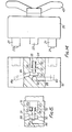
closure valves male terminal 20 in the above described injector, no means is provided for relieving the pressure or venting the fluid within the injector barrel when withdrawn. Such means is provided in the alternative male terminal 20 shown in Figure 8 which shows, instead of spring biased valves self actuated to closure, self vented and fixedmale valves 71 providing axial fluid flow holes 72 to the interior of themale collars 27 which serve the same purpose as the self actuated valves. - Referring now to Figures 9 to 11, the fluid injector lA shown therein is generally similar to the injector 1 of Figures 1 to 8 as modified to incorporate the vented
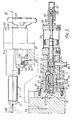
male valves 71 and functions in the same way. The present injector, is modified, to enable the use of a second fluid to regulate discharge. For a full disclosure of theinjector device 2A and the change-overvalve 3 of the injector lA, attention is drawn to our United Kingdom paten No. 1,497,271 the subject matter of which is incorporated herein by reference. - The injector lA will only be described herein insofar as the principal differences between it and the injector 1 are concerned. Thus the second fluid, which could be steam, is supplied to the
injector device 2A along anannular duct 73 defined between thebarrel 5 and an encompassingouter tube 74 which is made fast with the barrel and central tube unit and which is also made fast with themale terminal 20. A steam supply circuit is connected via aninlet port 75 with thefemale terminal 19 so that when the two terminals are separated upon withdrawal of the injector device, means must be provided to isolate that steam supply from the brokenfluid coupling device 11 so that it cannot escape from the female terminal. - To that end, the
steam inlet port 75 is provided in the connectingblock 33 and communicates via aduct 76 therein with achamber 37b in a third terminal block 34b forming a part of the integral block and plate structure of thefemale terminal 20. A third spring biased self closure valve (not shown) is arranged in thechamber 37b to seal against its seat in a female collar when themale terminal 20 is separated from the female terminal. A third self venting and fixedmale valve 71a is arranged so that itsmale collar 27 will enter that female collar (in the same manner as the other two male valves in their respective female collars) when the male terminal is connected with the female terminal to open the third spring biased valve to permit steam to escape through that male valve via a duct 77 in asleeve 78 fast with theterminal block 25 and into the secondannular duct 73. - The fluid injector 18 shown in Figures 12 and 13 is of the pressure jet type which is mechanically atomised and incorporates a
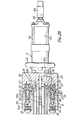
fluid atomiser assembly 4A and anoperating valve 3A. In this embodiment, either oil fuel is passed down thecentral tube 9 or the tube and the atomiser assembly is purged with a cooling fluid. There is no return path from the atomiser assembly and hence only one set of valve means sealing the supplied fluid within thefemale terminal 19 when themale terminal 20 is withdrawn to retract the atomiser assembly is necessary. - Cooling fluid is supplied to the
operating valve 3A through aport 79 and oil from an oil supply line through aport 80. In the position of thespool 81 of the operating valve shown in Figure 12, cooling fluid can flow into achamber 82 in which the spool is reciprocated as by a double acting pneumatic piston/cylinder unit 54 and via apassageway 83 in the spool into aduct 84 in the female terminal and thence into achamber 37 housing a springbiased closure valve 23. Since the'male terminal is shown withdrawn, thevalve 23 is closed to seal off escape of the cooling fluid from thatchamber 37. In the same position of the valve spool, there is a direct flow path from the oil supply line to the oil return line via theport 80 andpassageways 85 through thebushing 86 and around the spool into anoil outlet port 87. Hence oil can circulate continuously between the lines and so not be prone to solidifying. When the spool is retracted, oil can flow from theport 80 into theduct 84 but again is prevented by the closed valve from escaping from the female terminal. - When the
handwheel 43 is rotated to screw its threadedspindle end 46 into theterminal plate 30 and so inset theatomiser assembly 44 into the boiler wall, themale collar 27 will enter thefemale collar 35 and cause its self vented and fixedmale valve 71 to urge thevalve 23 open so that fluid, whether it be oil or purging cooling fluid as the case may be depending on the position of thevalve spool 81, is caused to flow from thechamber 37 past the openedvalve 23 into themale collar 27 and thence via theduct 29 into thecentral tube 9 down towards theatomiser assembly 4A. - As mentioned,when the
male terminal 20 is retracted there are short dead legs of fluid within the first and second flow paths in thefemale terminal 19 of the first andsecond fluid injectors 1 and 1A. Means may be provided for intercommunicating those first and second flow paths to obviate those dead legs upon retraction of themale terminal 20 so that fluid delivered from the oil supply line is able to circulate continuously through them back into the oil return line as well as circulating directly through thevalve spool 47 of the change-overvalve 3. - In one such arrangement shown in Figures 14 and 15, the first and second flow paths are intercommunicated in the
female terminal 19 itself when themale terminal 20 is retracted. Thus, as shown in Figure 14, theducts female terminal 19 bypassages valve chamber 90. , Avalve member 91 is biased by aspring 92 off itsseat 93 in thevalve chamber 90 when themale terminal 20 is retracted so that thepassages valve 3 and thence along theduct 40,passage 88,valve chamber 90,passage 89 andduct 41a back into the change-over valve to exit into the oil return line. Thevalve member 91 extends into arecess 94 in thefemale terminal 19 with thespring 92 located between the base of the recess and thevalve head 95. Sealing means 96 are provided around the stem of thevalve member 91 to prevent escape of fluid from thefemale terminal 19 when theducts plug 97 sized to enter therecess 94, when themale terminal 20 is interconnected with thefemale terminal 19 to inset thebarrel 5 at which time it will engage thevalve head 95 to urge thevalve member 91 against the bias of thespring 92 and into sealing engagement with its valve seat 93 (as shown in Figure 15). Thereby, thepassages second fluid injectors 1 and 1A. - In an alternative arrangement shown in Figure 16 for intercommunicating the first and second flow paths in the
female terminal 19 when themale terminal 20 is retracted, the interconnection is through a male terminal in the form of abridge 20A. - The
bridge 20A is generally similar to themale terminal 20 but lacks theducts duct 98 in theterminal block 25 direct intercommunicates thevalves barrel 5 is replaced by apilot tube 99 closed at its forward end. Whilst thevalves - When the
male terminal 20 has been retracted to withdraw the barrel to enable inspection or servicing of theinjection device 2, it is replaced by themale bridge 20A which couples with thefemale terminal 19 in the same manner as themale terminal 20. When so coupled, thevalves valves ducts female terminal 19 are connected with each other through the paired openedvalves duct 98 in themale bridge 20A and the paired openedvalves valve 3 can circulate through thefemale terminal 19 via themale bridge 20A back into the female terminal to return via the change-over valve into the oil return line. - It will be noted that in each of the fluid injectors as disclosed herein, when the male and female terminals are interconnected, the injection device together with the fluid coupling device and flow control valve comprise a composite structure having flow paths internal to that structure (thereby obviating the need for external connecting tubes or pipes between the various components of that structure which could be prone to leakage where connected to the individual components) along which oil can be routed by the flow control valve from the fluid delivery line to the injection device. Moreover, in the case of the tip valve embodiments providing for a return flow of oil, such flow will also be routed by the flow control valve back to the fluid return line from the injection device via the fluid coupling device along such internal flow paths.
- An oil burner incorporating any of the fluid injectors as described would also have an air register to provide the combustion air, valves to regulate and shut off the air and fuel supplies and an igniter to initiate combustion.
Claims (40)
1. A fluid injector comprising an injection device, and means for connecting said fluid injector to fluid delivery and return lines, said injection device being capable of being removed from an operating position and relative to said connecting means whilst said connecting means is connected to the fluid delivery and return lines, said fluid injector being such as to provide for flow between the fluid delivery and return lines through said connecting means when said injection device is removed whilst isolating the fluid delivery and return lines from said injection device upon such removal.
2. A fluid injector as claimed in claim 1, wherein the act of removal of said injection device automatically isolates the fluid delivery and return lines from said injection device, and wherein the act of replacement of said injection device to its said operating position can serve automatically to communicate said fluid delivery and return lines to said injection device.
3. A fluid injector as claimed in claim 2, including a flow control valve having inlet and return ports which comprise said means for connecting said fluid injector to the fluid delivery and return lines, respectively, said flow control valve being movable between positions to condition said fluid injector for discharge or non-discharge when said injection device is in its said operating position.
4. A fluid injector as claimed in claim 3, wherein said flow control valve provides a direct flow path through itself interconnecting said inlet and return ports at least when conditioning said injection device for non-discharge, by which to provide for said flow between the fluid delivery and return lines when said injection device is removed.
5. A fluid injector as claimed in claim 4, including a fluid coupling device between said flow control valve and said injector device which automatically isolates the fluid delivery and return lines from said injection device upon said act of removal of said injection device and which automatically communicates the fluid delivery and return lines with said injection device upon said act of replacement of said injection device providing that said flow control valve'is in its position at which to condition said fluid injector for discharge.
6. A fluid injector as claimed in claim 5, wherein said fluid coupling device includes male and female terminals one of which is associated with said injection device and the other of which is associated with said flow control valve such that said terminals are interconnected to permit fluid flow between themselves when said injection device is in its said operating position and such that said terminals are disconnected from each other when said injector device is removed at which time said other terminal automatically isolates the fluid delivery and return lines from said injector device.
7. A fluid injector as claimed in claim 6, wherein said male terminal is associated with said injection device, and wherein said female terminal is associated with said flow control valve.
8. A fluid injector as claimed in claim 6 or claim 7, wherein said one terminal includes first flow path means communicating with said injection device, said other terminal includes second flow path means communicating with said flow control valve, and at least said other terminal includes valve means self-actuated to closure to seal off said second flow path means at which time the fluid delivery and return lines are isolated from said injection device, said valve means being urged open by said one terminal when said terminals are interconnected to permit flow between said first and second flow path means, and said valve means automatically moving to closure when said terminals are disconnected.
9. A fluid injector as claimed in claim 8, wherein " said one terminal includes valve means self-actuated to closure to seal off said first flow path means, said pair of valve means urging each other open when said terminals are interconnected to communicate said first and second flow path means with each other, and each of said pair of valve means automatically moving to closure upon disconnection of said terminals.
10. A fluid injector as claimed in claim 8, wherein said one terminal includes fixed valve means in said first flow path means and formed to permit fluid flow therepast when said terminals are interconnected and to vent said injection device when said terminals are disconnected.
11. A fluid injector as claimed in claim 9 or claim 10, wherein said injection device includes a discharge passage and a tip valve for controlling discharge through said discharge passage, said flow control valve being movable into one position to condition said tip valve to permit fluid discharge through said discharge passage and into another position to condition said tip valve to close said discharge passage at which time said injection device will accept a continuous circulation of fluid through itself.
12. A fluid injector as claimed in claim 11, wherein said flow control valve in being moved between its said positions changes within said fluid injector the direction of flow of fluid supplied thereto from said fluid delivery line, said conditioning of said tip valve being directly brought about by a reversible fluid pressure differential within said injector device the mode of which is determined by the direction of the fluid flow as controlled by said flow control valve.
13. A fluid injector as claimed in claim 11 or claim 12, wherein said first flow path means comprises first and second flow paths communicating with first and second ducts respectively in said injection device, said valve means of said one terminal comprises a pair of valves one in each of said first and second flow paths, said second flow path means comprises further first and second flow paths, said valve means of said other terminal comprises a pair of valves one in each of said first and second flow paths thereof, said first and second flow paths of said other terminal being matched with said first and second flow paths of said one terminal so that the valves thereof are paired with each other, said flow control valve in one of its said positions causing fluid to flow from the fluid delivery line through said matched first flow paths into said first duct to return via said second duct and said matched second flow paths into the fluid return line, said flow control valve in the other of its said positions causing fluid to flow from the fluid delivery line through said matched second flow paths into said second duct to return via said first duct and said matched first flow paths into the fluid return line.
14. A fluid injector as claimed in claim 13, wherein said flow control valve is movable into a range of fluid discharge positions in which to provide a return path from the respective flow path to the fluid return line by which, in dependence on the particular position of said flow control valve, greater or lesser return flows can be obtained and hence a variable discharge flow through said discharge passage for a particular fluid supply pressure in said fluid supply line.
15. A fluid injector as claimed in claim 14, wherein said fluid discharge valve is movable into a fluid discharge position in which to prevent flow back into the fluid return line.
16. A fluid injector as claimed in any of claims 13 to 15, including means for intercommunicating said first and second flow paths of said other terminal when said terminals are disconnected from each other, by which fluid delivered from said fluid delivery line may circulate continuously through those first and second flow paths to return into the fluid return line.
17. A fluid injector as claimed in claim 16, wherein said intercommunicating means function automatically to intercommunicate said first and second flow paths of said other terminal upon the act of disconnection of said terminals.
18. A fluid injector as claimed in claim 17, wherein said intercommunicating means comprise first and second passages in said other terminal communicating respectively with said first and second flow paths thereof and valve means self-actuating to an open position to intercommunicate said first and second passages when said terminals are disconnected from each other, interconnection of said terminals automatically moving the same valve means to closure to isolate said first and second passages from each other.
19. A fluid injector as claimed in claim 16, wherein said intercommunicating means comprises a terminal bridge adapted to connect with said other terminal upon removal of said one terminal and when so connected to open said pair of valves of said other terminal and provide a duct through itself directly intercommunicating said first and second flow paths of said other terminal.
20. A fluid injector as claimed in claim 19, wherein said terminal bridge includes a pair of valves self-actuated to closure to seal the opposite ends of said duct upon disconnection of said terminal bridge from said other terminal and which engage said pair of valves of said other terminal when said terminal bridge is connected thereto by which all said valves are opened to intercommunicate said first and second flow paths of said other terminal via said duct.
21. A fluid injector as claimed in claim. 19 or claim 20, including manually operable means for connecting and disconnecting said terminal bridge to and from said other terminal, said manually operable means comprising a handwheel fast with a spindle rotatable in, but axially fast with, said terminal bridge and screwthreaded for engagement with said other terminal, so that rotation of said handwheel with said screwthreaded spindle in screwed engagement with said other terminal will move said terminal bridge axially in either of opposite directions depending on the sense of rotation of said handwheel resulting in either connection of said terminal bridge to, or disconnection from, said other terminal.
22. A fluid injector as claimed in any of claims 11 to 21, wherein said other terminal is adapted for connection to a second fluid delivery line to enable the use of a second fluid to regulate discharge through said discharge passage, said terminals including cooperating valves for communicating the second fluid delivery line with said injection device when said terminals are interconnected and for isolating the second fluid delivery line from said injection device when said terminals are disconnected.
23. A fluid injector as claimed in claim 22, wherein said valve of said other terminal is self-actuated to closure to seal off within that terminal the second fluid delivery line when the terminals are disconnected, the same valve being urged open by said valve of said one terminal when said terminals are interconnected.
24. A fluid injector as claimed in any of claims 11 to 23, wherein said flow control valve comprises a housing having said inlet and return ports and a valve spool movable in said housing to control the direction of fluid flow within said fluid injector, said direct flow path comprising a passage in said valve spool.
25. A fluid injector as claimed in any of claims 8 to 10, wherein said injector is of the pressure jet type which is mechanically atomised, said flow control valve being movable into one position in which to communicate the fluid supply line with said second flow path means to initiate discharge from said injection device and into another position in which to isolate the fluid supply line from said second flow path means.
26. A fluid injector as claimed in claim 25, wherein said flow control valve is adapted for connection to a cooling fluid line which is communicated with said second flow path means when said flow control valve is moved into said another position.
27. A fluid injector as claimed in claim 26, wherein said flow control valve comprises a housing having said inlet and return ports and a valve spool movable within said housing to communicate either said fluid supply line or said cooling fluid line with said second flow path means.
28. A fluid injector as claimed in claim 27, wherein said direct flow path comprises a passage around said valve spool intercommunicating the inlet and return ports regardless of the position of said valve spool.
29. A fluid injector as claimed in claim 24, claim 27 or claim 28, wherein said valve spool is linearly movable in said housing.
30. A fluid injector as claimed in claim 29, including a power means connected to said valve spool for linearly moving same.
31. A fluid injector as claimed in any of claims 6 to 30, including manually operable means for disconnecting and interconnecting said male and female terminals, operation of said manually operable means to disconnect said terminals from each other automatically removing said injection device from its said operating position, and operation of said manually operable means to interconnect said terminals automatically moving said injection device to its operating position.
32.. A fluid injector as claimed in claim 31, wherein said manually operable means comprises a handwheel fast with a spindle rotatable in, but axially fast with, said one terminal and screwthreaded for screwed engagement with said other terminal, so that rotation of said handwheel with said screwthreaded spindle in screwed engagement with said other terminal will move said one terminal axially in either of opposite directions ''depending on the sense of rotation of said handwheel resulting in either withdrawal from, or insertion to, said injection device with respect to its said operating position.
33. A fluid injector as claimed in claim 32, wherein said terminals during their disconnection and interconnection make sliding engagement at cooperating male and female regions thereof to guide axially said one terminal.
34. A fluid injector as claimed in any of claims 6 to 33, wherein said injection device comprises an injector barrel having an atomiser assembly at its forward end and made fast with said one terminal at its rearward end.
35. A fluid injector as claimed in claim 34, wherein said injector barrel is housed in a carrier tube made fast with a boiler wall and with which said other terminal is made fast, said flow control valve being secured to said other terminal.
36. A fluid injector as claimed in claim 6, wherein when said male and female terminals are interconnected, said injection device, fluid coupling device and flow control valve comprise a composite structure having flow paths internal to that structure along which fluid can be routed by said flow control valve from the fluid delivery line to said injection device and returned from said injection device to the fluid return line via said flow control valve.
37. A fluid injector as claimed in any of claims 9 to 30, including means making a seal between said terminals during the act of disconnection thereof at least until closure of said valve means of said other terminal, by which to prevent fluid from escaping from said other terminal along said second path means during the period the same valve means moves from the open position to closure.
38. A fluid injector, as claimed in claim 37, wherein said seal means makes a seal between said terminals during the act of interconnection thereof and prior to opening of said valve means of said other terminal by said one terminal, by which when the same valve means is opened flow between said second and first flow path means will occur without leakage therefrom at said mating terminals.
39. A fluid injector as claimed in claim 38, wherein said one terminal includes a projecting male collar housing said valve means thereof, said other terminal includes a female region sized to receive said male collar, saidseal means is provided between said male collar and said female region, and said valve means of said other terminal is positioned forwardly of said female region so that when opened it communicates said second path means first with the interior of said female region and then via said valve means of said one terminal with the interior of said male collar.
40. A fluid injector as claimed in claim 39, wherein said seal means makes a seal between said collar and said female region prior to said valve means of said other terminal being urged open during the act of interconnection of said terminals and also makes a seal between said collar and said female region during the period the same valve means moves from the open position to closure during the act of disconnection of said terminals.
Applications Claiming Priority (2)
| Application Number | Priority Date | Filing Date | Title |
|---|---|---|---|
| GB8023409 | 1980-07-17 | ||
| GB8023409 | 1980-07-17 |
Publications (2)
| Publication Number | Publication Date |
|---|---|
| EP0044657A2 true EP0044657A2 (en) | 1982-01-27 |
| EP0044657A3 EP0044657A3 (en) | 1982-09-29 |
Family
ID=10514842
Family Applications (1)
| Application Number | Title | Priority Date | Filing Date |
|---|---|---|---|
| EP81303090A Withdrawn EP0044657A3 (en) | 1980-07-17 | 1981-07-07 | Fluid injectors |
Country Status (7)
| Country | Link |
|---|---|
| EP (1) | EP0044657A3 (en) |
| AR (1) | AR227679A1 (en) |
| AU (1) | AU7272481A (en) |
| BR (1) | BR8104573A (en) |
| CA (1) | CA1155386A (en) |
| ES (1) | ES8205304A1 (en) |
| ZA (1) | ZA814571B (en) |
Cited By (1)
| Publication number | Priority date | Publication date | Assignee | Title |
|---|---|---|---|---|
| EP0125798A2 (en) * | 1983-05-06 | 1984-11-21 | Spectus Limited | Fluid injectors |
Citations (4)
| Publication number | Priority date | Publication date | Assignee | Title |
|---|---|---|---|---|
| NL52800C (en) * | ||||
| GB940747A (en) * | 1961-02-20 | 1963-10-30 | Swinney Brothers Ltd | Safety shut-off device and sprayer holder for atomised oil sprayers |
| GB997864A (en) * | 1962-09-05 | 1965-07-07 | Peabody Ltd | Improvements in or relating to oil burners |
| US3844479A (en) * | 1972-11-30 | 1974-10-29 | Tectron Eng Ltd | Fluid injector |
-
1981
- 1981-07-06 ZA ZA814571A patent/ZA814571B/en unknown
- 1981-07-07 EP EP81303090A patent/EP0044657A3/en not_active Withdrawn
- 1981-07-09 AU AU72724/81A patent/AU7272481A/en not_active Abandoned
- 1981-07-09 CA CA000381446A patent/CA1155386A/en not_active Expired
- 1981-07-15 ES ES504001A patent/ES8205304A1/en not_active Expired
- 1981-07-16 BR BR8104573A patent/BR8104573A/en unknown
- 1981-07-17 AR AR286130A patent/AR227679A1/en active
Patent Citations (4)
| Publication number | Priority date | Publication date | Assignee | Title |
|---|---|---|---|---|
| NL52800C (en) * | ||||
| GB940747A (en) * | 1961-02-20 | 1963-10-30 | Swinney Brothers Ltd | Safety shut-off device and sprayer holder for atomised oil sprayers |
| GB997864A (en) * | 1962-09-05 | 1965-07-07 | Peabody Ltd | Improvements in or relating to oil burners |
| US3844479A (en) * | 1972-11-30 | 1974-10-29 | Tectron Eng Ltd | Fluid injector |
Cited By (2)
| Publication number | Priority date | Publication date | Assignee | Title |
|---|---|---|---|---|
| EP0125798A2 (en) * | 1983-05-06 | 1984-11-21 | Spectus Limited | Fluid injectors |
| EP0125798A3 (en) * | 1983-05-06 | 1986-04-16 | Spectus Limited | Fluid injectors |
Also Published As
| Publication number | Publication date |
|---|---|
| ES504001A0 (en) | 1982-06-01 |
| ES8205304A1 (en) | 1982-06-01 |
| AU7272481A (en) | 1982-01-21 |
| EP0044657A3 (en) | 1982-09-29 |
| AR227679A1 (en) | 1982-11-30 |
| CA1155386A (en) | 1983-10-18 |
| ZA814571B (en) | 1982-07-28 |
| BR8104573A (en) | 1982-04-06 |
Similar Documents
| Publication | Publication Date | Title |
|---|---|---|
| US7527068B2 (en) | Valve with swirling coolant | |
| US4021190A (en) | Burner block valve assembly | |
| US3939871A (en) | Burner block assembly | |
| US4088436A (en) | Gas distribution system | |
| CN107420203B (en) | Multi-way valve | |
| US4506693A (en) | Pressure regulating valve | |
| US6016835A (en) | Hydraulic quick disconnect coupling | |
| US3669354A (en) | Fluid injectors | |
| US3587970A (en) | Fluid injectors | |
| US5568721A (en) | System for supplying fuel to and cooling a fuel injector of a dual head combustion chamber | |
| CA2390370C (en) | Quick-action coupling of a flat design | |
| US4267977A (en) | Temperature controlled unit injector | |
| JPH074559A (en) | Valve with actuator | |
| AU2004319611B2 (en) | Coaxial coupling | |
| EP0044657A2 (en) | Fluid injectors | |
| US4705330A (en) | Fluid injectors | |
| US8950425B1 (en) | Combining valve with fuel relief and sealing | |
| US2743137A (en) | Oil burner with spill return duct controllable by flow reversal | |
| GB2080703A (en) | Fluid injectors | |
| GB2148482A (en) | Fluid injectors | |
| US6814341B2 (en) | Quick connect couplings for limiting overheating of pressurized gases and use thereof | |
| CA1038255A (en) | Power transmission | |
| US2728192A (en) | Combustion chamber for gas generation provided with cooling means and a system for operating the same | |
| CN107524525B (en) | Liquid fuel control valve and method of controlling liquid fuel flow to an engine | |
| US6745557B2 (en) | Hydraulic valve arrangement |
Legal Events
| Date | Code | Title | Description |
|---|---|---|---|
| PUAI | Public reference made under article 153(3) epc to a published international application that has entered the european phase |
Free format text: ORIGINAL CODE: 0009012 |
|
| AK | Designated contracting states |
Designated state(s): BE DE FR IT NL SE |
|
| PUAL | Search report despatched |
Free format text: ORIGINAL CODE: 0009013 |
|
| AK | Designated contracting states |
Designated state(s): BE DE FR IT NL SE |
|
| 17P | Request for examination filed |
Effective date: 19821028 |
|
| STAA | Information on the status of an ep patent application or granted ep patent |
Free format text: STATUS: THE APPLICATION IS DEEMED TO BE WITHDRAWN |
|
| 18D | Application deemed to be withdrawn |
Effective date: 19860131 |