EP0044196A1 - Compact fluorescent lamp arrangement - Google Patents
Compact fluorescent lamp arrangement Download PDFInfo
- Publication number
- EP0044196A1 EP0044196A1 EP81303116A EP81303116A EP0044196A1 EP 0044196 A1 EP0044196 A1 EP 0044196A1 EP 81303116 A EP81303116 A EP 81303116A EP 81303116 A EP81303116 A EP 81303116A EP 0044196 A1 EP0044196 A1 EP 0044196A1
- Authority
- EP
- European Patent Office
- Prior art keywords
- cylindrical part
- base
- fluorescent lamp
- lamp
- compact fluorescent
- Prior art date
- Legal status (The legal status is an assumption and is not a legal conclusion. Google has not performed a legal analysis and makes no representation as to the accuracy of the status listed.)
- Granted
Links
- WABPQHHGFIMREM-UHFFFAOYSA-N lead(0) Chemical compound [Pb] WABPQHHGFIMREM-UHFFFAOYSA-N 0.000 claims description 11
- 239000007858 starting material Substances 0.000 description 3
- 238000004804 winding Methods 0.000 description 3
- 238000005452 bending Methods 0.000 description 2
- 239000003990 capacitor Substances 0.000 description 2
- 239000011521 glass Substances 0.000 description 2
- 239000004033 plastic Substances 0.000 description 2
- 229920003023 plastic Polymers 0.000 description 2
- 238000005476 soldering Methods 0.000 description 2
- OAICVXFJPJFONN-UHFFFAOYSA-N Phosphorus Chemical compound [P] OAICVXFJPJFONN-UHFFFAOYSA-N 0.000 description 1
- 238000010586 diagram Methods 0.000 description 1
- 238000005286 illumination Methods 0.000 description 1
- 239000011261 inert gas Substances 0.000 description 1
- 238000004519 manufacturing process Methods 0.000 description 1
- QSHDDOUJBYECFT-UHFFFAOYSA-N mercury Chemical compound [Hg] QSHDDOUJBYECFT-UHFFFAOYSA-N 0.000 description 1
- 229910052753 mercury Inorganic materials 0.000 description 1
- 230000004048 modification Effects 0.000 description 1
- 238000012986 modification Methods 0.000 description 1
- 230000002093 peripheral effect Effects 0.000 description 1
- 229910052698 phosphorus Inorganic materials 0.000 description 1
- 239000011574 phosphorus Substances 0.000 description 1
- 239000004417 polycarbonate Substances 0.000 description 1
- 229920000515 polycarbonate Polymers 0.000 description 1
- 229920005668 polycarbonate resin Polymers 0.000 description 1
- 239000004431 polycarbonate resin Substances 0.000 description 1
- 238000004080 punching Methods 0.000 description 1
Images


Classifications
-
- H—ELECTRICITY
- H01—ELECTRIC ELEMENTS
- H01J—ELECTRIC DISCHARGE TUBES OR DISCHARGE LAMPS
- H01J61/00—Gas-discharge or vapour-discharge lamps
- H01J61/02—Details
- H01J61/56—One or more circuit elements structurally associated with the lamp
-
- H—ELECTRICITY
- H01—ELECTRIC ELEMENTS
- H01J—ELECTRIC DISCHARGE TUBES OR DISCHARGE LAMPS
- H01J5/00—Details relating to vessels or to leading-in conductors common to two or more basic types of discharge tubes or lamps
- H01J5/50—Means forming part of the tube or lamps for the purpose of providing electrical connection to it
- H01J5/54—Means forming part of the tube or lamps for the purpose of providing electrical connection to it supported by a separate part, e.g. base
-
- H—ELECTRICITY
- H01—ELECTRIC ELEMENTS
- H01J—ELECTRIC DISCHARGE TUBES OR DISCHARGE LAMPS
- H01J5/00—Details relating to vessels or to leading-in conductors common to two or more basic types of discharge tubes or lamps
- H01J5/50—Means forming part of the tube or lamps for the purpose of providing electrical connection to it
- H01J5/54—Means forming part of the tube or lamps for the purpose of providing electrical connection to it supported by a separate part, e.g. base
- H01J5/58—Means for fastening the separate part to the vessel, e.g. by cement
- H01J5/60—Means for fastening the separate part to the vessel, e.g. by cement for fastening by mechanical means
-
- H—ELECTRICITY
- H01—ELECTRIC ELEMENTS
- H01J—ELECTRIC DISCHARGE TUBES OR DISCHARGE LAMPS
- H01J61/00—Gas-discharge or vapour-discharge lamps
- H01J61/02—Details
- H01J61/30—Vessels; Containers
-
- Y—GENERAL TAGGING OF NEW TECHNOLOGICAL DEVELOPMENTS; GENERAL TAGGING OF CROSS-SECTIONAL TECHNOLOGIES SPANNING OVER SEVERAL SECTIONS OF THE IPC; TECHNICAL SUBJECTS COVERED BY FORMER USPC CROSS-REFERENCE ART COLLECTIONS [XRACs] AND DIGESTS
- Y02—TECHNOLOGIES OR APPLICATIONS FOR MITIGATION OR ADAPTATION AGAINST CLIMATE CHANGE
- Y02B—CLIMATE CHANGE MITIGATION TECHNOLOGIES RELATED TO BUILDINGS, e.g. HOUSING, HOUSE APPLIANCES OR RELATED END-USER APPLICATIONS
- Y02B20/00—Energy efficient lighting technologies, e.g. halogen lamps or gas discharge lamps
Definitions
- This invention relates to a compact fluorescent lamp.
- Fluorescent lamps have been used as a source of illumination for many years.
- a fluorescent lamp has a high lighting efficiency and a low consumption of electric power in comparison with an incandescent lamp and therefore a compact fluorescent lamp provided with an incandescent lamp base, i.e. an E 26 - type screw cap lamp base, has been developed to enable a fluorescent lamp to be used from an incandescent lamp fitting.
- an incandescent lamp base i.e. an E 26 - type screw cap lamp base
- it is necessary for the fluorescent lamp to have a folded envelope because, in order to obtain about the same brightness as with an incandescent lamp, it is necessary for the fluorescent lamp's envelope to have a certain minimum length.
- Such a compact fluorescent lamp is known, for example, from U. S. Patent 3953761.
- An.embodiment of the invention disclosed in this prior art patent specification has a housing separated from a screw cap lamp base by an annular collar, a ballast contained within the housing and a fluorescent lamp, arranged in a helix, around the housing. It is also indicated that an outer glass envelope can be fitted to the collar to enclose the housing and the fluorescent lamp.
- a compact fluorescent lamp comprises a chassis member, a folded fluorescent lamp and a ballast mounted on the chassis member and connected electrically to a screw cap lamp base on the chassis member, a base member attached to the chassis member and a globe member attached to the base member, characterised in that said chassis member comprises a cylindrical part having a threaded portion to which said screw cap lamp base is secured and a straight portion to which said base member is attached, said cylindrical part including at least one elongate slot on the outside thereof for guiding a lead wire to an electrode on said folded lamp; a holding plate for receiving the ballast; and a maintaining plate for receiving the ends of the-fluorescent lamp.
- a compact fluorescent lamp 1 has a chassis member 2, a base member 3 and a non-opaque globe member 4, as shown.
- the chassis member 2 is made of heat proof plastics (i.e. polycarbonate resin) and includes a cylindrical part 5 at one end thereof.
- the cylindrical part 5 consists of a plurality of screw thread portions 6 moulded in an end of a straight portion 7.
- the length of the sxcrew thread portions 6 of the cylindrical part 5 is less than that of thread portions 8' formed on a screw cap lamp base 8 as used for incandescent lamps (i.e. E - 26 type base).
- the diameter of the screw thread portions 6 is only slightly less than that of the straight portion 7.
- the cylindrical part 5 is formed with opposing longitudinal recesses or slots 9 and a longitudinal slot 10 extends along the entire length of the outer surface thereof.
- the outer end of each of the recesses and the slot 10 is open.
- a strut 11 is provided accross the open end of the cylindrical part 5 to mechanically reinforce it.
- the hemispherical shaped base member 3 has an upper opening 3a and a lower opening 3b, and is attached to the cylindrical part 5 of the chassis member 2.
- the inside surface of the upper opening 3a is provided with opposing projection parts 12 and the attachment of the cylindrical part 5 to the base member 3 is accomplished by positioning the projections 12 of the base member 3 into the recesses 9 of the chassis member 2.
- Screw cap lamp base 8 is then fixed by screwing to the screw thread portions 6 of the cylindrical part 5.
- a more certain fixing between the screw cap lamp base 8 and the cylindrical part 5 is achieved by forming fixing projections 8a at the portion of the base 8 corresponding to the portions of recesses 9 provided at the straight portion 7 of the cylindrical part 5.
- the projections 8a may be formed by punching the base with punches 40 once base 8 has been positioned on the screw thread portions 6.
- the base member 3 is provided with a plurality of arc-shaped openings 3' adjacent the lower peripheral opening 3b.
- the lower opening 3b of the base member 3 is mounted on the bowl-shaped globe member 4 which is made of plastics (i.e. polycarbonate) and coloured, for example white.
- the globe number 4 has a plurality of openings 4' to permit air to flow into the top thereof.
- the connection of the base member 3 to the globe member 4 is achieved by means of co-operating hook portions 13 and 14 provided respectively at the peripheries of the base member 3 and the globe member 4.
- Two arm parts 15 are formed at the inner end on the cylindrical part 5 of the chassis member 2.
- a rectangular holding plate 16 is connected to the arm parts 15.
- a pair of opposed channel-shaped fixing wall members 17 are mounted on the holding plate 16 so as to face each other.
- the top of a ballast 18 is positioned and it is fixed with its lead wires 18a, 18b leading to the base member 3.
- the height of the fixing members 17 is from 20 to 25 per cent of the height of the ballast 18.
- a rib 19 is provided inside each of the arm parts 15, not only to reinforce these parts but also to provide a stop face for the top of the ballast 18.
- a folded envelope 20 is supported by the holding plate 16 so as to surround the ballast 18.
- the envelope'20 is formed by bending a straight glass tube into a U-shape to form a first bent part 20a and a pair of first leg parts 20b, followed by the bending once more of each of the pair of leg parts 20b into second U-shapes to form second leg parts 20c and two pairs of second bent parts 20d.
- the thus folded envelope 20 is of a small and compact shape which may be referred to as a saddle shape envelope.
- the holding plate 16 also provides a hook arm member 21 extending from a spreader plate 22 to hold the first bent part 20a of the envelope 20 and a maintaining plate 23 having parts 24 which serve to hold the ends of the winding envelope 20.
- the first bent part 20a of the envelope 20 is maintained between the hook arm member 21 and the spreader plate 22.
- the maintaining plate 23 is like a flange having semicircular pieces 24 at opposite ends which hold the ends of the winding envelope 20.
- the holding plate 16 of the chassis member 2 provides a large heat shield plate 25 mounted on the maintaining plate 23 and a small heat shield plate 26 mounted on the spreader plate 22. Consequently, heat from the ballast 18 is shielded from the first bent part 20a and both ends of the winding envelope 20 by the large and small heat shield plates 25 and 26.
- the plate 23 also provides a pair of guide projections 27, each having a longitudinal notch 28 therein, the notches being directed toward the central axis of the cylindrical part 5. Consequently, the notches of the guide projections 27 and the slot 10 of the cylindrical part 5 face each other.
- the plate 23 also provides a holder 29 for a glow starter 30 at the centre thereof and directly in front of the large heat shield plate 25.
- the maintaining plate 23 also inclodes an edge member such as an edge wall 31 along the edge on the same side of the maintaining plate as the guide projections 27.
- the edge wall 31 has sufficient height to reduce the clearance formed when the chassis member 2 is attached to the base member 3 such that fingers cannot be inserted to touch the lead wires.
- the edge wall 31 extends to the semicircular pieces 24.
- Lead wires 30a and 30b of the glow starter are connected to the respective lead wires 32a and 32b of a capacitor 32 by twisting lead wires together, and each of the sets of connected wires 30a and 32a, as well as 30b and 32b, are connected by soldering to respective lead wires 33a and 34a of electrodes 33 and 34 mounted on the ends of the folded envelope 20.
- These sets of lead wires 30a, 32a and 33a, as well as 30b, 32b and 34a are kept within the edge wall 321.
- the lead wires 33b and 34b of the electrodes 33 and 34 are connected respectively to the screw cap lamp base 8 and to the lead wire 18a of the ballast 18.
- the lead wire 33b After the lead wire 33b has been inserted into the notch 28, it is lead to the screw cap lamp base 8 by way of the slot 10 which requires the shortest travel distance for the lead wire 33b.
- the end of the lead wire 33b is soldered to the screw cap lamp base 8.
- the lead wire 18b of the ballast 18 is connected by soldering after being guided through the inside of the cylindrical part 5, to an outer contact 35 of the screw cap lamp base 8.
- the inner surface of the envelope 20 is coated with phosphorus, and a predetermined amount of mercury and inert gases are sealed in the envelope 20.
- the longitudinal slot 10 is provided on the cylindrical parts of the chassis member 2. Consequently, since the lead wire 33b is lead to the edge of the screw cap lamp base 8 by way of the slot 10, the movement of the lead wire 33b is checked even when the screw cap lamp base 8 is fixed by screwing to the thread portion 6 of the cylindrical part 5. As the position of the lead wire 33b relative to the screw cap lamp base 8 is uniform, the efficiency of the next manufacturing step is increased.
- the lead wire 33b of the electrode 33 is not only fixed firmly by inserting it into the notch 28 but it is lead to the slot 10 by the shortest distance.
- the length of the thread portions 6 of the cylindrical part 5 is less than that of the thread portions 8' of the screw cap lamp base 8, and the diameter of the thread portions 6 is formed slightly smaller than that of the straight portion 7, when the screw cap lamp base 8 is attached to the cylindrical part 5, the inside surface of the non-thread portions of the screw cap lamp base 8 and the outside surface of the straight portion 7 are in surface contact with nach other.
- the frictional resistance to turning increases and the fixing of the screw cap lamp base 8 to the cylindrical part 5 becomes, firm and stable.
- a punch 40 the fixing of the screw cap lamp base 8 to the cylindrical part 5 is assured.
- Such a stable fixing of the screw cap lamp base 8 is desirable in a compact fluorescent lamp which requires high mechanical strength at the screw base portion.
- edge wall 31 is provided at the edge of the maintaining plate 23, the lead wires of the folded envelope 20, the glow starter 30 and the capacitor 32 may be held on the maintaining plate 23 and the edge wall 31 prevents these lead wires from protruding beyond the maintaining plate 23.
- the edge wall 31 prevents fingers from touching the lead wires.
- a plurality of projections formed at adequate intervals, instead of the edge wall 31, would of course provide the same function as the edge wall 31.
Landscapes
- Non-Portable Lighting Devices Or Systems Thereof (AREA)
- Arrangement Of Elements, Cooling, Sealing, Or The Like Of Lighting Devices (AREA)
- Vessels And Coating Films For Discharge Lamps (AREA)
Abstract
Description
- This invention relates to a compact fluorescent lamp.
- Fluorescent lamps have been used as a source of illumination for many years. A fluorescent lamp has a high lighting efficiency and a low consumption of electric power in comparison with an incandescent lamp and therefore a compact fluorescent lamp provided with an incandescent lamp base, i.e. an E 26 - type screw cap lamp base, has been developed to enable a fluorescent lamp to be used from an incandescent lamp fitting. In order to interchange an incandescent lamp with such a compact fluorescent lamp, it is necessary for the fluorescent lamp to have a folded envelope because, in order to obtain about the same brightness as with an incandescent lamp, it is necessary for the fluorescent lamp's envelope to have a certain minimum length. Such a compact fluorescent lamp is known, for example, from U. S. Patent 3953761.
- An.embodiment of the invention disclosed in this prior art patent specification has a housing separated from a screw cap lamp base by an annular collar, a ballast contained within the housing and a fluorescent lamp, arranged in a helix, around the housing. It is also indicated that an outer glass envelope can be fitted to the collar to enclose the housing and the fluorescent lamp.
- According to the present invention, a compact fluorescent lamp comprises a chassis member, a folded fluorescent lamp and a ballast mounted on the chassis member and connected electrically to a screw cap lamp base on the chassis member, a base member attached to the chassis member and a globe member attached to the base member, characterised in that said chassis member comprises a cylindrical part having a threaded portion to which said screw cap lamp base is secured and a straight portion to which said base member is attached, said cylindrical part including at least one elongate slot on the outside thereof for guiding a lead wire to an electrode on said folded lamp; a holding plate for receiving the ballast; and a maintaining plate for receiving the ends of the-fluorescent lamp.
- A more complete appreciation of this invention and many of the attendant advantages thereof will be readily obtained as the same becomes better understood by reference to the following detailed description when considered in connection with the accompanying drawings wherein:
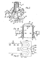
- Figure 1 is a longitudinal cross-sectional view of a compact fluorescent lamp of this invention;
- Figure 2 is a view taken on line II-II of Figure 1;
- Figure 3 is a perspective view of a chassis member of a compact fluorescent lamp of this invention;
- Figure 4 is en enlarged elevational view, partly in cross-section, of a screw base fixed to a chassis member of a compact fluorescent lamp of this invention; and
- Figure 5 is a schematic diagram of an electric circuit embodying this invention.
- Referring now to the drawings, wherein like reference numerals designate identical or corresponding parts through the several views, and more particularly to Figures 1, 2 and 3 thereof, a compact fluorescent lamp 1 has a
chassis member 2, abase member 3 and a non-opaque globe member 4, as shown. Thechassis member 2 is made of heat proof plastics (i.e. polycarbonate resin) and includes acylindrical part 5 at one end thereof. - The
cylindrical part 5 consists of a plurality ofscrew thread portions 6 moulded in an end of astraight portion 7. The length of thesxcrew thread portions 6 of thecylindrical part 5 is less than that of thread portions 8' formed on a screwcap lamp base 8 as used for incandescent lamps (i.e. E - 26 type base). The diameter of thescrew thread portions 6 is only slightly less than that of thestraight portion 7. Moreover, thecylindrical part 5 is formed with opposing longitudinal recesses or slots 9 and alongitudinal slot 10 extends along the entire length of the outer surface thereof. Moreover, as best seen in Figure 3, the outer end of each of the recesses and theslot 10 is open. Astrut 11 is provided accross the open end of thecylindrical part 5 to mechanically reinforce it. - The hemispherical
shaped base member 3, has anupper opening 3a and alower opening 3b, and is attached to thecylindrical part 5 of thechassis member 2. The inside surface of theupper opening 3a is provided withopposing projection parts 12 and the attachment of thecylindrical part 5 to thebase member 3 is accomplished by positioning theprojections 12 of thebase member 3 into the recesses 9 of thechassis member 2. Screwcap lamp base 8 is then fixed by screwing to thescrew thread portions 6 of thecylindrical part 5. - As best seen in Figure 4, a more certain fixing between the screw
cap lamp base 8 and thecylindrical part 5 is achieved by formingfixing projections 8a at the portion of thebase 8 corresponding to the portions of recesses 9 provided at thestraight portion 7 of thecylindrical part 5. Theprojections 8a may be formed by punching the base withpunches 40 oncebase 8 has been positioned on thescrew thread portions 6. - The
base member 3 is provided with a plurality of arc-shaped openings 3' adjacent the lowerperipheral opening 3b. Thelower opening 3b of thebase member 3 is mounted on the bowl-shaped globe member 4 which is made of plastics (i.e. polycarbonate) and coloured, for example white. The globe number 4 has a plurality of openings 4' to permit air to flow into the top thereof. The connection of thebase member 3 to the globe member 4 is achieved by means of co-operatinghook portions base member 3 and the globe member 4. - Two
arm parts 15 are formed at the inner end on thecylindrical part 5 of thechassis member 2. Arectangular holding plate 16 is connected to thearm parts 15. A pair of opposed channel-shapedfixing wall members 17 are mounted on theholding plate 16 so as to face each other. - Between the
fixing wall members 17, the top of aballast 18 is positioned and it is fixed with itslead wires base member 3. The height of thefixing members 17 is from 20 to 25 per cent of the height of theballast 18. Arib 19 is provided inside each of thearm parts 15, not only to reinforce these parts but also to provide a stop face for the top of theballast 18. A foldedenvelope 20 is supported by theholding plate 16 so as to surround theballast 18. The envelope'20 is formed by bending a straight glass tube into a U-shape to form afirst bent part 20a and a pair of first leg parts 20b, followed by the bending once more of each of the pair of leg parts 20b into second U-shapes to form second leg parts 20c and two pairs of second bent parts 20d. The thus foldedenvelope 20 is of a small and compact shape which may be referred to as a saddle shape envelope. Theholding plate 16 also provides ahook arm member 21 extending from aspreader plate 22 to hold thefirst bent part 20a of theenvelope 20 and a maintainingplate 23 havingparts 24 which serve to hold the ends of thewinding envelope 20. Thefirst bent part 20a of theenvelope 20 is maintained between thehook arm member 21 and thespreader plate 22. The maintainingplate 23 is like a flange havingsemicircular pieces 24 at opposite ends which hold the ends of thewinding envelope 20. Theholding plate 16 of thechassis member 2 provides a largeheat shield plate 25 mounted on the maintainingplate 23 and a smallheat shield plate 26 mounted on thespreader plate 22. Consequently, heat from theballast 18 is shielded from thefirst bent part 20a and both ends of thewinding envelope 20 by the large and smallheat shield plates - The
plate 23 also provides a pair ofguide projections 27, each having alongitudinal notch 28 therein, the notches being directed toward the central axis of thecylindrical part 5. Consequently, the notches of theguide projections 27 and theslot 10 of thecylindrical part 5 face each other. Theplate 23 also provides aholder 29 for aglow starter 30 at the centre thereof and directly in front of the largeheat shield plate 25. - The maintaining
plate 23 also inclodes an edge member such as anedge wall 31 along the edge on the same side of the maintaining plate as theguide projections 27. Theedge wall 31 has sufficient height to reduce the clearance formed when thechassis member 2 is attached to thebase member 3 such that fingers cannot be inserted to touch the lead wires. Theedge wall 31 extends to thesemicircular pieces 24. -
Lead wires respective lead wires capacitor 32 by twisting lead wires together, and each of the sets of connectedwires respective lead wires electrodes envelope 20. These sets oflead wires lead wires electrodes cap lamp base 8 and to thelead wire 18a of theballast 18. That is, after thelead wire 33b has been inserted into thenotch 28, it is lead to the screwcap lamp base 8 by way of theslot 10 which requires the shortest travel distance for thelead wire 33b. The end of thelead wire 33b is soldered to the screwcap lamp base 8. Thelead wire 18b of theballast 18 is connected by soldering after being guided through the inside of thecylindrical part 5, to anouter contact 35 of the screwcap lamp base 8. - The inner surface of the
envelope 20 is coated with phosphorus, and a predetermined amount of mercury and inert gases are sealed in theenvelope 20. - In the compact fluorescent lamp, the
longitudinal slot 10 is provided on the cylindrical parts of thechassis member 2. Consequently, since thelead wire 33b is lead to the edge of the screwcap lamp base 8 by way of theslot 10, the movement of thelead wire 33b is checked even when the screwcap lamp base 8 is fixed by screwing to thethread portion 6 of thecylindrical part 5. As the position of thelead wire 33b relative to the screwcap lamp base 8 is uniform, the efficiency of the next manufacturing step is increased. - Since the
notches 28 on theguide projections 27 are directed towards theslot 10 of thecylindrical part 5, thelead wire 33b of theelectrode 33 is not only fixed firmly by inserting it into thenotch 28 but it is lead to theslot 10 by the shortest distance. - As the length of the
thread portions 6 of thecylindrical part 5 is less than that of the thread portions 8' of the screwcap lamp base 8, and the diameter of thethread portions 6 is formed slightly smaller than that of thestraight portion 7, when the screwcap lamp base 8 is attached to thecylindrical part 5, the inside surface of the non-thread portions of the screwcap lamp base 8 and the outside surface of thestraight portion 7 are in surface contact with nach other. Thus, the frictional resistance to turning increases and the fixing of the screwcap lamp base 8 to thecylindrical part 5 becomes, firm and stable. Moreover, by use of apunch 40, the fixing of the screwcap lamp base 8 to thecylindrical part 5 is assured. Such a stable fixing of the screwcap lamp base 8 is desirable in a compact fluorescent lamp which requires high mechanical strength at the screw base portion. - Furthermore, since an
edge wall 31 is provided at the edge of the maintainingplate 23, the lead wires of the foldedenvelope 20, theglow starter 30 and thecapacitor 32 may be held on the maintainingplate 23 and theedge wall 31 prevents these lead wires from protruding beyond the maintainingplate 23. When thechassis member 2 including the maintainingplate 23 is attached to thebase member 3, theedge wall 31 prevents fingers from touching the lead wires. A plurality of projections formed at adequate intervals, instead of theedge wall 31, would of course provide the same function as theedge wall 31. - Obviously, numerous (additional) modifications and variations of the present invention are possible in light of the above teachings. It is therefore to be understood that within the scope of the appended claims, the invention may be practiced otherwise than as specifically described herein.
Claims (6)
Applications Claiming Priority (6)
| Application Number | Priority Date | Filing Date | Title |
|---|---|---|---|
| JP9678480A JPS5721043A (en) | 1980-07-15 | 1980-07-15 | Fluorescent lamp |
| JP96785/80 | 1980-07-15 | ||
| JP96784/80 | 1980-07-15 | ||
| JP9678680A JPS5721064A (en) | 1980-07-15 | 1980-07-15 | Fluorescent lamp |
| JP96786/80 | 1980-07-15 | ||
| JP9678580A JPS5721063A (en) | 1980-07-15 | 1980-07-15 | Fluorescent lamp |
Publications (2)
| Publication Number | Publication Date |
|---|---|
| EP0044196A1 true EP0044196A1 (en) | 1982-01-20 |
| EP0044196B1 EP0044196B1 (en) | 1985-10-09 |
Family
ID=27308211
Family Applications (1)
| Application Number | Title | Priority Date | Filing Date |
|---|---|---|---|
| EP81303116A Expired EP0044196B1 (en) | 1980-07-15 | 1981-07-08 | Compact fluorescent lamp arrangement |
Country Status (4)
| Country | Link |
|---|---|
| US (1) | US4456854A (en) |
| EP (1) | EP0044196B1 (en) |
| AU (1) | AU532236B2 (en) |
| DE (1) | DE3172601D1 (en) |
Cited By (5)
| Publication number | Priority date | Publication date | Assignee | Title |
|---|---|---|---|---|
| EP0144108A3 (en) * | 1983-12-01 | 1985-07-10 | N.V. Philips' Gloeilampenfabrieken | Electrical lamp |
| EP0045182B1 (en) * | 1980-07-28 | 1985-10-23 | Kabushiki Kaisha Toshiba | Compact fluorescent lamp |
| EP0179472A3 (en) * | 1984-10-25 | 1988-10-05 | Patent-Treuhand-Gesellschaft für elektrische Glühlampen mbH | Mercury vapour low-pressure discharge lamp having a single base |
| US6707238B2 (en) | 2001-12-20 | 2004-03-16 | Patent-Treuhand-Gesellschaft Fur Elektrisch Gluhlampen Mbh | Compact low-pressure discharge lamp |
| US6919671B2 (en) | 2001-12-20 | 2005-07-19 | Patent-Treuhand-Gesellschaft Fur Elektrisch Gluhlampen Mbh | Compact low-pressure discharge lamp |
Families Citing this family (4)
| Publication number | Priority date | Publication date | Assignee | Title |
|---|---|---|---|---|
| US5672932A (en) * | 1992-05-04 | 1997-09-30 | Goldman; Dennis | Compact lamp assembly with tubular portions arranged in V-shaped configuration |
| US5390096A (en) * | 1992-10-22 | 1995-02-14 | Progressive Technology In Lighting, Inc. | Replacement compact fluorescent lamp assembly |
| US5720548A (en) * | 1995-11-14 | 1998-02-24 | Progressive Technology In Lighting, Inc. | High luminance fluorescent lamp assembly |
| US20110115372A1 (en) * | 2009-11-17 | 2011-05-19 | General Electric Company | Electric lamp with pin connectors and method of manufacture |
Citations (4)
| Publication number | Priority date | Publication date | Assignee | Title |
|---|---|---|---|---|
| US3070767A (en) * | 1962-02-01 | 1962-12-25 | Rabinow Engineering Co Inc | Socket adapter |
| US3953761A (en) * | 1974-04-03 | 1976-04-27 | Thomas Lo Giudice | Fluorescent light bulb for use in conventional incandescent bulb fixture |
| GB2003314A (en) * | 1977-08-23 | 1979-03-07 | Philips Nv | Lamp unit |
| GB2033653A (en) * | 1978-10-26 | 1980-05-21 | Philips Nv | Low-pressure mercury vapour discharge lamp |
Family Cites Families (9)
| Publication number | Priority date | Publication date | Assignee | Title |
|---|---|---|---|---|
| US3808495A (en) * | 1972-08-21 | 1974-04-30 | Malcolite Corp | Guard for illumination tubes |
| NL179854C (en) * | 1977-08-23 | 1986-11-17 | Philips Nv | LOW-PRESSURE MERCURY DISCHARGE LAMP. |
| US4187446A (en) * | 1977-09-21 | 1980-02-05 | Leo Gross | Screw-in fluorescent lamp with magnetic arc spreading |
| EP0005626B1 (en) * | 1978-05-17 | 1983-10-05 | THORN EMI plc | Cap assemblies for lamps |
| US4165143A (en) * | 1978-08-03 | 1979-08-21 | Gte Sylvania Incorporated | Electron tube socket securing means |
| US4300073A (en) * | 1979-02-13 | 1981-11-10 | Westinghouse Electric Corp. | Screw-in type lighting unit having a convoluted tridimensional fluorescent lamp |
| AU529323B2 (en) * | 1979-09-29 | 1983-06-02 | K.K. Toshiba | Fluorescent lamp |
| US4270071A (en) * | 1979-11-26 | 1981-05-26 | Westinghouse Electric Corp. | Composite base and ballast member for compact single-ended fluorescent lamp |
| US4347460A (en) * | 1980-03-03 | 1982-08-31 | Gte Products Corporation | Compact fluorescent lamp assembly |
-
1981
- 1981-06-30 US US06/279,199 patent/US4456854A/en not_active Expired - Fee Related
- 1981-07-08 DE DE8181303116T patent/DE3172601D1/en not_active Expired
- 1981-07-08 EP EP81303116A patent/EP0044196B1/en not_active Expired
- 1981-07-14 AU AU72873/81A patent/AU532236B2/en not_active Ceased
Patent Citations (4)
| Publication number | Priority date | Publication date | Assignee | Title |
|---|---|---|---|---|
| US3070767A (en) * | 1962-02-01 | 1962-12-25 | Rabinow Engineering Co Inc | Socket adapter |
| US3953761A (en) * | 1974-04-03 | 1976-04-27 | Thomas Lo Giudice | Fluorescent light bulb for use in conventional incandescent bulb fixture |
| GB2003314A (en) * | 1977-08-23 | 1979-03-07 | Philips Nv | Lamp unit |
| GB2033653A (en) * | 1978-10-26 | 1980-05-21 | Philips Nv | Low-pressure mercury vapour discharge lamp |
Cited By (7)
| Publication number | Priority date | Publication date | Assignee | Title |
|---|---|---|---|---|
| EP0045182B1 (en) * | 1980-07-28 | 1985-10-23 | Kabushiki Kaisha Toshiba | Compact fluorescent lamp |
| EP0144108A3 (en) * | 1983-12-01 | 1985-07-10 | N.V. Philips' Gloeilampenfabrieken | Electrical lamp |
| EP0179472A3 (en) * | 1984-10-25 | 1988-10-05 | Patent-Treuhand-Gesellschaft für elektrische Glühlampen mbH | Mercury vapour low-pressure discharge lamp having a single base |
| US6707238B2 (en) | 2001-12-20 | 2004-03-16 | Patent-Treuhand-Gesellschaft Fur Elektrisch Gluhlampen Mbh | Compact low-pressure discharge lamp |
| US6919671B2 (en) | 2001-12-20 | 2005-07-19 | Patent-Treuhand-Gesellschaft Fur Elektrisch Gluhlampen Mbh | Compact low-pressure discharge lamp |
| EP1329932A3 (en) * | 2001-12-20 | 2006-02-01 | Patent-Treuhand-Gesellschaft für elektrische Glühlampen mbH | Compact low pressure discharge lamp |
| EP1329931A3 (en) * | 2001-12-20 | 2006-04-26 | Patent-Treuhand-Gesellschaft für elektrische Glühlampen mbH | Compact low pressure discharge lamp |
Also Published As
| Publication number | Publication date |
|---|---|
| EP0044196B1 (en) | 1985-10-09 |
| US4456854A (en) | 1984-06-26 |
| DE3172601D1 (en) | 1985-11-14 |
| AU532236B2 (en) | 1983-09-22 |
| AU7287381A (en) | 1982-01-21 |
Similar Documents
| Publication | Publication Date | Title |
|---|---|---|
| EP2156463B1 (en) | Compact fluorescent lamp with outer envelope and method for manufacturing such lamp | |
| EP0044195B1 (en) | Compact fluorescent lamp arrangement | |
| US8436538B2 (en) | Compact fluorescent lamp with mechanical support means and starting aid | |
| EP0044196B1 (en) | Compact fluorescent lamp arrangement | |
| EP0748516B1 (en) | Electric lamp | |
| US4878854A (en) | Lamp base | |
| CA1180748A (en) | Compact fluorescent lamp | |
| KR900008205B1 (en) | Fluorescent lamp having the winding discharge path and method of the same | |
| US5432690A (en) | Luminaire | |
| JPH10208622A (en) | Compact low-pressure discharge lamp | |
| US4854888A (en) | Lamp base | |
| US4454451A (en) | Circular fluorescent lamp unit | |
| CA1176300A (en) | Compact fluorescent lamp | |
| JP3324569B2 (en) | Low pressure mercury vapor discharge lamp | |
| US7012373B2 (en) | Electronic energy-saving fluorescent lamp of ultra-short chayote-shaped compact type | |
| JP3149905B2 (en) | Bulb-type fluorescent lamp | |
| JPS6228524B2 (en) | ||
| JPH04167327A (en) | Fluorescent lamp device | |
| JPS5939364Y2 (en) | fluorescent lamp device | |
| US5834884A (en) | Systematic configuration of compact fluorescent lamps for operation in a single-type ballast | |
| JPH0229604Y2 (en) | ||
| JPS6248323B2 (en) | ||
| JP2947865B2 (en) | Fluorescent lamp base | |
| JPS5941566Y2 (en) | fluorescent lamp device | |
| CA1205848A (en) | Circular fluorescent lamp unit |
Legal Events
| Date | Code | Title | Description |
|---|---|---|---|
| PUAI | Public reference made under article 153(3) epc to a published international application that has entered the european phase |
Free format text: ORIGINAL CODE: 0009012 |
|
| AK | Designated contracting states |
Designated state(s): DE FR GB IT NL |
|
| 17P | Request for examination filed |
Effective date: 19820619 |
|
| RAP1 | Party data changed (applicant data changed or rights of an application transferred) |
Owner name: KABUSHIKI KAISHA TOSHIBA |
|
| GRAA | (expected) grant |
Free format text: ORIGINAL CODE: 0009210 |
|
| AK | Designated contracting states |
Designated state(s): DE FR GB IT NL |
|
| ET | Fr: translation filed | ||
| REF | Corresponds to: |
Ref document number: 3172601 Country of ref document: DE Date of ref document: 19851114 |
|
| ITF | It: translation for a ep patent filed | ||
| PLBE | No opposition filed within time limit |
Free format text: ORIGINAL CODE: 0009261 |
|
| STAA | Information on the status of an ep patent application or granted ep patent |
Free format text: STATUS: NO OPPOSITION FILED WITHIN TIME LIMIT |
|
| 26N | No opposition filed | ||
| REG | Reference to a national code |
Ref country code: GB Ref legal event code: 746 |
|
| PGFP | Annual fee paid to national office [announced via postgrant information from national office to epo] |
Ref country code: GB Payment date: 19910701 Year of fee payment: 11 |
|
| PGFP | Annual fee paid to national office [announced via postgrant information from national office to epo] |
Ref country code: FR Payment date: 19910721 Year of fee payment: 11 |
|
| ITTA | It: last paid annual fee | ||
| PGFP | Annual fee paid to national office [announced via postgrant information from national office to epo] |
Ref country code: NL Payment date: 19910731 Year of fee payment: 11 |
|
| PGFP | Annual fee paid to national office [announced via postgrant information from national office to epo] |
Ref country code: DE Payment date: 19910830 Year of fee payment: 11 |
|
| PG25 | Lapsed in a contracting state [announced via postgrant information from national office to epo] |
Ref country code: GB Effective date: 19920708 |
|
| PG25 | Lapsed in a contracting state [announced via postgrant information from national office to epo] |
Ref country code: NL Effective date: 19930201 |
|
| GBPC | Gb: european patent ceased through non-payment of renewal fee |
Effective date: 19920708 |
|
| NLV4 | Nl: lapsed or anulled due to non-payment of the annual fee | ||
| PG25 | Lapsed in a contracting state [announced via postgrant information from national office to epo] |
Ref country code: FR Effective date: 19930331 |
|
| PG25 | Lapsed in a contracting state [announced via postgrant information from national office to epo] |
Ref country code: DE Effective date: 19930401 |
|
| REG | Reference to a national code |
Ref country code: FR Ref legal event code: ST |