EP0044067A2 - Collimator assembly for an electron accelerator - Google Patents
Collimator assembly for an electron accelerator Download PDFInfo
- Publication number
- EP0044067A2 EP0044067A2 EP81105468A EP81105468A EP0044067A2 EP 0044067 A2 EP0044067 A2 EP 0044067A2 EP 81105468 A EP81105468 A EP 81105468A EP 81105468 A EP81105468 A EP 81105468A EP 0044067 A2 EP0044067 A2 EP 0044067A2
- Authority
- EP
- European Patent Office
- Prior art keywords
- collimator
- ray
- inserts
- cone
- insert
- Prior art date
- Legal status (The legal status is an assumption and is not a legal conclusion. Google has not performed a legal analysis and makes no representation as to the accuracy of the status listed.)
- Granted
Links
Images
Classifications
-
- G—PHYSICS
- G21—NUCLEAR PHYSICS; NUCLEAR ENGINEERING
- G21K—TECHNIQUES FOR HANDLING PARTICLES OR IONISING RADIATION NOT OTHERWISE PROVIDED FOR; IRRADIATION DEVICES; GAMMA RAY OR X-RAY MICROSCOPES
- G21K1/00—Arrangements for handling particles or ionising radiation, e.g. focusing or moderating
- G21K1/02—Arrangements for handling particles or ionising radiation, e.g. focusing or moderating using diaphragms, collimators
-
- A—HUMAN NECESSITIES
- A61—MEDICAL OR VETERINARY SCIENCE; HYGIENE
- A61B—DIAGNOSIS; SURGERY; IDENTIFICATION
- A61B6/00—Apparatus for radiation diagnosis, e.g. combined with radiation therapy equipment
- A61B6/08—Auxiliary means for directing the radiation beam to a particular spot, e.g. using light beams
-
- H—ELECTRICITY
- H05—ELECTRIC TECHNIQUES NOT OTHERWISE PROVIDED FOR
- H05H—PLASMA TECHNIQUE; PRODUCTION OF ACCELERATED ELECTRICALLY-CHARGED PARTICLES OR OF NEUTRONS; PRODUCTION OR ACCELERATION OF NEUTRAL MOLECULAR OR ATOMIC BEAMS
- H05H7/00—Details of devices of the types covered by groups H05H9/00, H05H11/00, H05H13/00
- H05H7/22—Details of linear accelerators, e.g. drift tubes
Abstract
Description
- This invention relates to an electron accelerator including a target exposed to the electron beam for the purpose of producing X-ray radiation and a collimator assembly limiting or defining the X-ray cone. More particularly, this invention relates to a collimator assembly for an electron accelerator, the collimator assembly comprising a collimator shielding block for blocking undesired X-rays and an insert piece or bushing inserted into the shielding block for defining the cone of the X-ray beam.
- In radiation-therapy, the X-ray cone issuing from an electron accelerator should have a dose rate or intensity of equal magnitude over its entire cross-section. This is necessary in order to be able to apply the minimum dose required for destroying the diseased tissue in the region of the seat of the disease, and at the same time to be able to spare the adjacent healthy tissue.
- In electron accelerators the X-ray radiation is produced in a target by accelerated electrons. The dose rate in the X-ray cone being issued has a conical characteristic with a maximum in the direction in which the electron beam impinges upon the target. This maximum most often coincides with the symmetry axis of the collimator.
- From U.S. Patent No. 4,157,475 it is known to obtain an equal intensity or dose rate distribution across the X-ray cone defined by the collimator assembly by installing a compensating member or flattening filter in the X-ray cone. This flattening filter has a conical construction. It is adapted in its form and in its radiation absorption properties to the characteristic of the dose rate at its point of application. Behind the flattening filter an X-ray cone is obtained having a dose rate of equal magnitude at a fixed tissue depth (for
instance 10 cm) over the entire cross-section of the X-ray cone. At a lesser tissue depth (for instance 3 cm) the dose rate would increase from the interior toward the exterior, i.e. radially from the axis, (nonuniform dose rate distribution). This could lead to a greater dose charge on the healthy tissue. In order to avoid the undesired excessive increase in the dose rate in the marginal region of the X-ray cone at a lesser tissue depth, it is known from U.S. Patent No. 4,156,475 to roughen the interior wall surfaces of the collimator which limit the X-ray cone and define a conical passageway for the X-ray cone, in a direction transverse to the radiation direction. Particularly, stepped grooves may be introduced into the interior wall surfaces , these grooves being arranged transversely to the radiation direction. The inner wall surfaces may be grooved such as to provide axially spaced relatively narrow annular ridge portions each conforming to the perimeter of the conical passageway and relatively wide annular intermediate wall portions providing groove regions such that the annular intermediate wall portions extend outwardly and are clear of the perimeter of the conical passageway. Each groove region may have a width dimension measured along the conical passageway which greatly exceeds the width of the annular ridge portions, but is not greater than about five millimeters. The ridge portions may have a slight pitch in the radiation direction in the manner of a screw thread. Due to the stepped grooves, there is a displacement of scatter locations to greater depths of the material. The quanta scattered at an acute angle are strongly absorbed in the edges of the grooves. - From U.S. Patent No. 4,157,475 it is also known to admit the step-shaped grooves into a sleeve or bushing. This bushing is inserted in a fixed manner into the collimator shielding block. The bushing is not intended to be removed. The bushing consists of a material of low atomic number, such as, for example, iron, copper, or aluminum, whose atomic number is less than that of the collimator shielding block. Accordingly, the forward scattering is more pronounced in this material.
- Due to the fixed brushing and in accordance with the fixed dimensions of the passageway, the collimator assembly has a certain maximum X-ray field size. Smaller fields may be obtained by means of adjustable X-ray shielding plates which are arranged behind the collimator assembly.
- In medical applications tissues of various sizes are irradiated by X-rays. In such applications it seems desirable to have available a collimator assembly that allows for various maximum X-ray field sizes. Removing the total collimator assembly and replacing it by another one having different dimensions of its X-ray passageway is time consumming, tedious and expensive.
- Compensating or flattening filters are known from Rev. Scient. Instr. 27, 1956, p. 584.
- An object of this invention is to provide a collimator assembly for a linear accelerator which allows for application of various X-ray field sizes without removing and/or replacing the total collimator assembly.
- Another object of this invention is to provide a collimator assembly for a linear accelerator which can be easily adapted to various sizes of morbid tissues which are to be exposed to the X-ray field of the accelerator.
- Still another object of this invention is to provide a collimator assembly for a linear accelerator that defines an X-ray cone having a dose rate of equal magnitude over its entire cross-section at various tissue depths of a patient, wherein the collimator assembly comprises a collimator shielding block and an insert piece or bushing which is readily inserted into said block and which may easily be machined.
- Still another object of this invention is to provide a collimator assembly having interchangeable passageways, wherein the process of interchanging does not require expensive and time-consuming adjustments.
- Still another object of this invention is to provide a collimator assembly having interchangeable inserts which can be used in linear accelerators of different electron energy levels.
- According to this invention, the collimator assembly comprises a collimator shielding block for blocking undesired X-rays and a bushing inserted into the shielding block. The bushing has a conical passage opening for transmitting X-rays therethrough and for defining the X-ray cone. There are provided means for easily interchanging the bushing in the collimator shielding block. Therefore, bushings of different cone-defining passage openings can be inserted readily into the shielding block. If a larger area is to be irradiated, a bushing will be used which has a passageway of a larger cone angle.
- In a preferred embodiment having a simple configuration, there is provided a thread on the bushing and a corresponding thread in the shielding block. Thus, the bushing can be threadibly engaged with the shielding block. It can easily be replaced by another bushing having different dimensions of its passage opening.
- The bushing should be made of a material having a high atomic number. Thus, the bushing is part of the X-ray shield which incorporates also the X-ray shielding block. The bushing may consist of the same material as the collimator shielding block, for instance, a material containing tungsten.
- The foregoing and other objects, features and advantages of the invention will be apparent from the following more particular description of preferred embodiments of the invention, as illustrated in the accompanying drawings.
- The term "bushing" is intended to mean an insert piece or insert herein.
- In the drawings:
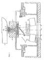
- Fig. 1 is a cross-section of a beam-defining system of an electron accelerator;
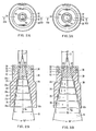
- Fig. 2 is a cross-section of a first interchangeable bushing or insert, which can be used in the collimator assembly illustrated in Fig. 1; and
- Fig. 3 is a cross-section of a second interchangeable bushing or insert, which can also be used in the collimator assembly illustrated in Fig. 1.
- Fig. 1 affords a view of the relative positions of the exit window 1 of a
vaccum envelope 2, of a target 3 for generating X-rays when hit by high energy electrons e , acollimator system 4, and a conical flattening filter 5, in an X-ray beam defining system 6 of an electron accelerator. The target 3 is arranged on a target body 3a in the radiation direction directly behind the exit window 1 of thevaccum envelope 2. The target 3 is mounted within a cylindrical opening or bore 7 of a carrying plate 8. The carrying plate 8 is part of a slide 8a for removing the target 3 out of the electron path. Disposed in the lower end of the target body 3a is anabsorption member 9, arranged in the radiation direction behind the target 3, to absorb the remaining electrons which are not absorbed in the target 3. - The
collimator system 4 is disposed in the radiation direction directly behind the carrying plate 8 of the target 3. Saidcollimator system 4 comprises a thick walled collimator shielding block orcollimator 10, an interchangeable . bushing or insert 10a which is inserted into an insert opening of thecollimator 10 and which has a stepped passage opening 11, andX-ray shielding plates maximum X-ray cone 15. - The insert 10a is introduced into and secured within the
collimator 10 by means ofcorresponding threads 10b. Thesethreads 10b are located on the lower outer part of the bushing 10a and inside the lower part of the insert opening in thecollimator 10, respectively. - Between the passage opening 11 of the collimator insert 10a and the adjustable
X-ray shielding plates - The flattening filter 5 is mounted such that it projects inwardly into the stepped passage opening 11 of the collimator insert 10a. It is centered relative to the central ray or beam axis lla which generally corresponds to the symmetry axis of
collimator system 4. More details of the insert 10a are shown in Figs. 2 and 3. - As can be seen in Figs. 2 and 3, the inner wall surface of the insert 10a contains five stepped
annular grooves usual size collimator 10 normally used can be from four to six to achieve favorable results. Under special circumstances the number of grooves can be higher or lower. The grooves 22 to 26 have a cylindrical shape. The diameter of the grooves 22 to 26 is increased respectively from the top to the bottom of the insert 10a so as to produce a norm which is conical in cross-section. - Comparing the two inserts 10a illustrated in Figs. 2 and 3, respectively, it may be seen that in Fig. 2 the highest groove 22 has a diameter dl which is smaller than the diameter d2 of the highest groove 22 in Fig. 3, .and in in Fig. 2 the
lowest groove 26 has a diameter Dl which is smaller than the diameter D2 of thelowest groove 26 in Fig. 3. Thus as may be seen, the passage opening 11 of the insert 10a of Fig. 2 may form a conical angle of α=18°, for instance, while the passage opening 11 of Fig. 3 may have an angle of a=25°, as an example. The inserts 10a of Figs. 2 and 3 are determined for different field sizes of the X-ray beam in the patient plane. For instance, the beam of Fig. 2 may have a diameter of 37 mm in the patient plane, while the beam of Fig. 3 may have a diameter of 50 cm. - The widths of the
grooves 23 to 26, measured in the radiation direction of the X-rays, may be between 1 and 2 centimeters. For instance, it was found that a width of 1.4 centimeters may be chosen when five grooves 22 to 26 are selected. This value is higher than in structures formerly presented. - The cylindrical grooves 22 to 26 are simple to manufacture. It should be noted that their lower edge is beveled to provide relatively narrow annular rim portions 22a to 26a, respectively. These rim portions 22a to 26a form the conical perimeter of the passageway 11. As mentioned above, due to the dimensions chosen in the illustrated embodiments, the insert 10a in Fig. 2 may have a cone angle of α=l8°, and the insert 10a of Fig. 3 may have a cone angle of α=25°. The cone angle a determines the maximum field size of the X-ray fields. Inserts 10a of various cone angles a may be provided. By interchanging the inserts 10a in the
collimator 10, an appropriate field size may be selected. - The insert 10a consists of a material of high atomic number, such as, for example, tungsten or tungsten alloy, whose atomic number is comparable with or equal to that of the material of the
collimator shielding block 10. Accordingly, the insert 10a is part of the X-ray shielding device of the linear accelerator. - Electrons e of high energy are generated by acceleration within the linear accelerator. The X-ray radiation is produced by collision of the accelerated electrons with the target 3. The X-ray radiation has a specific intensity characteristic which will be referred to as conical. Its intensity maximum coincides with the direction of the impinging electron beam. The flattening filter 5 installed in the
collimator system 4 is precisely adapted with regard to its absorption value and its shape to the intensity characteristic of the X-ray radiation issuing from the target 3. Accordingly, the intensity of theX-ray beam cone 15, with the exception of the marginal regions, is flattened by the flattening filter 5 over the radiation cross-section, so that a unified intensity distribution will result. In other words, the flattening filter 5 helps to provide an X-ray beam of uniform intensity across the cross-section on a patient to be treated. - On the marginal region of the
X-ray beam cone 15, the intensity would be excessively increased over an annular area of the cone cross-section at low tissue depths, if a smooth conical passage opening 11 were used. However, due to the grooves 22 to 26 disposed transversely to the radiation direction in the passage opening 11, such an intensity increase is virtually eliminated. - As can be seen in Figs. 2 and 3, the inserts 10a.. have different cone angles a, yet the same outside appearance (length, diameter, etc.). They are each formed by a cylindrical piece having an upper and a lower cylindrical portion. The diameter of the upper portion is smaller than the diameter of the lower portion, thus forming a shoulder 20 midway on the outer surface. The
thread 10b is located on the lower part of the lower portion. The insert 10a is inserted into thecollimator 10 from below when the filter 5 and the dose chamber 16 are removed. This is an important feature of the illustrated design, since the insert 10a can thus be easily interchanged without disconnecting or moving heavy parts of the linear accelerator. - In the upper face of the insert 10a facing the target 3 is arranged a
cylindrical recess 30. Thisrecess 30 has a larger diameter than the highest groove 22. Located in thisrecess 30 is a ring-shaped or annular piece or plug 32 which may be made of stainless steel or titanium. Generally speaking, it is made of a material of low Effective cross-section for gamma/neutron processes. The thickness of this ring-shapedplug 32, measured in the radiation direction of the X-rays, may correspond to the half-value depth for X-rays. Theplug 32 serves to reduce the production of undesired neutrons. It is secured in its position by twohorizontal pins plug 32 is provided acylindrical electron absorber 38 which may be made, for instance, of aluminum. Theelectron absorber 38 is stepped and inserted from below, that is from the passage opening 11. It is secured on theplug 32 by asnap ring 40. Thesnap ring 40 is arranged in anupper recess 42 of theplug 32. The length of theelectron absorber 38 is selected according to the energy of the accelerated electrons. - As can be seen in Figs. 2 and 3, the insert 10a along with the plug 32-and the
electron absorber 38 form a interchangeable unit. Therefore, in manufacturing linear accelerators a multitude of such units can be provided, and a particular accelerator which is laid out for a specific energy level can be equipped with a specific unit which is chosen in accordance with the selected energy level. Thus, the application of inserts may facilitate the standardization of production. - While the form of the collimator assembly herein described constitutes a preferred embodiment of the invention, it is to be understood that the invention is not limited to this precise form of assembly, and that a variety of changes may be made therein without departing from the scope of the invention.
Claims (8)
Applications Claiming Priority (2)
| Application Number | Priority Date | Filing Date | Title |
|---|---|---|---|
| US168169 | 1980-07-14 | ||
| US06/168,169 US4343997A (en) | 1980-07-14 | 1980-07-14 | Collimator assembly for an electron accelerator |
Publications (3)
| Publication Number | Publication Date |
|---|---|
| EP0044067A2 true EP0044067A2 (en) | 1982-01-20 |
| EP0044067A3 EP0044067A3 (en) | 1982-01-27 |
| EP0044067B1 EP0044067B1 (en) | 1984-05-16 |
Family
ID=22610408
Family Applications (1)
| Application Number | Title | Priority Date | Filing Date |
|---|---|---|---|
| EP81105468A Expired EP0044067B1 (en) | 1980-07-14 | 1981-07-13 | Collimator assembly for an electron accelerator |
Country Status (4)
| Country | Link |
|---|---|
| US (1) | US4343997A (en) |
| EP (1) | EP0044067B1 (en) |
| CA (1) | CA1164108A (en) |
| DE (1) | DE3163631D1 (en) |
Cited By (2)
| Publication number | Priority date | Publication date | Assignee | Title |
|---|---|---|---|---|
| EP0056552A2 (en) * | 1981-01-16 | 1982-07-28 | Thomson-Csf | X-ray tube containing a universal limiter for secondary radiation |
| FR2533829A1 (en) * | 1982-10-04 | 1984-04-06 | Varian Associates | COMBINED COLLIMATOR DEVICE FOR RADIATION DISCHARGE THERAPY |
Families Citing this family (13)
| Publication number | Priority date | Publication date | Assignee | Title |
|---|---|---|---|---|
| JP2615667B2 (en) * | 1987-09-28 | 1997-06-04 | 日産自動車株式会社 | Method of manufacturing MOS field effect transistor |
| US5216255A (en) * | 1992-03-31 | 1993-06-01 | Siemens Medical Laboratories | Beam profile generator for photon radiation |
| US5332908A (en) * | 1992-03-31 | 1994-07-26 | Siemens Medical Laboratories, Inc. | Method for dynamic beam profile generation |
| JPH10178297A (en) * | 1996-12-17 | 1998-06-30 | Taiyo Yuden Co Ltd | Part take-in mechanism for part feeder |
| SE524458C2 (en) * | 2002-03-01 | 2004-08-10 | Mamea Imaging Ab | Protective device by an X-ray apparatus |
| GB2418828B (en) * | 2004-09-30 | 2008-07-09 | Elekta Ab | Anti reflective stepped profile for surfaces of radiotherapeutic apparatus |
| US8017926B2 (en) * | 2008-10-09 | 2011-09-13 | Battelle Energy Allliance, LLC | Radiation collimator and systems incorporating same |
| GB201414393D0 (en) | 2014-08-13 | 2014-09-24 | Nikon Metrology Nv | Z-ray beam collimator |
| US9805904B2 (en) | 2014-11-12 | 2017-10-31 | Schlumberger Technology Corporation | Radiation generator with field shaping electrode |
| US9791592B2 (en) * | 2014-11-12 | 2017-10-17 | Schlumberger Technology Corporation | Radiation generator with frustoconical electrode configuration |
| CN105931694B (en) * | 2016-05-06 | 2018-05-22 | 东莞中子科学中心 | A kind of high-performance neutron howitzer and its assemble method |
| US11456147B2 (en) | 2017-06-23 | 2022-09-27 | Chrysos Corporation Limited | Shielded X-ray radiation apparatus |
| CN219440462U (en) * | 2021-12-30 | 2023-08-01 | 中硼(厦门)医疗器械有限公司 | Coupling assembling, collimator and neutron capture treatment device |
Citations (8)
| Publication number | Priority date | Publication date | Assignee | Title |
|---|---|---|---|---|
| US3040175A (en) * | 1959-09-25 | 1962-06-19 | Baird Atomic Inc | Penetrative radiation collimator |
| GB1110894A (en) * | 1965-03-25 | 1968-04-24 | Euratom | Neutron collimator with variable passage cross-section |
| GB1149063A (en) * | 1965-08-17 | 1969-04-16 | Euratom | Collimator |
| US3539813A (en) * | 1967-11-24 | 1970-11-10 | Varian Associates | Beam width defining structure for linear accelerator radiotherapy devices |
| FR2379294A1 (en) * | 1977-02-08 | 1978-09-01 | Cgr Mev | NEUTRONIC RADIOTHERAPY DEVICE USING A LINEAR PARTICLE ACCELERATOR |
| US4121109A (en) * | 1977-04-13 | 1978-10-17 | Applied Radiation Corporation | Electron accelerator with a target exposed to the electron beam |
| FR2406889A1 (en) * | 1977-10-21 | 1979-05-18 | Siemens Ag | ELECTRON ACCELERATOR |
| DE3017745A1 (en) * | 1979-05-14 | 1980-11-27 | Varian Associates | X-RAY FILTER |
Family Cites Families (4)
| Publication number | Priority date | Publication date | Assignee | Title |
|---|---|---|---|---|
| US2998526A (en) * | 1959-07-17 | 1961-08-29 | Picker X Ray Corp | Head and cone support for therapeutic mechanism |
| US3407300A (en) * | 1966-04-14 | 1968-10-22 | Picker Corp | Collimator and method of making same |
| US3781564A (en) * | 1973-02-28 | 1973-12-25 | Elliott Bros | Neutron beam collimators |
| DE2759073C3 (en) * | 1977-12-30 | 1981-10-22 | Siemens AG, 1000 Berlin und 8000 München | Electron tube |
-
1980
- 1980-07-14 US US06/168,169 patent/US4343997A/en not_active Expired - Lifetime
-
1981
- 1981-07-13 DE DE8181105468T patent/DE3163631D1/en not_active Expired
- 1981-07-13 CA CA000381584A patent/CA1164108A/en not_active Expired
- 1981-07-13 EP EP81105468A patent/EP0044067B1/en not_active Expired
Patent Citations (8)
| Publication number | Priority date | Publication date | Assignee | Title |
|---|---|---|---|---|
| US3040175A (en) * | 1959-09-25 | 1962-06-19 | Baird Atomic Inc | Penetrative radiation collimator |
| GB1110894A (en) * | 1965-03-25 | 1968-04-24 | Euratom | Neutron collimator with variable passage cross-section |
| GB1149063A (en) * | 1965-08-17 | 1969-04-16 | Euratom | Collimator |
| US3539813A (en) * | 1967-11-24 | 1970-11-10 | Varian Associates | Beam width defining structure for linear accelerator radiotherapy devices |
| FR2379294A1 (en) * | 1977-02-08 | 1978-09-01 | Cgr Mev | NEUTRONIC RADIOTHERAPY DEVICE USING A LINEAR PARTICLE ACCELERATOR |
| US4121109A (en) * | 1977-04-13 | 1978-10-17 | Applied Radiation Corporation | Electron accelerator with a target exposed to the electron beam |
| FR2406889A1 (en) * | 1977-10-21 | 1979-05-18 | Siemens Ag | ELECTRON ACCELERATOR |
| DE3017745A1 (en) * | 1979-05-14 | 1980-11-27 | Varian Associates | X-RAY FILTER |
Cited By (5)
| Publication number | Priority date | Publication date | Assignee | Title |
|---|---|---|---|---|
| EP0056552A2 (en) * | 1981-01-16 | 1982-07-28 | Thomson-Csf | X-ray tube containing a universal limiter for secondary radiation |
| EP0056552A3 (en) * | 1981-01-16 | 1982-08-04 | Thomson-Csf | Universal limiter for secondary radiation in an x-ray tube and an x-ray tube containing such a limiter |
| FR2533829A1 (en) * | 1982-10-04 | 1984-04-06 | Varian Associates | COMBINED COLLIMATOR DEVICE FOR RADIATION DISCHARGE THERAPY |
| GB2128460A (en) * | 1982-10-04 | 1984-04-26 | Varian Associates | Collimation system for electron arc therapy |
| US4598208A (en) * | 1982-10-04 | 1986-07-01 | Varian Associates, Inc. | Collimation system for electron arc therapy |
Also Published As
| Publication number | Publication date |
|---|---|
| CA1164108A (en) | 1984-03-20 |
| EP0044067B1 (en) | 1984-05-16 |
| DE3163631D1 (en) | 1984-06-20 |
| EP0044067A3 (en) | 1982-01-27 |
| US4343997A (en) | 1982-08-10 |
Similar Documents
| Publication | Publication Date | Title |
|---|---|---|
| US4359642A (en) | Collimator assembly for an electron accelerator | |
| US4343997A (en) | Collimator assembly for an electron accelerator | |
| US11749418B2 (en) | Strontium sealed source | |
| US4157475A (en) | Electron accelerator comprising a target exposed to the electron beam | |
| EP2711048B1 (en) | Device for generating beams of converging x-photons | |
| RU2734955C1 (en) | Beam forming unit for neutron capturing therapy | |
| CN107485801B (en) | Collimation body and treatment head | |
| US6813336B1 (en) | High definition conformal arc radiation therapy with a multi-leaf collimator | |
| US20210031053A1 (en) | Radiation treatment head and radiation treatment device | |
| EP3957363A1 (en) | Neutron capture therapy system | |
| Georg et al. | Dosimetric comparison of an integrated multileaf-collimator versus a conventional collimator | |
| US4327293A (en) | Electron accelerator and target with collimator | |
| US11185713B2 (en) | IORT device for radiotherapy treatment of cancer patients | |
| EP0811991A1 (en) | Collimators | |
| US8971491B2 (en) | System and method for improved radiosurgery collimation | |
| US20230317310A1 (en) | Flash electron applicator with integrated dosimeter | |
| JP2003079753A (en) | Radiotherapy equipment | |
| Mayles | Kilovoltage X-Ray Beams | |
| Taumann | The treatment head design for medical linear accelerators | |
| Braun et al. | Electron beam modifiers for inlraoperative radiation teorapy (IORT) cones | |
| JPH04367669A (en) | Radiation treating device |
Legal Events
| Date | Code | Title | Description |
|---|---|---|---|
| PUAI | Public reference made under article 153(3) epc to a published international application that has entered the european phase |
Free format text: ORIGINAL CODE: 0009012 |
|
| PUAL | Search report despatched |
Free format text: ORIGINAL CODE: 0009013 |
|
| AK | Designated contracting states |
Designated state(s): DE FR GB SE |
|
| AK | Designated contracting states |
Designated state(s): DE FR GB SE |
|
| 17P | Request for examination filed |
Effective date: 19820727 |
|
| GRAA | (expected) grant |
Free format text: ORIGINAL CODE: 0009210 |
|
| AK | Designated contracting states |
Designated state(s): DE FR GB SE |
|
| REF | Corresponds to: |
Ref document number: 3163631 Country of ref document: DE Date of ref document: 19840620 |
|
| ET | Fr: translation filed | ||
| PLBE | No opposition filed within time limit |
Free format text: ORIGINAL CODE: 0009261 |
|
| STAA | Information on the status of an ep patent application or granted ep patent |
Free format text: STATUS: NO OPPOSITION FILED WITHIN TIME LIMIT |
|
| 26N | No opposition filed | ||
| EAL | Se: european patent in force in sweden |
Ref document number: 81105468.3 |
|
| PGFP | Annual fee paid to national office [announced via postgrant information from national office to epo] |
Ref country code: SE Payment date: 20000713 Year of fee payment: 20 Ref country code: GB Payment date: 20000713 Year of fee payment: 20 |
|
| PGFP | Annual fee paid to national office [announced via postgrant information from national office to epo] |
Ref country code: FR Payment date: 20000718 Year of fee payment: 20 |
|
| PGFP | Annual fee paid to national office [announced via postgrant information from national office to epo] |
Ref country code: DE Payment date: 20000918 Year of fee payment: 20 |
|
| PG25 | Lapsed in a contracting state [announced via postgrant information from national office to epo] |
Ref country code: GB Free format text: LAPSE BECAUSE OF EXPIRATION OF PROTECTION Effective date: 20010712 |
|
| PG25 | Lapsed in a contracting state [announced via postgrant information from national office to epo] |
Ref country code: SE Free format text: THE PATENT HAS BEEN ANNULLED BY A DECISION OF A NATIONAL AUTHORITY Effective date: 20010714 |
|
| REG | Reference to a national code |
Ref country code: GB Ref legal event code: PE20 Effective date: 20010712 |
|
| EUG | Se: european patent has lapsed |
Ref document number: 81105468.3 |