EP0043915B1 - Method for continuously welding a plurality of tubes disposed in multiple rows to a tube sheet - Google Patents
Method for continuously welding a plurality of tubes disposed in multiple rows to a tube sheet Download PDFInfo
- Publication number
- EP0043915B1 EP0043915B1 EP81104493A EP81104493A EP0043915B1 EP 0043915 B1 EP0043915 B1 EP 0043915B1 EP 81104493 A EP81104493 A EP 81104493A EP 81104493 A EP81104493 A EP 81104493A EP 0043915 B1 EP0043915 B1 EP 0043915B1
- Authority
- EP
- European Patent Office
- Prior art keywords
- tubes
- tube
- welding
- tube sheet
- weld
- Prior art date
- Legal status (The legal status is an assumption and is not a legal conclusion. Google has not performed a legal analysis and makes no representation as to the accuracy of the status listed.)
- Expired
Links
Images


Classifications
-
- B—PERFORMING OPERATIONS; TRANSPORTING
- B23—MACHINE TOOLS; METAL-WORKING NOT OTHERWISE PROVIDED FOR
- B23K—SOLDERING OR UNSOLDERING; WELDING; CLADDING OR PLATING BY SOLDERING OR WELDING; CUTTING BY APPLYING HEAT LOCALLY, e.g. FLAME CUTTING; WORKING BY LASER BEAM
- B23K9/00—Arc welding or cutting
- B23K9/02—Seam welding; Backing means; Inserts
- B23K9/028—Seam welding; Backing means; Inserts for curved planar seams
- B23K9/0288—Seam welding; Backing means; Inserts for curved planar seams for welding of tubes to tube plates
-
- B—PERFORMING OPERATIONS; TRANSPORTING
- B23—MACHINE TOOLS; METAL-WORKING NOT OTHERWISE PROVIDED FOR
- B23K—SOLDERING OR UNSOLDERING; WELDING; CLADDING OR PLATING BY SOLDERING OR WELDING; CUTTING BY APPLYING HEAT LOCALLY, e.g. FLAME CUTTING; WORKING BY LASER BEAM
- B23K2101/00—Articles made by soldering, welding or cutting
- B23K2101/04—Tubular or hollow articles
- B23K2101/14—Heat exchangers
Definitions
- This invention relates to a method of welding tubes to a tube sheet of a heat exchanger and more particularly to a method of continuously welding tubes in a plurality of rows utilizing a continuous weld.
- US-A-4161646 discloses the use of a continuous electron beam in a similar application.
- An obstruction to continuous welds is that tubes are not disposed on exactly even pitches and the tube sheet holes including the tubes expanded therein do not always have exactly the same size so that it is difficult to position the welding equipment for accurate welding.
- the present invention resides in a method for welding at least a portion of multiple rows of tubes to a tube sheet utilizing apparatus which under the control of a recorded program can automatically drive a welding means to any predetermined X and Y position encompassing said portion of said multiple rows of tubes, a continuous weld being formed following a predetermined path which extends about the periphery of each tube having its X and Y positions recorded to weld said tubes to the tube sheet, characterized in that the welding means is a welding torch, and in that before welding, a tapered probe secured to said apparatus is placed into each tube to be welded to the tube sheet and the X and Y positions of each tube are recorded, and that said probe is firmly pressed into the respective tubes so as to be centered therein and that the depth of insertion of said tapered probe into said tubes is also recorded and determined as an indication of the diameter of the tube and the welding path around a tube is modified to compensate for variations in the tubes' predetermined locations and diameters.
- a hoist 9 is disposed above the heat exchanger and rolls on a beam 11 supported by the columns 12. The hoist 9 supports continuous welding apparatus 13 for continuously welding a portion of a plurality of rows of tubes.
- the continuous welding apparatus 13 comprises a base 15 and means 17 for attaching the base 15 to the tube sheet 1.
- the means 17 for attaching the base 15 to the tube sheet 1 comprises an elastomer sleeve 19 which is compressed axially by a pneumatic or hydraulic cylinder 21 to expand the elastomer sleeve 19 into radial engagement with a tube or tube hole. While only one such attaching means is shown, another such means is disposed diagonally opposite the one shown but cannot be seen in the drawing.
- a carriage 23 is slidably disposed on the base 15 so as to move rectilinearly in Y direction and a stepping motor drive 25 rotates a screw (not shown), which engages a split nut (not shown) which can be made to engage and disengage the screw by moving a lever 27 disposed on the carriage allowing free or controlled movement of the carriage 23 in the Y direction depending on whether or not the split nut engages the screw.
- a linear encoder 29 is utilized to signal the Y position of the carriage 23.
- a crossfeed frame 31 Slidably disposed on the carriage 23 is a crossfeed frame 31 which is so disposed thereon to move rectilinearly in the X direction.
- a stepping motor drive 33 rotates a screw 35 which engages a split nut (not shown), which can be made to engage and disengage the screw 35 by moving the lever 37 allowing free or controlled movement of the cross-feed frame 31.
- a linear encoder 39 is utilized to signal the X position of the cross-feed frame at all times.
- a torch and probe holder 41 is slidably disposed on the cross-feed 31 so as to move rectilinearly in the Z direction. By operating a lever 45 the torch and probe holder 41 may move freely in the Z direction or drive means 43 may move the torch or probe in the Z direction.
- An encoder 37 signals the Z position of the torch and probe holder 41 at all times. Control of the Z axis provides feedback for hole size during probing and voltage control during welding.
- the torch and probe holder 41 is shown with a welding torch 49 disposed therein.
- the probe is similar to the torth in that it has a tapered or conical-shaped end which fits into the tubes.
- a switch 51 Disposed on the cross-feed rack 31 is a switch 51 which is activated to send a signal when the probe is centered in a tube.
- a welding machine 61 supplies power and shielding gas to the torch 49.
- the torch is preferably an inert gas tungsten arc torch.
- a controller 63 such as Texas Instrument Program Master 550, responds to the positions of the tubes and drives the step motors 25 and 33 to cause the welding torch to follow predetermined welding paths similar to those shown in Figures 3 through 5.
- An automatic voltage control moves the torch toward and away from the tube sheet to maintain a constant voltage on the arc utilizing the drive means 43.
- the controller can also respond to the depth that the probe fits into the tube to vary the path around the individual tubes to compensate for differences in diameter therebetween.
- the method for continuously welding at least a portion of multiple rows of tubes to a tube sheet utilizing weld apparatus 13 which can automatically drive the welding torch 49 to any X and Y position encompassing a portion of multiple rows of tubes comprises the steps of:
- the depth that the probe enters the tube sheet is an indication of the diameter of the hole and tube and can be utilized to change the diameter of the locations P 1 to P40 as the torch goes to these various positions about each tube.
- the predetermined path includes the tubes T1 through T20 and can compensate for tubes having unusual pitch length as shown in Figure 4 where the tubes T4, T9 and T15 are irregularly spaced.
- the predetermined path may include irregular spaces where tubes are left out to provide for stay rods and blowdown piping as shown in Figure 5 between tubes T6 and T7 and between tubes T15 and T16.
- the predetermined path can also include row length adjustments necessitated by the location of the walls of the vessel as shown in Figure 6.
- the welding sequence is automatically determined and does not necessarily follows the probing hole sequence, but rather the most efficient serpentine path of holes probed.
- the continuous tube welding method and apparatus hereinbefore described is ideally suited for fusion welding, in particular where large numbers of tubes are available for welding and the reduced weld cycle time increases weld efficiency.
Landscapes
- Engineering & Computer Science (AREA)
- Physics & Mathematics (AREA)
- Plasma & Fusion (AREA)
- Mechanical Engineering (AREA)
- Butt Welding And Welding Of Specific Article (AREA)
- Arc Welding In General (AREA)
Description
- This invention relates to a method of welding tubes to a tube sheet of a heat exchanger and more particularly to a method of continuously welding tubes in a plurality of rows utilizing a continuous weld.
- When tubes are individually shielded-gas welded to a tube sheet, for each tube the shielding gas must be turned on to purge the weld area, the arc must be initiated, the weld made and the power to the arc ramped down to prevent cracking in the weld, and the shield gas must be supplied while the weld puddle solidifies. On the other hand, if a continuous weld is made encompassing a plurality of tubes, several of the steps mentioned above need only be performed once for the entire weld cycle thus reducing the overall welding time by a factor in the neighbourhood of 2 to 4. The continuous weld also has the advantage of improving the overall quality of the welds as defects are more apt to occur at the initiation and extinguishing of the arc.
- US-A-4161646 discloses the use of a continuous electron beam in a similar application.
- An obstruction to continuous welds is that tubes are not disposed on exactly even pitches and the tube sheet holes including the tubes expanded therein do not always have exactly the same size so that it is difficult to position the welding equipment for accurate welding.
- It is therefore the principal object of the present invention to provide a method which permits continuous welding of tubes even if the tubes are irregularly spaced and of somewhat irregular size.
- With this object in view, the present invention resides in a method for welding at least a portion of multiple rows of tubes to a tube sheet utilizing apparatus which under the control of a recorded program can automatically drive a welding means to any predetermined X and Y position encompassing said portion of said multiple rows of tubes, a continuous weld being formed following a predetermined path which extends about the periphery of each tube having its X and Y positions recorded to weld said tubes to the tube sheet, characterized in that the welding means is a welding torch, and in that before welding, a tapered probe secured to said apparatus is placed into each tube to be welded to the tube sheet and the X and Y positions of each tube are recorded, and that said probe is firmly pressed into the respective tubes so as to be centered therein and that the depth of insertion of said tapered probe into said tubes is also recorded and determined as an indication of the diameter of the tube and the welding path around a tube is modified to compensate for variations in the tubes' predetermined locations and diameters.
- The invention will become more readily apparent from the following description of a preferred embodiment thereof shown, by way of example only, the accompanying drawings, in which:
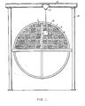
- Fig. 1 is a pictorial representation of a tube sheet showing a typical welding pattern for continuously welding a plurality of tubes disposed in a plurality of rows to a tube sheet;
- Fig. 2 is a perspective view of apparatus utilized to continuously weld a plurality of tubes in a plurality of rows to a tube sheet;
- Fig. 3 shows the orthographic movement of a torch to discrete locations about the center of a tube; and
- Fig. 4 through 6 show various continuous weld paths for continuously welding a plurality of tubes in a plurality of rows to a tube sheet.
- Referring now to the drawings in detail and in particular to Fig. 1 there is shown a tube sheet 1 of a heat exchanger 3 with a plurality of tubes 5 disposed therein in rows and being seal welded to the tube sheet by a continuous weld 7 which encompasses a plurality of tubes in a plurality of rows. A hoist 9 is disposed above the heat exchanger and rolls on a beam 11 supported by the
columns 12. The hoist 9 supportscontinuous welding apparatus 13 for continuously welding a portion of a plurality of rows of tubes. - As shown in Figure 2 the
continuous welding apparatus 13 comprises abase 15 and means 17 for attaching thebase 15 to the tube sheet 1. Themeans 17 for attaching thebase 15 to the tube sheet 1 comprises anelastomer sleeve 19 which is compressed axially by a pneumatic orhydraulic cylinder 21 to expand theelastomer sleeve 19 into radial engagement with a tube or tube hole. While only one such attaching means is shown, another such means is disposed diagonally opposite the one shown but cannot be seen in the drawing. - A
carriage 23 is slidably disposed on thebase 15 so as to move rectilinearly in Y direction and a steppingmotor drive 25 rotates a screw (not shown), which engages a split nut (not shown) which can be made to engage and disengage the screw by moving alever 27 disposed on the carriage allowing free or controlled movement of thecarriage 23 in the Y direction depending on whether or not the split nut engages the screw. Alinear encoder 29 is utilized to signal the Y position of thecarriage 23. - Slidably disposed on the
carriage 23 is a crossfeedframe 31 which is so disposed thereon to move rectilinearly in the X direction. A stepping motor drive 33 rotates ascrew 35 which engages a split nut (not shown), which can be made to engage and disengage thescrew 35 by moving thelever 37 allowing free or controlled movement of thecross-feed frame 31. Alinear encoder 39 is utilized to signal the X position of the cross-feed frame at all times. - A torch and probe holder 41 is slidably disposed on the
cross-feed 31 so as to move rectilinearly in the Z direction. By operating alever 45 the torch and probe holder 41 may move freely in the Z direction or drive means 43 may move the torch or probe in the Z direction. Anencoder 37 signals the Z position of the torch and probe holder 41 at all times. Control of the Z axis provides feedback for hole size during probing and voltage control during welding. - The torch and probe holder 41 is shown with a
welding torch 49 disposed therein. The probe is similar to the torth in that it has a tapered or conical-shaped end which fits into the tubes. - Disposed on the
cross-feed rack 31 is aswitch 51 which is activated to send a signal when the probe is centered in a tube. - A
welding machine 61 supplies power and shielding gas to thetorch 49. The torch is preferably an inert gas tungsten arc torch. - A
controller 63, such as Texas Instrument Program Master 550, responds to the positions of the tubes and drives thestep motors 25 and 33 to cause the welding torch to follow predetermined welding paths similar to those shown in Figures 3 through 5. An automatic voltage control moves the torch toward and away from the tube sheet to maintain a constant voltage on the arc utilizing the drive means 43. The controller can also respond to the depth that the probe fits into the tube to vary the path around the individual tubes to compensate for differences in diameter therebetween. - The method for continuously welding at least a portion of multiple rows of tubes to a tube sheet utilizing
weld apparatus 13 which can automatically drive thewelding torch 49 to any X and Y position encompassing a portion of multiple rows of tubes comprises the steps of: - expanding the tubes into holding engagement with the tube sheet;
- attaching the
welding apparatus 13 to the tube sheet 1 by inserting theelastomer sleeves 19 into tubes attached to the tube sheet and axially compressing theelastomer sleeves 19 into holding engagement with the tubes; - releasing the
levers torch 49 with a probe having a conical-shaped end; - placing the conical-shaped end or tip of the probe into each tube to be welding to the tube sheet;
- sending a signal to the
controller 63 when the probe is centered within a tube to be welded by depressing theswitch 51; - recording the X, Y and Z positions of the probe upon receiving the signal that the probe is centered within a tube;
- repeating the above two steps for each tube to be welded to the tube sheet;
- remove the probe tip from the torch and replacing the probe with a shielding gas cup welding;
- operating the
levers automatic drives 25, 33 and 43, respectively. - automatically or manually bringing the torch to a predetermined starting position and initiating an arc between the torch and the tube sheet;
- forming a continuous weld following a predetermined path which includes a predetermined number of locations P1 to P40 disposed about the periphery of each tube having its X and Y position recorded, the locations P 1 to P40 need not be concentric with the center of the tubes and they need not be on a circular path, but may be on any path which produces the best weld characteristics (for example since the tube sheet is vertically disposed there is a slight tendency for the weld metal to sag downwardly due to the force of gravity and the weld puddle thus is intentionally moved upwardly slightly to compensate for the downward sagging).
- The depth that the probe enters the tube sheet is an indication of the diameter of the hole and tube and can be utilized to change the diameter of the locations P 1 to P40 as the torch goes to these various positions about each tube.
- Since the exact X, Y positions of each tube to be welded is recorded the predetermined path includes the tubes T1 through T20 and can compensate for tubes having unusual pitch length as shown in Figure 4 where the tubes T4, T9 and T15 are irregularly spaced. As shown in Figure 5 the predetermined path may include irregular spaces where tubes are left out to provide for stay rods and blowdown piping as shown in Figure 5 between tubes T6 and T7 and between tubes T15 and T16. The predetermined path can also include row length adjustments necessitated by the location of the walls of the vessel as shown in Figure 6.
- The welding sequence is automatically determined and does not necessarily follows the probing hole sequence, but rather the most efficient serpentine path of holes probed.
- The continuous tube welding method and apparatus hereinbefore described is ideally suited for fusion welding, in particular where large numbers of tubes are available for welding and the reduced weld cycle time increases weld efficiency.
Claims (3)
Applications Claiming Priority (2)
| Application Number | Priority Date | Filing Date | Title |
|---|---|---|---|
| US16799580A | 1980-07-14 | 1980-07-14 | |
| US167995 | 1980-07-14 |
Publications (2)
| Publication Number | Publication Date |
|---|---|
| EP0043915A1 EP0043915A1 (en) | 1982-01-20 |
| EP0043915B1 true EP0043915B1 (en) | 1984-09-12 |
Family
ID=22609652
Family Applications (1)
| Application Number | Title | Priority Date | Filing Date |
|---|---|---|---|
| EP81104493A Expired EP0043915B1 (en) | 1980-07-14 | 1981-06-11 | Method for continuously welding a plurality of tubes disposed in multiple rows to a tube sheet |
Country Status (6)
| Country | Link |
|---|---|
| EP (1) | EP0043915B1 (en) |
| JP (1) | JPS5747597A (en) |
| KR (1) | KR850000146B1 (en) |
| DE (1) | DE3165991D1 (en) |
| ES (1) | ES503918A0 (en) |
| YU (1) | YU41783B (en) |
Families Citing this family (3)
| Publication number | Priority date | Publication date | Assignee | Title |
|---|---|---|---|---|
| JPS59218279A (en) * | 1983-05-24 | 1984-12-08 | Ube Ind Ltd | Automatic tube sheet welding method using numerical control |
| US4965431A (en) * | 1989-08-21 | 1990-10-23 | Blackstone Corporation | Sweep welding method and apparatus therefor |
| JP6153060B2 (en) * | 2013-03-30 | 2017-06-28 | 株式会社ノーリツ | Heat exchanger and manufacturing method thereof |
Family Cites Families (1)
| Publication number | Priority date | Publication date | Assignee | Title |
|---|---|---|---|---|
| US4161646A (en) * | 1977-07-08 | 1979-07-17 | Owens-Corning Fiberglas Corporation | Method of welding tubular members |
-
1981
- 1981-06-11 DE DE8181104493T patent/DE3165991D1/en not_active Expired
- 1981-06-11 EP EP81104493A patent/EP0043915B1/en not_active Expired
- 1981-06-12 YU YU1479/81A patent/YU41783B/en unknown
- 1981-07-10 JP JP56107215A patent/JPS5747597A/en active Pending
- 1981-07-13 ES ES503918A patent/ES503918A0/en active Granted
- 1981-07-14 KR KR1019810002558A patent/KR850000146B1/en not_active Expired
Also Published As
| Publication number | Publication date |
|---|---|
| ES8300546A1 (en) | 1982-11-01 |
| KR850000146B1 (en) | 1985-02-28 |
| KR830005954A (en) | 1983-09-14 |
| DE3165991D1 (en) | 1984-10-18 |
| YU147981A (en) | 1984-02-29 |
| EP0043915A1 (en) | 1982-01-20 |
| JPS5747597A (en) | 1982-03-18 |
| ES503918A0 (en) | 1982-11-01 |
| YU41783B (en) | 1987-12-31 |
Similar Documents
| Publication | Publication Date | Title |
|---|---|---|
| US4162383A (en) | Oxy-arc apparatus for cutting inside a pipe | |
| KR910000516B1 (en) | Electric discharge processing method and electric discharge processing machine | |
| US9208910B2 (en) | Installation for welding nuclear fuel assembly skeletons, and corresponding methods of programming, of skeleton welding, and of making a fuel assembly | |
| US4952773A (en) | Automatic arc-welding machine operating with rod electrodes and a preferred application thereof | |
| JPH0575516B2 (en) | ||
| EP3569348B1 (en) | Automatic replacement device and method for gas shielded welding tungsten electrode of robot welding system | |
| JPH01205937A (en) | Device for cutting tubularpiece wall through electric discharge machining | |
| US5251243A (en) | Automatic fuel assembly loader | |
| EP0043915A1 (en) | Method for continuously welding a plurality of tubes disposed in multiple rows to a tube sheet | |
| US4359621A (en) | Method for continuously welding a plurality of tubes disposed in multiple rows to a tube sheet | |
| JP2001018066A (en) | Welding apparatus | |
| KR20190083961A (en) | Overlay welding apparatus of individual control type of plural welding units | |
| CN218533132U (en) | Multi-axis welding device | |
| JPS617035A (en) | Apparatus for producing panel | |
| JP7603278B2 (en) | How to weld steel pipe columns | |
| US4271471A (en) | Method of operating a remotely controlled tool positioning table | |
| EP0353351A1 (en) | Panelizing machine and method for use | |
| KR100456884B1 (en) | Welding Point auto adjusting device in welding robert | |
| US3824663A (en) | Method of welding a tube to a tube sheet | |
| JPH0116213B2 (en) | ||
| JPS60145287A (en) | Automatic welding device for pipe material and tubular parts | |
| US3783232A (en) | Apparatus for the manufacture of hollow rod elements | |
| JP2006075870A (en) | Axis alignment mechanism and automatic pipe end welding equipment | |
| JPH05142386A (en) | Method and apparatus for drawing deformed heating rod out of casing of compressor in pressurized water reactor | |
| KR101988822B1 (en) | Contact tip changer for welding |
Legal Events
| Date | Code | Title | Description |
|---|---|---|---|
| PUAI | Public reference made under article 153(3) epc to a published international application that has entered the european phase |
Free format text: ORIGINAL CODE: 0009012 |
|
| AK | Designated contracting states |
Designated state(s): BE DE FR GB IT SE |
|
| 17P | Request for examination filed |
Effective date: 19820717 |
|
| ITF | It: translation for a ep patent filed | ||
| GRAA | (expected) grant |
Free format text: ORIGINAL CODE: 0009210 |
|
| AK | Designated contracting states |
Designated state(s): BE DE FR GB IT SE |
|
| REF | Corresponds to: |
Ref document number: 3165991 Country of ref document: DE Date of ref document: 19841018 |
|
| ET | Fr: translation filed | ||
| PLBE | No opposition filed within time limit |
Free format text: ORIGINAL CODE: 0009261 |
|
| STAA | Information on the status of an ep patent application or granted ep patent |
Free format text: STATUS: NO OPPOSITION FILED WITHIN TIME LIMIT |
|
| 26N | No opposition filed | ||
| PGFP | Annual fee paid to national office [announced via postgrant information from national office to epo] |
Ref country code: FR Payment date: 19890321 Year of fee payment: 9 |
|
| PGFP | Annual fee paid to national office [announced via postgrant information from national office to epo] |
Ref country code: SE Payment date: 19890328 Year of fee payment: 9 |
|
| PGFP | Annual fee paid to national office [announced via postgrant information from national office to epo] |
Ref country code: GB Payment date: 19890331 Year of fee payment: 9 |
|
| PGFP | Annual fee paid to national office [announced via postgrant information from national office to epo] |
Ref country code: BE Payment date: 19890517 Year of fee payment: 9 |
|
| ITTA | It: last paid annual fee | ||
| PGFP | Annual fee paid to national office [announced via postgrant information from national office to epo] |
Ref country code: DE Payment date: 19890630 Year of fee payment: 9 |
|
| PG25 | Lapsed in a contracting state [announced via postgrant information from national office to epo] |
Ref country code: GB Effective date: 19900611 |
|
| PG25 | Lapsed in a contracting state [announced via postgrant information from national office to epo] |
Ref country code: SE Effective date: 19900612 |
|
| PG25 | Lapsed in a contracting state [announced via postgrant information from national office to epo] |
Ref country code: BE Effective date: 19900630 |
|
| BERE | Be: lapsed |
Owner name: WESTINGHOUSE ELECTRIC CORP. Effective date: 19900630 |
|
| GBPC | Gb: european patent ceased through non-payment of renewal fee | ||
| PG25 | Lapsed in a contracting state [announced via postgrant information from national office to epo] |
Ref country code: FR Effective date: 19910228 |
|
| PG25 | Lapsed in a contracting state [announced via postgrant information from national office to epo] |
Ref country code: DE Effective date: 19910301 |
|
| REG | Reference to a national code |
Ref country code: FR Ref legal event code: ST |
|
| EUG | Se: european patent has lapsed |
Ref document number: 81104493.2 Effective date: 19910206 |