EP0042911A2 - Mounting with a single hydraulic damping chamber - Google Patents
Mounting with a single hydraulic damping chamber Download PDFInfo
- Publication number
- EP0042911A2 EP0042911A2 EP81102000A EP81102000A EP0042911A2 EP 0042911 A2 EP0042911 A2 EP 0042911A2 EP 81102000 A EP81102000 A EP 81102000A EP 81102000 A EP81102000 A EP 81102000A EP 0042911 A2 EP0042911 A2 EP 0042911A2
- Authority
- EP
- European Patent Office
- Prior art keywords
- end wall
- chamber
- wall
- pot
- bearing according
- Prior art date
- Legal status (The legal status is an assumption and is not a legal conclusion. Google has not performed a legal analysis and makes no representation as to the accuracy of the status listed.)
- Granted
Links
Images
Classifications
-
- F—MECHANICAL ENGINEERING; LIGHTING; HEATING; WEAPONS; BLASTING
- F16—ENGINEERING ELEMENTS AND UNITS; GENERAL MEASURES FOR PRODUCING AND MAINTAINING EFFECTIVE FUNCTIONING OF MACHINES OR INSTALLATIONS; THERMAL INSULATION IN GENERAL
- F16F—SPRINGS; SHOCK-ABSORBERS; MEANS FOR DAMPING VIBRATION
- F16F13/00—Units comprising springs of the non-fluid type as well as vibration-dampers, shock-absorbers, or fluid springs
- F16F13/04—Units comprising springs of the non-fluid type as well as vibration-dampers, shock-absorbers, or fluid springs comprising both a plastics spring and a damper, e.g. a friction damper
- F16F13/06—Units comprising springs of the non-fluid type as well as vibration-dampers, shock-absorbers, or fluid springs comprising both a plastics spring and a damper, e.g. a friction damper the damper being a fluid damper, e.g. the plastics spring not forming a part of the wall of the fluid chamber of the damper
- F16F13/08—Units comprising springs of the non-fluid type as well as vibration-dampers, shock-absorbers, or fluid springs comprising both a plastics spring and a damper, e.g. a friction damper the damper being a fluid damper, e.g. the plastics spring not forming a part of the wall of the fluid chamber of the damper the plastics spring forming at least a part of the wall of the fluid chamber of the damper
- F16F13/18—Units comprising springs of the non-fluid type as well as vibration-dampers, shock-absorbers, or fluid springs comprising both a plastics spring and a damper, e.g. a friction damper the damper being a fluid damper, e.g. the plastics spring not forming a part of the wall of the fluid chamber of the damper the plastics spring forming at least a part of the wall of the fluid chamber of the damper characterised by the location or the shape of the equilibration chamber, e.g. the equilibration chamber, surrounding the plastics spring or being annular
Definitions
- the invention has for its object to improve the single-chamber bearing described in EP-OS 00 14 742 and to arrange the compensation space so that its proper function cannot be impaired by external influences.
- the manufacture of the single-chamber bearing should be simplified.
- the metal end wall is cup-shaped and the compensation space is arranged within this end wall.
- This end wall which takes on this shape without additional effort, protects the compensation space from damage.
- the pot-shaped end wall is curved inwards enables easy installation of the compensation space from the outside.
- An additional closure of the free end of the pot-shaped end wall by a cover plate results in a complete encapsulation of the compensation space.
- the cover plate carries a mounting pin for the bearing. This not only enables simple manufacture, but also easy attachment of the single-chamber bearing.
- the throttle point is formed by a nipple with a throttle opening which is inserted centrally into the pot-shaped end wall. This allows the throttle point to be separated from the Hydraulically damping single chamber noise
- the invention relates to a hydraulically damping single-chamber bearing, in particular motor bearings for motor vehicles, consisting of a first, diaphragm-like, sealingly connected to a metallic abutment and oscillating with axial play defined on both sides, a second, metallic end wall and one between the two end walls extending, rubber-elastic peripheral wall limited, filled with damping liquid chamber and a separate, at least part of the damping liquid of the chamber pressure-absorbing, elastically deformable compensation space connected to the chamber via a throttle point in the metallic end wall.
- the elastically deformable compensation space which absorbs the damping liquid of the chamber without pressure, is arranged outside the actual bearing and is externally through a tubular, with its ends on the metallic abutment and the metallic end wall limited connected bellows.
- the bellows which has a relatively thin wall thickness, will be damaged and thus become unusable for the single-chamber bearing to function properly.
- an oscillation of the central region of the end wall 8 provided with a reinforcement is ensured in the axial direction in a predetermined size.
- the pot-like end wall 2 is closed at its outer end by a cover plate 13, which also carries a fastening pin 14.
- a balloon-like bellows 16 made of elastic material is inserted, which projects with its open end into a central opening 17 of the end wall 2.
- a nipple 18 made of plastic is inserted into the open end of the bellows 16, via which the open end of the bellows 16 is sealingly held in the opening 17 of the end wall 2.
- the nipple 18 has a throttle opening 19, via which the chamber 20 delimited by the end wall 2, the end wall 8 and the peripheral wall 4 is in flow connection with a compensation chamber 21 enclosed by the bellows 16.
- Both the chamber 20 and the compensation chamber 21 are filled with damping liquid without pressure.
- the compensation chamber 21 absorbs the damping liquid which thereby flows out through the throttle opening 19 without pressure and deforms the bellows 16. So that there is no resistance to this deformation in the capsule 15, the cover plate 13 is equipped with an opening 22 for venting and venting the capsule 15.
- the single-chamber bearing 1 shown in the drawing is effective both in the illustrated position and in the inclined position and in the position rotated by 180 °.
- End wall are manufactured and can be inserted into the end wall with little effort using a seal. With a nipple made of plastic, the seal can be saved.
- the compensation space is preferably formed by a balloon-like bellows. This ensures that the compensation space only has to be connected to the end wall on an annular surface. It is also possible to hold the bellows forming the compensation space directly in the end wall by means of the nipple having the throttle opening. This simplifies the mounting and assembly effort.
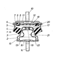
- a single-chamber bearing 1 for the engine of a motor vehicle is shown in section, which consists of a pot-like, metallic end wall 2 with a conical connecting surface 3.
- a rubber-elastic, spring-acting peripheral wall 4 is vulcanized, which is connected by its other ring surface by vulcanization to an annular abutment 5.
- a thin layer of the peripheral wall 4 extends into an annular flange 6 and here fulfills the function of a seal.
- the flange 6 receives on the one hand the outer ring 7 of a membrane-like end wall 8 and on the other hand a cover plate 9 which carries a fastening pin 10 and has an opening 11 for ventilation of the space 12 formed between the end wall 8 and cover plate 9.
- the membrane-like end wall 8 is designed so that in the connection area of the elastic Instead of the fastening pin 10, a circumferential fastening flange or a fastening lug can be connected to the abutment 5.
Abstract
Description
Der Erfindung liegt die Aufgabe zugrunde, das in der EP-OS 00 14 742 beschriebene Einkammerlager zu verbessern und den Ausgleichsraum so anzuordnen, daß seine einwandfreie Funktion durch äußere Einflüsse nicht beeinträchtigt werden kann. Zusätzlich soll die Herstellung des Einkammerlagers vereinfacht werden.The invention has for its object to improve the single-chamber bearing described in EP-OS 00 14 742 and to arrange the compensation space so that its proper function cannot be impaired by external influences. In addition, the manufacture of the single-chamber bearing should be simplified.
Zur Lösung dieser Aufgabe wird bei dem eingangs beschriebenen Einkammerlager vorgeschlagen, daß die metallische Stirnwand topfartig ausgebildet und der Ausgleichsraum innerhalb dieser Stirnwand angeordnet ist. Diese Stirnwand, die ohne zusätzlichen Aufwand diese Form erhält, schützt den Ausgleichsraum vor Beschädigungen.To solve this problem, it is proposed in the single-chamber bearing described at the outset that the metal end wall is cup-shaped and the compensation space is arranged within this end wall. This end wall, which takes on this shape without additional effort, protects the compensation space from damage.
Dadurch, daß die topfartig ausgebildete Stirnwand nach innen gewölbt ist, wird eine leichte Montage des Ausgleichsraumes von außen ermöglicht. Ein zusätzliches Verschließen des freien Endes der topfartig ausgebildeten Stirnwand durch eine Deckplatte ergibt eine vollständige Kapselung des Ausgleichsraumes. Vorzugsweise trägt die Deckplatte einen Befestigungsstift für das Lager. Dies ermöglicht nicht nur eine einfache Herstellung, sondern auch eine leichte Anbringung des Einkammerlagers.The fact that the pot-shaped end wall is curved inwards enables easy installation of the compensation space from the outside. An additional closure of the free end of the pot-shaped end wall by a cover plate results in a complete encapsulation of the compensation space. Preferably, the cover plate carries a mounting pin for the bearing. This not only enables simple manufacture, but also easy attachment of the single-chamber bearing.
Gemäß einer vorteilhaften Ausbildung der Erfindung ist die Drosselstelle durch einen zentrisch in die topfartig ausgebildete Stirnwand eingesetzten Nippel mit einer Drosselöffnung gebildet. Dadurch kann die Drosselstelle in einfacher Weise getrennt von der Hydraulisch dämpfendes EinkammerlaaerAccording to an advantageous embodiment of the invention, the throttle point is formed by a nipple with a throttle opening which is inserted centrally into the pot-shaped end wall. This allows the throttle point to be separated from the Hydraulically damping single chamber noise
Die Erfindung bezieht sich auf ein hydraulisch dämpfendes Einkammerlager, insbesondere Motorlager für Kraftfahrzeuge, bestehend aus einer von einer ersten, membranartigen, dichtend an einem metallischen Widerlager angeschlossenen und mit axialem, beidseitig definiertem Spiel oszillierenden Stirnwand, einer zweiten, metallischen Stirnwand und einer sich zwischen den beiden Stirnwänden erstreckenden,gummi-elastischen Umfangswand begrenzten, mit Dämpfungsflüssigkeit gefüllten Kammer und einem getrennten, über eine in der metallischen Stirnwand befindliche Drosselstelle mit der Kammer verbundenen, zumindest einen Teil der Dämpfungsflüssigkeit der Kammer drucklos aufnehmenden, elastisch verformbaren Ausgleichsraum.The invention relates to a hydraulically damping single-chamber bearing, in particular motor bearings for motor vehicles, consisting of a first, diaphragm-like, sealingly connected to a metallic abutment and oscillating with axial play defined on both sides, a second, metallic end wall and one between the two end walls extending, rubber-elastic peripheral wall limited, filled with damping liquid chamber and a separate, at least part of the damping liquid of the chamber pressure-absorbing, elastically deformable compensation space connected to the chamber via a throttle point in the metallic end wall.
Bei einem in der EP-OS 00 14 742 beschriebenen Einkammerlager der vorerwähnten Gattung ist der die Dämpfungsflüssigkeit der Kammer drucklos aufnehmende, elastisch verformbare Ausgleichsraum außerhalb des eigentlichen Lagers angeordnet und wird nach außen durch einen rohrförmigen, mit seinen Enden am metallischen Widerlager und der metallischen Stirnwand dichtend angeschlossenen Faltenbalg begrenzt. Dadurch besteht die Gefahr, daß der eine verhältnismäßig dünne Wandstärke aufweisende Faltenbalg beschädigt und damit für eine einwandfreie Funktion des Einkammerlagers unbrauchbar wird. Darüberhinaus Teiles der Stirnwand 8 mit dem eingespannten Ring 7 eine Oszillierbarkeit des mit einer Verstärkung versehenen mittleren Bereiches der Stirnwand 8 in axialer Richtung in vorbestimmter Größe gewährleistet ist.In a single-chamber bearing of the aforementioned type described in EP-OS 00 14 742, the elastically deformable compensation space, which absorbs the damping liquid of the chamber without pressure, is arranged outside the actual bearing and is externally through a tubular, with its ends on the metallic abutment and the metallic end wall limited connected bellows. As a result, there is a risk that the bellows, which has a relatively thin wall thickness, will be damaged and thus become unusable for the single-chamber bearing to function properly. Furthermore Part of the
Die topfartige Stirnwand 2 ist an ihrem äußeren Ende durch eine Deckplatte 13 geschlossen, die ebenfalls einen Befestigungsstift 14 trägt. In die durch die Stirnwand 2 und die Deckplatte 13 gebildete Kapsel 15 ist ein ballonartiger Faltenbalg 16 aus elastischem Werkstoff eingesetzt, der mit seinem offenen Ende in eine zentrische Öffnung 17 der Stirnwand 2 ragt. In das offene Ende des Faltenbalges 16 ist ein Nippel 18 aus Kunststoff eingesteckt, über den das offene Ende des Faltenbalges 16 dichtend in der Öffnung 17 der Stirnwand 2 gehalten ist. Der Nippel 18 besitzt eine Drosselöffnung 19, über die die von der Stirnwand 2, der Stirnwand 8 und der Umfangswand 4 begrenzte Kammer 20 mit einem von dem Faltenbalg 16 umschlossenen Ausgleichsraum 21 in Strömungsverbindung steht.The pot-
Sowohl die Kammer 20 als auch der Ausgleichsraum 21 sind drucklos mit Dämpfungsflüssigkeit gefüllt. Bei einer Verkleinerung der Kammer 20 durch von außen einwirkende Kräfte nimmt der Ausgleichsraum 21 die dadurch über die Drosselöffnung 19 ausströmende Dämpfungsflüssigkeit drucklos unter Verformung des Faltenbalges 16 auf. Damit dieser Verformung in der Kapsel 15 kein Widerstand entgegensteht, ist die Deckplatte 13 mit einer Öffnung 22 zur Ent- und Belüftung der Kapsel 15 ausgerüstet.Both the
Das in der Zeichnung dargestellte Einkammerlager 1 ist sowohl in der dargestellten als auch in geneigter als auch in um 180° gedrehter Lage wirksam.The single-chamber bearing 1 shown in the drawing is effective both in the illustrated position and in the inclined position and in the position rotated by 180 °.
Stirnwand gefertigt werden und ist ohne großen Aufwand mittels einer Dichtung in die Stirnwand einsetzbar. Bei einem Nippel aus Kunststoff kann die Dichtung eingespart werden.End wall are manufactured and can be inserted into the end wall with little effort using a seal. With a nipple made of plastic, the seal can be saved.
Vorzugsweise ist der Ausgleichsraum durch einen ballonartigen Faltenbalg gebildet. Hierdurch wird erreicht, daß der Ausgleichsraum nur an einer ringförmigen Fläche mit der Stirnwand verbunden werden muß. Dabei ist es auch möglich,-.den den Ausgleichsraum bildenden Faltenbalg direkt mittels des die Drosselöffnung aufweisenden Nippels in der Stirnwand zu halten. Dies vereinfacht den Befestigungs- und Montageaufwand.The compensation space is preferably formed by a balloon-like bellows. This ensures that the compensation space only has to be connected to the end wall on an annular surface. It is also possible to hold the bellows forming the compensation space directly in the end wall by means of the nipple having the throttle opening. This simplifies the mounting and assembly effort.
Der Gegenstand der Erfindung wird nachfolgend anhand eines in einer Zeichnung dargestellten Ausführungsbeispieles näher erläutert. In dieser Zeichnung.ist ein Einkammerlager 1 für den Motor eines Kraftfahrzeuges im schnitt gezeigt, das aus einer topfartigen, metallischen Stirnwand 2 mit einer kegeligen Anschlußfläche 3 besteht. An der äußeren Seite dieser kegeligen Anschlußfläche 3 ist eine gummielastische, als Feder wirkende Umfangswand 4 anvulkanisiert, die über ihre andere Ringfläche durch Vulkanisation an ein ringförmiges Widerlager 5 angeschlossen ist. Eine dünne Schicht der Umfangswand 4 erstreckt sich bis in eine ringförmige Umbördelung 6 und erfüllt hier die Funktion einer Dichtung.The object of the invention is explained in more detail below with reference to an embodiment shown in a drawing. In this drawing, a single-chamber bearing 1 for the engine of a motor vehicle is shown in section, which consists of a pot-like,
Die Umbördelung 6 nimmt einerseits den äußeren Ring 7 einer membranartigen Stirnwand 8 und andererseits eine Deckplatte 9 auf, die einen Befestigungsstift 10 trägt und eine Öffnung 11 zur Belüftung des zwischen Stirnwand 8 und Deckplatte 9 gebildeten Raumes 12 besitzt. Die membranartige Stirnwand 8 ist so ausgebildet, daß im Verbindungsbereich des elastischen Anstelle des Befestigungsstiftes 10 kann am Widerlager 5 ein umlaufender Befestigungsflansch oder eine Befestigungsnase angeschlossen sein.The
- 1 Einkammerlager1 single chamber bearing
- 2 Stirnwand2 front wall
- 3 Anschlußfläche3 pad
- 4 Umfangswand4 peripheral wall
- 5 Widerlager5 abutments
- 6 Umbördelung6 flanging
- 7 Ring7 ring
- 8 Stirnwand8 end wall
- 9 Deckplatte9 cover plate
- 10 Befestigungsstift10 fastening pin
- 11 Öffnung11 opening
- 12 Raumes12 room
- 13 Deckplatte13 cover plate
- 14 Befestigungsstift14 mounting pin
- 15 Kapsel15 capsules
- 16 Faltenbalg16 bellows
- 17 Öffnung17 opening
- 18 Nippel18 nipples
- 19 Drosselöffnung19 throttle opening
- 20 Kammer20 chamber
- 21 Ausgleichsraum21 compensation room
- 22 Öffnung22 opening
Claims (8)
dadurch gekennzeichnet,
daß die metallische Stirnwand (2) topfartig ausgebildet und der Ausgleichsraum (21) innerhalb dieser Stirnwand (2) angeordnet ist.1: Hydraulically damping single-chamber bearing, in particular engine mounting for motor vehicles, consisting of a front wall, connected by a first, membrane-like, sealingly connected to a metallic abutment and oscillating with axial play defined on both sides, a second, metal front wall and a wall extending between the two front walls, rubber-elastic peripheral wall limited, filled with damping liquid and a separate, elastically deformable compensation space connected to the chamber via a throttle point located in the metal end wall and absorbing at least part of the damping liquid of the chamber without pressure,
characterized,
that the metallic end wall (2) is pot-shaped and the compensation space (21) is arranged within this end wall (2).
dadurch gekennzeichnet,
daß die topfartig ausgebildete Stirnwand (2) nach innen gewölbt ist.2. single chamber bearing according to claim 1,
characterized,
that the pot-shaped end wall (2) is curved inwards.
dadurch gekennzeichnet,
daß die topfartig ausgebildete Stirnwand (2) an ihrem äußeren Ende durch eine Deckplatte (13) verschlossen ist.3. single chamber bearing according to claim 1 or 2,
characterized,
that the pot-shaped end wall (2) is closed at its outer end by a cover plate (13).
dadurch gekennzeichnet,
daß die Deckplatte (13) einen Befestigungsstift (14) für das Lager (1) trägt.4. single chamber bearing according to claim 3,
characterized,
that the cover plate (13) carries a fastening pin (14) for the bearing (1).
dadurch gekennzeichnet,
daß die Drosselstelle durch einen zentrisch in die topfartig ausgebildete Stirnwand (2) eingesetzten Nippel (18) mit einer Drosselöffnung (19) gebildet ist.Single chamber bearing according to at least one of claims 1-4,
characterized,
that the throttle point is formed by a nipple (18) inserted centrally into the pot-shaped end wall (2) with a throttle opening (19).
dadurch gekennzeichnet,
daß der Nippel (18) aus Kunststoff besteht.6. single chamber bearing according to claim 6,
characterized,
that the nipple (18) is made of plastic.
dadurch gekennzeichnet,
daß der Ausgleichsraum (21) durch einen ballonartigen Faltenbalg (16) gebildet ist.7. Single chamber bearing according to at least one of the claims. 1-6,
characterized,
that the compensation space (21) is formed by a balloon-like bellows (16).
dadurch gekennzeichnet,
daß der Faltenbalg (16) mittels des Nippels (18) in der Stirnwand (2) gehalten ist.8. single chamber bearing according to claim 7,
characterized,
that the bellows (16) is held in the end wall (2) by means of the nipple (18).
Applications Claiming Priority (2)
| Application Number | Priority Date | Filing Date | Title |
|---|---|---|---|
| DE3024092 | 1980-06-27 | ||
| DE19803024092 DE3024092C2 (en) | 1980-06-27 | 1980-06-27 | Hydraulically damping single-chamber bearing |
Publications (3)
| Publication Number | Publication Date |
|---|---|
| EP0042911A2 true EP0042911A2 (en) | 1982-01-06 |
| EP0042911A3 EP0042911A3 (en) | 1982-04-21 |
| EP0042911B1 EP0042911B1 (en) | 1985-09-18 |
Family
ID=6105594
Family Applications (1)
| Application Number | Title | Priority Date | Filing Date |
|---|---|---|---|
| EP81102000A Expired EP0042911B1 (en) | 1980-06-27 | 1981-03-18 | Mounting with a single hydraulic damping chamber |
Country Status (2)
| Country | Link |
|---|---|
| EP (1) | EP0042911B1 (en) |
| DE (1) | DE3024092C2 (en) |
Cited By (7)
| Publication number | Priority date | Publication date | Assignee | Title |
|---|---|---|---|---|
| EP0098128A1 (en) * | 1982-06-25 | 1984-01-11 | Dunlop Limited | Improvements in or relating to resilient mountings |
| EP0119796A2 (en) * | 1983-03-09 | 1984-09-26 | Bridgestone Tire Company Limited | Vibration damping device |
| FR2555273A1 (en) * | 1983-11-22 | 1985-05-24 | Hutchinson Sa | Improvements made to hydraulic anti-vibration supports |
| EP0143115A1 (en) * | 1983-11-28 | 1985-06-05 | TOYO TIRE & RUBBER CO., LTD . | Vibration-absorbing mount with hydraulic damping, e.g. for engines |
| FR2558229A1 (en) * | 1984-01-17 | 1985-07-19 | Gomma Antivibranti Applic | ENGINE SUPPORT |
| GB2168778A (en) * | 1984-11-14 | 1986-06-25 | Continental Gummi Werke Ag | A hydraulically damped resilient mounting |
| GB2339259A (en) * | 1998-07-07 | 2000-01-19 | Draftex Ind Ltd | Anti-vibration mount |
Families Citing this family (4)
| Publication number | Priority date | Publication date | Assignee | Title |
|---|---|---|---|---|
| DE3142673A1 (en) * | 1981-10-28 | 1983-05-05 | Continental Gummi-Werke Ag, 3000 Hannover | Elastic mount, in particular for the engine in motor vehicles |
| DE3244296A1 (en) * | 1982-11-30 | 1984-05-30 | Metzeler Kautschuk GmbH, 8000 München | TWO-CHAMBER ENGINE MOUNT WITH HYDRAULIC DAMPING |
| DE3246587C2 (en) * | 1982-12-16 | 1986-09-25 | Boge Gmbh, 5208 Eitorf | Hydraulically damping rubber mount |
| CN114952714B (en) * | 2021-02-26 | 2023-06-02 | 中国航发商用航空发动机有限责任公司 | Rotor disc bolt installation tool and operation method thereof |
Citations (7)
| Publication number | Priority date | Publication date | Assignee | Title |
|---|---|---|---|---|
| FR1178262A (en) * | 1956-07-31 | 1959-05-05 | Metalastik Ltd | Improvement in anti-vibration mounts |
| US3137466A (en) * | 1962-05-23 | 1964-06-16 | Gen Motors Corp | Engine mount |
| US4159091A (en) * | 1976-06-30 | 1979-06-26 | Automobiles Peugeot | Damper device, in particular for the suspension of an engine |
| DE2941118A1 (en) * | 1978-10-13 | 1980-06-04 | Gould Inc | LIQUID AND SPRING DAMPED DEVICE |
| EP0014742A1 (en) * | 1979-02-19 | 1980-09-03 | Boge GmbH | Hydraulic shock absorbing single-compartment mounting |
| DE2932478A1 (en) * | 1979-08-10 | 1981-02-26 | Freudenberg Carl Fa | HYDRO BEARING |
| FR2475172A1 (en) * | 1980-01-31 | 1981-08-07 | Bridgestone Tire Co Ltd | RUBBER ANTI-VIBRATION INSULATOR |
Family Cites Families (2)
| Publication number | Priority date | Publication date | Assignee | Title |
|---|---|---|---|---|
| DE2227139C3 (en) * | 1972-06-03 | 1976-01-02 | Fried. Krupp Gmbh, 4300 Essen | Shock-absorbing putter, especially elevator buffers |
| DE7636318U1 (en) * | 1976-11-18 | 1979-02-01 | Phoenix Ag, 2100 Hamburg | Elastic bearing |
-
1980
- 1980-06-27 DE DE19803024092 patent/DE3024092C2/en not_active Expired
-
1981
- 1981-03-18 EP EP81102000A patent/EP0042911B1/en not_active Expired
Patent Citations (8)
| Publication number | Priority date | Publication date | Assignee | Title |
|---|---|---|---|---|
| FR1178262A (en) * | 1956-07-31 | 1959-05-05 | Metalastik Ltd | Improvement in anti-vibration mounts |
| US3137466A (en) * | 1962-05-23 | 1964-06-16 | Gen Motors Corp | Engine mount |
| US4159091A (en) * | 1976-06-30 | 1979-06-26 | Automobiles Peugeot | Damper device, in particular for the suspension of an engine |
| DE2941118A1 (en) * | 1978-10-13 | 1980-06-04 | Gould Inc | LIQUID AND SPRING DAMPED DEVICE |
| EP0014742A1 (en) * | 1979-02-19 | 1980-09-03 | Boge GmbH | Hydraulic shock absorbing single-compartment mounting |
| DE2932478A1 (en) * | 1979-08-10 | 1981-02-26 | Freudenberg Carl Fa | HYDRO BEARING |
| FR2475172A1 (en) * | 1980-01-31 | 1981-08-07 | Bridgestone Tire Co Ltd | RUBBER ANTI-VIBRATION INSULATOR |
| DE3103185A1 (en) * | 1980-01-31 | 1981-11-26 | Bridgestone Tire Co. Ltd., Tokyo | Rubber vibration isolator |
Cited By (9)
| Publication number | Priority date | Publication date | Assignee | Title |
|---|---|---|---|---|
| EP0098128A1 (en) * | 1982-06-25 | 1984-01-11 | Dunlop Limited | Improvements in or relating to resilient mountings |
| EP0119796A2 (en) * | 1983-03-09 | 1984-09-26 | Bridgestone Tire Company Limited | Vibration damping device |
| EP0119796A3 (en) * | 1983-03-09 | 1986-05-07 | Bridgestone Tire Company Limited | Vibration damping device |
| FR2555273A1 (en) * | 1983-11-22 | 1985-05-24 | Hutchinson Sa | Improvements made to hydraulic anti-vibration supports |
| EP0143115A1 (en) * | 1983-11-28 | 1985-06-05 | TOYO TIRE & RUBBER CO., LTD . | Vibration-absorbing mount with hydraulic damping, e.g. for engines |
| FR2558229A1 (en) * | 1984-01-17 | 1985-07-19 | Gomma Antivibranti Applic | ENGINE SUPPORT |
| GB2168778A (en) * | 1984-11-14 | 1986-06-25 | Continental Gummi Werke Ag | A hydraulically damped resilient mounting |
| GB2339259A (en) * | 1998-07-07 | 2000-01-19 | Draftex Ind Ltd | Anti-vibration mount |
| GB2339259B (en) * | 1998-07-07 | 2002-09-04 | Draftex Ind Ltd | Anti-vibration apparatus |
Also Published As
| Publication number | Publication date |
|---|---|
| DE3024092C2 (en) | 1984-12-06 |
| DE3024092A1 (en) | 1982-01-21 |
| EP0042911A3 (en) | 1982-04-21 |
| EP0042911B1 (en) | 1985-09-18 |
Similar Documents
| Publication | Publication Date | Title |
|---|---|---|
| EP0042910B2 (en) | Mounting with a single hydraulic damping chamber | |
| EP0154828B1 (en) | Hydraulically damped elastic mounting, in particular for the driving engine in motor vehicles | |
| DE3104708C2 (en) | ||
| DE3632670C2 (en) | ||
| DE69919956T2 (en) | Two-stage tank venting valve for a steam utilization system and method for its production | |
| DE3537865C2 (en) | ||
| DE3246587C2 (en) | Hydraulically damping rubber mount | |
| DE3501628A1 (en) | HYDRAULIC DAMPING RUBBER BEARING | |
| DE10036740B4 (en) | Vibration damping device whose elastic body has a good durability | |
| EP0456959B1 (en) | Hydraulically damped rubber mounting | |
| EP0042911A2 (en) | Mounting with a single hydraulic damping chamber | |
| DE102016205741A1 (en) | Air spring cover | |
| DE69824135T2 (en) | Vibration-damping device with liquid chambers on opposite sides of a partition structure with movable rubber plate | |
| DE2932478A1 (en) | HYDRO BEARING | |
| DE3342300C2 (en) | ||
| DE3411527A1 (en) | ANTI-VIBRATION MOUNT | |
| DE3440054C2 (en) | ||
| DE60202010T2 (en) | Liquid-tight anti-vibration device | |
| DE2363304C2 (en) | Vibration damper | |
| DE3612436C2 (en) | ||
| DE60221478T2 (en) | Hydraulic anti-vibration bearing | |
| DE4241474C2 (en) | Hydraulic damping device | |
| DE3829021A1 (en) | ELASTIC SUSPENSION WITH A LIQUID FILLING | |
| DE10131830B4 (en) | Attachment of a pot gas generator to a frusto-conical elastomer spring | |
| DE2948408A1 (en) | Elastic shock absorber for engine installation - includes two fluid chambers linked by throttle duct to transfer shock and vibration loads |
Legal Events
| Date | Code | Title | Description |
|---|---|---|---|
| PUAI | Public reference made under article 153(3) epc to a published international application that has entered the european phase |
Free format text: ORIGINAL CODE: 0009012 |
|
| AK | Designated contracting states |
Designated state(s): BE FR GB IT NL SE |
|
| PUAL | Search report despatched |
Free format text: ORIGINAL CODE: 0009013 |
|
| AK | Designated contracting states |
Designated state(s): BE FR GB IT NL SE |
|
| 17P | Request for examination filed |
Effective date: 19821019 |
|
| ITF | It: translation for a ep patent filed |
Owner name: MODIANO & ASSOCIATI S.R.L. |
|
| GRAA | (expected) grant |
Free format text: ORIGINAL CODE: 0009210 |
|
| AK | Designated contracting states |
Designated state(s): BE FR GB IT NL SE |
|
| ET | Fr: translation filed | ||
| PLBE | No opposition filed within time limit |
Free format text: ORIGINAL CODE: 0009261 |
|
| STAA | Information on the status of an ep patent application or granted ep patent |
Free format text: STATUS: NO OPPOSITION FILED WITHIN TIME LIMIT |
|
| 26N | No opposition filed | ||
| PGFP | Annual fee paid to national office [announced via postgrant information from national office to epo] |
Ref country code: GB Payment date: 19910311 Year of fee payment: 11 |
|
| PGFP | Annual fee paid to national office [announced via postgrant information from national office to epo] |
Ref country code: SE Payment date: 19910320 Year of fee payment: 11 Ref country code: FR Payment date: 19910320 Year of fee payment: 11 |
|
| ITTA | It: last paid annual fee | ||
| PGFP | Annual fee paid to national office [announced via postgrant information from national office to epo] |
Ref country code: NL Payment date: 19910331 Year of fee payment: 11 |
|
| PGFP | Annual fee paid to national office [announced via postgrant information from national office to epo] |
Ref country code: BE Payment date: 19910503 Year of fee payment: 11 |
|
| PG25 | Lapsed in a contracting state [announced via postgrant information from national office to epo] |
Ref country code: GB Effective date: 19920318 |
|
| PG25 | Lapsed in a contracting state [announced via postgrant information from national office to epo] |
Ref country code: SE Effective date: 19920319 |
|
| PG25 | Lapsed in a contracting state [announced via postgrant information from national office to epo] |
Ref country code: BE Effective date: 19920331 |
|
| BERE | Be: lapsed |
Owner name: BOGE G.M.B.H. Effective date: 19920331 |
|
| PG25 | Lapsed in a contracting state [announced via postgrant information from national office to epo] |
Ref country code: NL Effective date: 19921001 |
|
| NLV4 | Nl: lapsed or anulled due to non-payment of the annual fee | ||
| GBPC | Gb: european patent ceased through non-payment of renewal fee | ||
| PG25 | Lapsed in a contracting state [announced via postgrant information from national office to epo] |
Ref country code: FR Effective date: 19921130 |
|
| REG | Reference to a national code |
Ref country code: FR Ref legal event code: ST |
|
| EUG | Se: european patent has lapsed |
Ref document number: 81102000.7 Effective date: 19921005 |