EP0042642A1 - FSK modem local test system - Google Patents
FSK modem local test system Download PDFInfo
- Publication number
- EP0042642A1 EP0042642A1 EP81200637A EP81200637A EP0042642A1 EP 0042642 A1 EP0042642 A1 EP 0042642A1 EP 81200637 A EP81200637 A EP 81200637A EP 81200637 A EP81200637 A EP 81200637A EP 0042642 A1 EP0042642 A1 EP 0042642A1
- Authority
- EP
- European Patent Office
- Prior art keywords
- test
- frequencies
- filter
- modem
- output
- Prior art date
- Legal status (The legal status is an assumption and is not a legal conclusion. Google has not performed a legal analysis and makes no representation as to the accuracy of the status listed.)
- Granted
Links
Images


Classifications
-
- H—ELECTRICITY
- H04—ELECTRIC COMMUNICATION TECHNIQUE
- H04L—TRANSMISSION OF DIGITAL INFORMATION, e.g. TELEGRAPHIC COMMUNICATION
- H04L1/00—Arrangements for detecting or preventing errors in the information received
- H04L1/24—Testing correct operation
Definitions
- the invention relates to a local test system for a modem using frequency shift modulation and coupled to a two-wire transmission line, the two frequencies transmitted by the modem being less than the two frequencies received and being formed by a modulator constituted by a data-controlled multivibrator connected to a transmission filter, the test system comprising means for looping the modem on the side of the transmission line under the action of a test command signal.
- These modems can find very wide use in applications such as the electronic directory, video text, etc. and it is important that they are simple and inexpensive to build.
- One solution for realizing the modulator is to use a multivibrator circuit with frequency controlled by the data, as described for example in the American patent n ° 4 039 952.
- a local test system must be provided, this test being carried out, after having performed a loopback of the modem on the side of the transmission line, called loopback 3 in CCITT opinion V 54.
- the loop made for the test must include the maximum number of circuits used in normal operation.
- the present invention aims to provide a simple and effective test system for verifying, with a minimum of change in the modem, the proper functioning of all the circuits used in normal operation when the modem is looped from the side of the transmission line.
- the data-controlled multivibrator is arranged to supply, under the action of the test control signal, two test frequencies resulting from the multiplication of said frequencies emitted by a factor substantially equal to the ratio of the average values of said frequencies received and transmitted, and the transmission filter is arranged to transmit said test frequencies under the action of the test control signal.
- the multiplication of the frequencies can be carried out after a very simple switching of two resistors, without any change in the circuit displacing the frequency as a function of the data.
- the emission filter is a low pass filter in normal operation.
- the emission filter is transformed into a bandpass filter to transmit the two test frequencies and this transformation is carried out by a simple change in the value of a resistor. No other change is necessary in the reception channel to test the modem, since the frequencies applied to the reception channel during a test have the same average value as that of the frequencies received in normal operation.
- the modem 1 is connected by its terminals 2 and 3 to the two wires L I L 2 of a telephone transmission line. It receives on its terminal 4 data V D coming from the transmission part 5 of a terminal and supplies data by its terminal 6 to the reception part 7 of the terminal.
- the modem is also connected by its terminals 8 and 9 to a telephone set 30 and finally by its terminal 10, it can receive a test command signal V C coming from the transmission part 5 of the terminal.
- This modulator is an oscillator of the multivibrator type and in a preferred embodiment described below, it provides a triangular signal which is filtered by the emission filter 12.
- This filter 12 is in normal operation a low-pass filter which must transmit the two frequencies f 1 , f and attenuate the higher frequencies to meet various specified requirements.
- This filter 12 is an active filter of which an embodiment will be given below and which is represented in FIG. 1 in a simplified manner by a filter network 13 with resistances and capacities and by an amplifier 14. The output of the filter 12 is connected to the transmission access 15 of the coupling circuit 16 intended to couple the modem to the transmission line L 1 L 2 .
- the coupling circuit 16 includes an operational amplifier 20 which is supplied by the voltage U supplied by the positive terminal of a power source whose other terminal is grounded.
- the two inputs of this amplifier 20 are connected to the transmission access 15 by the two resistors 21 and 22 and its output is connected to the reception access 17.
- the inverting input of the amplifier 20 is connected to its output through resistor 23 and the non-inverting input is connected to a terminal brought to voltage , through the winding 24 of the transformer 25.
- the two terminals of the other winding 26 of the transformer 25 are, as will be seen below, directly connected in normal operation to the two terminals 2 and 3 constituting the two-wire access of the modem.
- the coupling circuit 16 constituted in this way is balanced as well as possible, in normal operation, so that there is practically no signal from the transmission channel 11, 12 in the reception channel 18, 19, but only the signal coming from the transmission line L 1 , L 2 via terminals 2 and 3.
- This balancing is carried out with two resistors 21 and 22 having for example the same value and with a resistor 23 having substantially the value of the impedance seen from the two terminals of the winding 24 of the transformer 25 and mainly comprising the impedance of the transmission line.
- a relay consisting of a coil 27 and a change-over contact 28.
- the coil 27 has one terminal at voltage U and the other terminal receives the test command signal V c which is equal to 0 during normal operation and U during a test.
- This signal V c is produced, for example as shown in the figure, by means of the manual switch circuit 29 which in normal operation is in position N and during a test is in position T.
- the relay is at work, the change-over contact 28 is in position t and the two terminals of the winding 26 of the transformer 25 are connected to the two wires L 1 , L 2 of the transmission line.
- the relay is at rest, the change-over contact 28 is in position r and the winding 26 is short-circuited.
- the telephone set 30 connected to terminals 8, 9 is short-circuited during normal modem operation and connected to the transmission line the rest of the time.
- the present invention provides the means to adapt during the test, with a minimum of modifications, the transmission chain operating normally at 420 ⁇ 30 Hz to the reception chain. operating normally at 1700 ⁇ 400 Hz, so that you can check that all the modem circuits are working properly.
- the multivibrator constituting the modulator 11 is controlled by the test control signal V to supply, as a function of the data, during a test, two frequencies f ' 1 and f' 2 resulting from the multiplication of the frequencies f I and f 2 emitted in normal operation, by a factor n substantially equal to the ratio , F o being the average value of the two frequencies received F 1 , F 2 in normal operation and f being the average frequency of the two transmitted frequencies f 1 and f 2 in normal operation.
- the filter 12 is, as indicated, a low-pass filter for transmitting the two frequencies f 1 , f 2 equal to 420 ⁇ 30 Hz and attenuate the higher frequencies.
- this filter is transformed so as to become a bandpass filter transmitting the two frequencies f ' 1 , f' 2 .
- Preferred embodiments of the multivibrator constituting the modulator 11 and of the emission filter 12 will be described below, making it possible to very simply carry out the modifications of characteristics required for the test, by making practically all the circuits used in function.
- the modulator of FIG. 2 comprises an integrator circuit formed by an operational amplifier 31, by a capacitor 32 of capacitance C connected between the inverting input and the output of the amplifier 31, and finally by a network 33 of which one terminal 34 is connected to the inverting input of the operational amplifier 31.
- This network 33 receives on its terminal 35 a bivalent voltage V i and on its control terminal 36, the data signal V D. As will be explained below, it flows between the terminals 34 and 35 of the network 33 a current depending in particular on the value of the data signal V D.
- the network 33 is formed for this purpose by the two resistors in series 37 and 38 having respectively the values R o and R 3 and connected between the terminals 34 and 35 and by the resistor 39 having the value R 4 and connected between the common terminal resistors 37 and 38 and the output of the "exclusive OR" circuit 40.
- An input of this "exclusive OR” circuit is connected to terminal 35 of network 33 and the other input is connected to control terminal 36 of this network .
- the amplifier 31 and the "exclusive OR" circuit 40 are supplied by the voltage source U.
- the non-inverting input of the amplifier 31 is brought to the voltage 2.
- the output signal from the amplifier 31 constitutes the signal V S output of the modulator.
- the output of the operational amplifier 31 is connected via a resistor 41 of value R 1 to the inverter input threshold of an operational amplifier 42 forming a comparator circuit.
- This comparator circuit 42 is also supplied by the voltage source U and its non-inverting input is brought to the voltage. .
- the output of the comparator circuit 42 is connected to an inverter circuit 43 which is also supplied by the voltage U.
- the output of the inverter circuit 43 is connected on the one hand to terminal 35 of the network 33 and on the other hand to terminal 44 of a network 46, the other terminal 45 of which is connected to the inverting input of the comparator circuit 42. Between the terminals 44 and 45 of the network 46, there flows, as will be explained below, a current depending in particular on the value of the test control signal V applied to its control terminal 47 and coming from the switch circuit 29 shown in FIG. 1.
- the network 46 is formed for this purpose by the resistor 49 connected between the terminal 44 and one end of the potentiometer 50 and by the resistor 51 connected between the other end of this potentiometer and the output of the "exclusive OR" circuit 52.
- the cursor of the potentiometer 50 is connected to the inverting input of the comparator circuit 42.
- the value of the resistors inserted between the cursor and the terminal 44 is called thereafter R 2 and the value of the resistors inserted between this cursor and the output of the circuit "OR exclusive "52 is called R ' 2 .
- the two inputs of this "exclusive OR" circuit are connected respectively to terminals 44 and 47 of network 46.
- a divalent voltage V i is obtained which goes from the value 0 to the value U when the voltage V 1 on the inverting input of the comparator circuit 42 becomes just greater than the voltage and which goes from the value U to the value 0 when the voltage V 1 becomes just lower than the voltage .
- This threshold flip-flop operation occurs with a certain hysteresis because, when the output voltage V i of the inverter circuit 43 goes from 0 to U, the voltage V I rises sharply by the value at a value greater than and when the voltage V i drops from U to 0, the voltage V I suddenly drops from the value at a lower value than .
- This operation is analogous to that of the assembly known under the name of Schmidt rocker.
- Diagram 3a represents the signal V 1 at the input invert threshold of comparator circuit 42;
- diagram 3b represents the bivalent signal V i at the output of the inverter circuit 43 and
- diagram 3c represents the output signal V S of the modulator.
- the comparator 42 switches, the signal V i falls to zero and the signal V 1 abruptly drops to a value less than .
- a current i then crosses the network 33 from terminal 34 to terminal 35, to be applied to capacitor 32.
- This current i can then take two values depending on whether the data signal V D is 0 or U.
- the two values of the current i are:
- the current i applied to the capacitor 32 of capacitance C remains practically constant after the instant t o and the output signal V S of the modulator increases linearly with the slope VS , i can take either of the values i 1 and i 2 according to the value of the data signal V D.
- the signal V 1 also croft linearly and we can show that just before the instant t 1 when it reaches the voltage applied to the non-inverting input of the comparator circuit 42, the current passing through the network 46 can take, as a function of the test control signal V, the values I m1 and I m2 indicated in formulas (1) and (2), with a reverse direction with respect to the current I m flowing just before time t o .
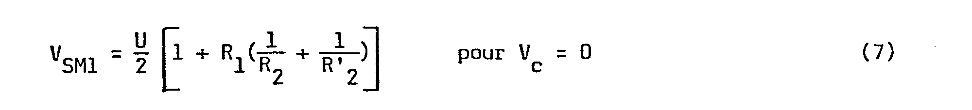
- the signal V SM leaving the modulator just before time t l can take two values as a function of the test control signal V: c
- the current i passing through the network 33 then reverses, keeping one of the two values i 1 or i 2 , depending on the value of the data signal V D.
- the output signal V S decreases linearly with a slope having the same absolute value as the slope after the instant t o .
- the operation is identical to that which has been explained for time t o .
- the network 46 It is advantageous for the network 46 to include a potentiometer 50 connected as shown in FIG. 2. In this way the fine adjustment of the multiplication factor n can be carried out by the slider of this potentiometer without practically modifying the frequencies f 1 and f 2 , because the sum R ' 2 + R 2 remains fixed.
- modulator of FIG. 2 requires only one power source, since the reference voltages applied to the inputs of operational amplifiers can be obtained by a voltage divider bridge connected to this power source. Finally, it is advantageous for the active circuits to be produced in CMOS technology, which reduces the output resistance of these circuits and therefore their absolute variation with temperature.
- This embodiment has the particular advantage that all of the circuits are implemented in both operating modes.
- the filter shown in FIG. 4 is an active filter comprising an operational amplifier 60 which is supplied by the voltage source U.
- the filter comprises an input terminal 61 which receives the input voltage v e and an output terminal 62 which is connected to the output of amplifier 60 and which supplies the output voltage v.
- Terminal input 61 is connected to one end of a voltage divider formed by the resistors in series 63, 64 having the values R 16 and R 15 respectively .
- the other end of this voltage divider is grounded and its intermediate terminal is connected to the non-inverting input of amplifier 60.
- the inverting input of this amplifier is connected to the common terminal of the two resistors 65 and 66 having the values R 12 and R 13 respectively .
- resistor 65 is connected to the output of amplifier 60 and the other terminal of resistor 66 is grounded.
- the series connection of the two capacitors 67 and 68 having the same value C 1 .
- the common terminal of these two capacitors is connected to terminal 61 of the filter through a circuit 69 behaving like a resistor with variable ohmic value R 11 with the test control signal V C.
- This circuit 69 is formed by a resistor 70 at the terminals of which is connected the series connection of the resistor 71 and the emitter-collector space of the npn transistor 72. Between the base and the emitter of this transistor is connected, in the direction indicated, the diode 73.
- the base of the transistor 72 receives the test control signal V C through the resistor 74. In normal operation the transistor 72 is blocked and the ohmic value R 11 of the circuit 69 is that of the resistor 70. During a test, the transistor 72 is on and the ohmic value R 11 of the circuit 69 is that of the parallel connection of the resistors 70 and 71.
- the curve LP of FIG. 5 represents, as a function of the frequency f, the gain
- the second term of formula (14) is the transfer function of a bandpass filter whose bandwidth is approximate t i tively centered on the frequency
- the elements of the filter are determined so that its transfer function is that of a low-pass filter, the gain of which has the shape of the curve LP shown in FIG. 5, that is, it has only the first term of the formula (14) and does not have the second term.
- the filter elements can be determined from the 5 equations (15).
- a ' 0 to eliminate the second term of the formula (14).
- circuit 69 determines the ohmic value of circuit 69, determined as just indicated so that the filter operates in low pass.
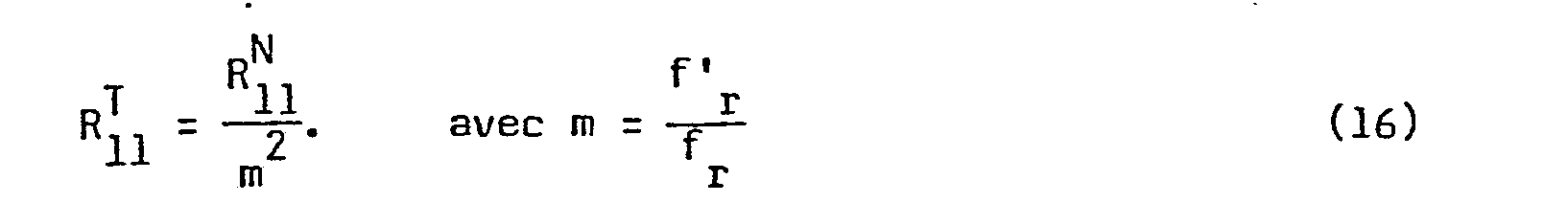
- the filter For the filter to work, during a test, in bandpass to transmit the two frequencies f ' 1 , f' 2 centered around the resonant frequency f ' r of the bandpass filter, it suffices to give to the circuit 69 another ohmic value , such as :
- the transition from the gain curve LP of a low-pass filter for normal operation to the gain curve BP of a band-pass filter for test operation is carried out simply by changing the ohmic value of the circuit 69 , from at , according to formula (16).
- the change in the ohmic value of circuit 69 is carried out by means of the test control signal V c , as explained.
Abstract
Ce système de test est utilisé pour tester un modem (1) dont le modulateur (11) est constitué par un multivibrateur qui fournit en fonctionnement normal deux fréquences f1, f2 sous l'action du signal de données VD et qui est connecté à un filtre d'émission (12). Sous l'action du signal de commande de test Vc, le multivibrateur est modifié pour fournir deux fréquences de test f'1 = nf1, f'2 = nf2, n étant sensiblement égal au rapport f0,<F0> F0 étant la valeur moyenne des fréquences reçues par le modem en fonctionnement normal, f0 étant la valeur moyenne des fréquences f1, f2; en même temps le filtre d'émission est modifié pour transmettre les deux fréquences f'1, f'2 sous l'action du signal de commande de test. Application : transmission de données.This test system is used to test a modem (1) whose modulator (11) consists of a multivibrator which provides in normal operation two frequencies f1, f2 under the action of the data signal VD and which is connected to a filter transmission (12). Under the action of the test control signal Vc, the multivibrator is modified to provide two test frequencies f'1 = nf1, f'2 = nf2, n being substantially equal to the ratio f0, <F0> F0 being the mean value frequencies received by the modem during normal operation, f0 being the average value of the frequencies f1, f2; at the same time the emission filter is modified to transmit the two frequencies f'1, f'2 under the action of the test control signal. Application: data transmission.
Description
L'invention concerne un système de test local d'un modem utilisant la modulation par déplacement de fréquence et couplé à une ligne de transmission deux fils, les deux fréquences émises par le modem étant inférieures aux deux fréquences reçues et étant formées par un modulateur constitué par un multivibrateur commandé par les données et connecté à un filtre d'émission, le système de test comportant des moyens pour boucler le modem du côté de la ligne de transmission sous l'action d'un signal de commande de test.The invention relates to a local test system for a modem using frequency shift modulation and coupled to a two-wire transmission line, the two frequencies transmitted by the modem being less than the two frequencies received and being formed by a modulator constituted by a data-controlled multivibrator connected to a transmission filter, the test system comprising means for looping the modem on the side of the transmission line under the action of a test command signal.
Un modem du genre envisagé ci-dessus est par exemple un modem défini dans l'avis V 23 du CCITT, transmettant des données à 75 bauds sous forme de deux fréquences f ± Δf avec f = 420 Hz et Δf = 30 Hz, et recevant des données à 1200 bauds sous forme de deux fréquences F0 ± ΔF avec F = 1700 Hz et ΔF = 400 Hz. Ces modems peuvent trouver une très large utilisation dans des applications telles que l'annuaire électronique, le vidéo texte, etc... et il est important qu'ils soient simples et peu coûteux à construire. Une solution pour réaliser le modulateur est d'utiliser un circuit multivibrateur à fréquence commandée par les données, comme le décrit par exemple le brevet américain n° 4 039 952.A modem of the kind envisaged above is for example a modem defined in CCITT
Par ailleurs, dans ces modems on doit prévoir un système local de test, ce test étant effectué, après avoir réalisé du côté de la ligne de transmission un bouclage du modem, appelé bouclage 3 dans l'avis V 54 du CCITT. Selon cet avis, la boucle réalisée pour le test doit inclure le nombre maximum de circuits utilisés en fonctionnement normal.Furthermore, in these modems, a local test system must be provided, this test being carried out, after having performed a loopback of the modem on the side of the transmission line, called loopback 3 in CCITT opinion V 54. According to this opinion, the loop made for the test must include the maximum number of circuits used in normal operation.
La présente invention vise à fournir un système de test simple et efficace pour vérifier, avec un minimum de changement dans le modem, le bon fonctionnement de tous les circuits utilisés dans le fonctionnement normal lorsque le modem est bouclé du côté de la ligne de transmission.The present invention aims to provide a simple and effective test system for verifying, with a minimum of change in the modem, the proper functioning of all the circuits used in normal operation when the modem is looped from the side of the transmission line.
Conformément à l'invention le multivibrateur commandé par les données est agencé pour fournir, sous l'action du signal de commande de test, deux fréquences de test résultant de la multiplication desdites fréquences émises par un facteur sensiblement égal au rapport des valeurs moyennes desdites fréquences reçues et émises, et le filtre d'émission est agencé pour transmettre lesdites fréquences de test sous l'action du signal de commande de test.In accordance with the invention, the data-controlled multivibrator is arranged to supply, under the action of the test control signal, two test frequencies resulting from the multiplication of said frequencies emitted by a factor substantially equal to the ratio of the average values of said frequencies received and transmitted, and the transmission filter is arranged to transmit said test frequencies under the action of the test control signal.
Dans un mode de réalisation préféré du multivibrateur constituant le modulateur et décrit en détail par la suite, la multiplication des fréquences peut être effectuée après une commutation très simple de deux résistances, sans aucun changement dans le circuit déplaçant la fréquence en fonction des données. Généralement le filtre d'émission est un filtre passe-bas en fonctionnement normal. Dans un mode de réalisation préféré, décrit par la suite, le filtre d'émission est transformé en filtre passe-bande pour transmettre les deux fréquences de test et cette transformation est effectuée par un simple changement de la valeur d'une résistance. Aucun autre changement n'est nécessaire dans la voie réception pour tester le modem, puisque les fréquences appliquées à la voie réception lors d'un test ont la même valeur moyenne que celle des fréquences reçues en fonctionnement normal.In a preferred embodiment of the multivibrator constituting the modulator and described in detail below, the multiplication of the frequencies can be carried out after a very simple switching of two resistors, without any change in the circuit displacing the frequency as a function of the data. Generally the emission filter is a low pass filter in normal operation. In a preferred embodiment, described below, the emission filter is transformed into a bandpass filter to transmit the two test frequencies and this transformation is carried out by a simple change in the value of a resistor. No other change is necessary in the reception channel to test the modem, since the frequencies applied to the reception channel during a test have the same average value as that of the frequencies received in normal operation.
La description suivante, en regard des dessins annexés, le tout donné à titre d'exemple, fera bien comprendre comment l'invention peut être réalisée.
- La figure 1 est le schéma de principe d'un modem auquel est associé le système de test de l'invention.
- La figure 2 est le schéma d'un mode de réalisation d'un modulateur convenant pour le système de test de l'invention.
- La figure 3 représente des diagrammes de signaux destinés à expliquer le fonctionnement du modulateur de.la figure 2.
- La figure 4 est le schéma d'un mode de réalisation d'un filtre d'émission convenant pour le système de test de l'invention.
- La figure 5 représente le gain du filtre d'émission de la figure 4,en fonctionnement normal et en fonctionnement de test.
- La figure 1 montre le schéma de principe d'un modem relié à un terminal et des liaisons à effectuer pour procéder au test loc- cal de ce modem. On suppose par la suite, à titre d'exemple, qu'il s'agit d'un modem 75 bauds/1200 bauds, défini plus haut, connecté à un terminal installé chez un abonné téléphonique.
- FIG. 1 is the block diagram of a modem with which the test system of the invention is associated.
- FIG. 2 is the diagram of an embodiment of a modulator suitable for the test system of the invention.
- FIG. 3 represents diagrams of signals intended to explain the operation of the modulator of FIG. 2.
- FIG. 4 is the diagram of an embodiment of an emission filter suitable for the test system of the invention.
- FIG. 5 represents the gain of the emission filter of FIG. 4, in normal operation and in test operation.
- Figure 1 shows the block diagram of a modem connected to a terminal and the connections to be made to carry out the local test of this modem. It is subsequently assumed, by way of example, that it is a 75 baud / 1200 baud modem, defined above, connected to a terminal installed at a telephone subscriber.
Le modem 1 est relié par ses bornes 2 et 3 aux deux fils LI L2 d'une ligne de transmission téléphonique. Il reçoit sur sa borne 4 des données VD provenant de la partie d'émission 5 d'un terminal et fournit des données par sa borne 6 à la partie réception 7 du terminal. Le modem est en outre relié par ses bornes 8 et 9 à un poste téléphonique 30 et enfin par sa borne 10, il peut recevoir un signal de commande de test VC provenant de la partie émission 5 du terminal.The modem 1 is connected by its terminals 2 and 3 to the two wires L I L 2 of a telephone transmission line. It receives on its
On décrit d'abord le modem dans son fonctionnement normal. Ce modem utilise la modulation par déplacement de fréquence et sa voie d'émission comporte un modulateur 11 qui, dans l'exemple choisi, reçoit les données provenant de la borne 4 à la vitesse de 75 bits/S et fournit un signal prenant en fonction des données les fréquence f1 = 420 + 30 Hz et f2 = 420 - 30 Hz. Ce modulateur est un oscillateur du type multivibrateur et dans un mode préféré de réalisation décrit par la suite, il fournit un signal à forme triangulaire qui est filtré par le filtre d'émission 12. Ce filtre 12 est en fonctionnement normal un filtre passe-bas qui doit transmettre les deux fréquences f1, f et atténuer les fréquences supérieures pour respecter diverses exigences spécifiées. Ce filtre 12 est un filtre actif dont on donnera par la suite un mode de réalisation et qui est représenté sur la figure 1 de façon simplifiée par un réseau de filtrage 13 à résistances et capacités et par un amplificateur 14. La sortie du filtre 12 est reliée à l'accès émission 15 du circuit de couplage 16 destiné à coupler le modem à la ligne de transmission L1 L2.We first describe the modem in its normal operation. This modem uses frequency shift modulation and its transmission channel includes a modulator 11 which, in the example chosen, receives data from
A l'accès réception 17 de ce circuit de couplage est connectée la voie réception du modem qui traite un signal modulé par déplacement de fréquence provenant de la ligne de transmission L1 L2 ; dans l'exemple choisi la rapidité de modulation est de 1200 bauds et les deux fréquences reçues sont, en fonction des données, F1 = 1700 + 400 Hz et F2 = 1700 - 400 Hz. La voie réception comporte en cascade, un filtre réception 18 qui transmet les fréquences F1, F2 avec une bande passante centrée sur la valeur moyenne F = 1700 Hz des fréquences F1, F2 et un démodulateur 19 qui fournit les données restituées à la borne 6.To the
Dans le mode de réalisation représenté le circuit de couplage 16 comporte un amplificateur opérationnel 20 qui est alimenté par la tension U fournie par la borne positive d'une source d'alimentation dont l'autre borne est à la masse. Les deux entrées de cet amplificateur 20 sont reliées à l'accès émission 15 par les deux résistances 21 et 22 et sa sortie est reliée à l'accès réception 17. L'entrée inverseuse de l'amplificateur 20 est reliée à sa sortie à travers la résistance 23 et l'entrée non inverseuse est reliée à une borne portée à la tension ![]()
![]()
Pour effectuer le test du modem, on doit réaliser son bouclage du côté de la ligne de transmission de façon qu'aucun signal ne soit fourni pendant le test sur la ligne de transmission et qu'un signal de données provenant de la chaîne émission 11, 12, puisse être reconnu dans la chaîne de réception 18, 19. Pour effectuer le bouclage du modem il est classique de déséquilibrer le circuit de couplage 16 et ce déséquilibre est réalisé en court-circuitant l'enroulement 26 du transformateur 25. Pour réaliser le bouclage du modem au noment d'un test, on a prévu sur la figure 1 un relais constitué d'une bobine 27 et d'un contact inverseur 28. La bobine 27 a une borne à la tension U et l'autre borne reçoit le signal de commande de test Vc qui vaut 0 en fonctionnement normal et U pendant un test. Ce signal V c est élaboré, par exemple comme l'indique la figure, au moyen du circuit commutateur manuel 29 qui en fonctionnement normal est sur la position N et pendant un test est sur la position T. On voit sur la figure qu'en fonctionnement normal du modem, le relais est au travail, le contact inverseur 28 est sur la position t et les deux bornes de l'enroulement 26 du transformateur 25 sont reliées aux deux fils L1, L2 de la ligne de transmission. Pendant le test du modem, le relais est au repos, le contact inverseur 28 est sur la position r et l'enroulement 26 est court-circuité. On voit en outre que le poste téléphonique 30 relié aux bornes 8, 9 est court-circuité pendant le fonctionnement normal du modem et relié à la ligne de transmission le reste du temps.To perform the modem test, it must be looped through the transmission line so that no signal is supplied during the test on the transmission line and that a data signal from the transmission chain 11, 12, can be recognized in the
Le bouclage du modem étant réalisé comme on vient de l'indiquer, la présente invention fournit les moyens d'adapter pendant le test, avec un minimum de modifications, la chaîne d'émission fonctionnant normalement à 420 ± 30 Hz à la chaîne de réception fonctionnant normalement à 1700 ± 400 Hz, de façon à pouvoir vérifier le bon fonctionnement de tous les circuits du modem.The loopback of the modem being carried out as just indicated, the present invention provides the means to adapt during the test, with a minimum of modifications, the transmission chain operating normally at 420 ± 30 Hz to the reception chain. operating normally at 1700 ± 400 Hz, so that you can check that all the modem circuits are working properly.
Conformément à l'invention, le multivibrateur constituant le modulateur 11 est commandé par le signal de commande de test V pour fournir en fonction des données, pendant un test, deux fréquences f'1 et f'2 résultant de la multiplication des fréquences fI et f2 émises en fonctionnement normal, par un facteur n sensiblement égal au rapport ![]()
![]()
Dans l'exemple choisi, les fréquences f'1 et f'2 à four- nir par le modulateur 11 pendant un test sont ![]()
![]()
La figure 2 représente un mode de réalisation préféré du modulateur 11, réalisé sous forme d'un multivibrateur aisément commutable pour fournir en fonction des données, soit les fréquences f1, f2 utilisées en fonctionnement normal, soit les fréquences f'1 = nf1 et f'2 = nf2.FIG. 2 represents a preferred embodiment of the modulator 11, produced in the form of an easily switchable multivibrator for supplying, as a function of the data, either the frequencies f 1 , f 2 used in normal operation, or the frequencies f ' 1 = nf 1 and f ' 2 = nf 2 .
Le modulateur de la figure 2 comporte un circuit intégrateur formé par un amplificateur opérationnel 31, par un condensateur 32 de capacité C connecté entre l'entrée inverseuse et la sortie de l'amplificateur 31, et enfin par un réseau 33 dont une borne 34 est reliée à l'entrée inverseuse de l'amplificateur opérationnel 31. Ce réseau 33 reçoit sur sa borne 35 une tension bivalente Vi et sur sa borne de commande 36, le signal de données VD. Comme on l'expliquera par la suite, il circule entre les bornes 34 et 35 du réseau 33 un courant dépendant notamment de la valeur du signal de données VD. Le réseau 33 est formé à cet effet par les deux résistances en série 37 et 38 ayant respectivement les valeurs Ro et R3 et connectées entre les bornes 34 et 35 et par la résistance 39 ayant la valeur R4 et connectée entre la borne commune aux résistances 37 et 38 et la sortie du circuit "OU exclusif" 40. Une entrée de ce circuit "OU exclusif" est reliée à la borne 35 du réseau 33 et l'autre entrée est reliée à la borne de commande 36 de ce réseau. L'amplificateur 31 et le circuit "OU exclusif" 40 sont alimentés par la source de tension U. L'entrée non inverseuse de l'amplificateur 31 est portée à la tension 2. Le signal de sortie de l'amplificateur 31 constitue le signal de sortie VS du modulateur.The modulator of FIG. 2 comprises an integrator circuit formed by an operational amplifier 31, by a
La sortie de l'amplificateur opérationnel 31 est reliée par l'intermédiaire d'une résistance 41 de valeur R1 à l'entrée inverseuse d'un amplificateur opérationnel 42 formant un circuit comparateur. Ce circuit comparateur 42 est également alimenté par la source de tension U et son entrée non inverseuse est portée à la tension ![]()
![]()
Le réseau 46 est constitué à cet effet par la résistance 49 connectée entre la borne 44 et une extrémité du potentiomètre 50 et par la résistance 51 connectée entre l'autre extrémité de ce potentiomètre et la sortie du circuit "OU exclusif" 52. Le curseur du potentiomètre 50 est relié à l'entrée inverseuse du circuit comparateur 42. La valeur des résistances insérées entre le curseur et la borne 44 est appelée par la suite R2 et la valeur des résistances insérées entre ce curseur et la sortie du circuit "OU exclusif" 52 est appelée R'2. Enfin les deux entrées de ce circuit "OU exclusif" sont reliées respectivement aux bornes 44 et 47 du réseau 46.The
A la sortie du circuit inverseur 43 on obtient une tension bivalente Vi qui passe de la valeur 0 à la valeur U quand la tension V1 sur l'entrée inverseuse du circuit comparateur 42 devient juste plus grande que la tension ![]()
![]()
![]()
![]()
![]()
![]()
![]()
![]()
![]()
![]()
![]()
![]()
On va examiner maintenant le fonctionnement du modulateur de la figure 2. Ce fonctionnement est illustré par les diagrammes de la figure 3. Le diagramme 3a représente le signal V1 à l'entrée inverseuse du circuit comparateur 42 ; le diagramme 3b représente le signal bivalent Vi à la sortie du circuit inverseur 43 et le diagramme 3c représente le signal de sortie VS du modulateur.We will now examine the operation of the modulator in Figure 2. This operation is illustrated by the diagrams in Figure 3. Diagram 3a represents the signal V 1 at the input invert threshold of
On se place initialement juste avant l'instant to où le signal V1 décroissant atteint juste la tension ![]()


![]()
A l'instant t , le comparateur 42 bascule, le signal Vi tombe à zéro et le signal V1 descend brusquement à une valeur inférieure à ![]()
![]()


![]()
![]()
Le signal V1 croft également linéairement et on peut montrer que juste avant l'instant t1 où il atteint la tension ![]()

![]()
A l'instant t1, le comparateur 42 bascule, le circuit inverseur 43 fournit le signal Vi = U et le signal V1 monte brusquement à une valeur supérieure à ![]()
![]()
On voit aisément d'après le diagramme 3c que la pente de croissance ou de décroissance du signal de sortie VS peut s'écrire aussi 


Ces formules montrent que le facteur de multiplication n tel que f'1 = nf1 et f'2 = nf2, a la valeur :
Il résulte clairement du schéma de la figure 2 que tous les composants du modulateur qui sont utilisés en fonctionnement normal, sont également mis en oeuvre lors d'un test. On peut remarquer en outre que la modulation de fréquence par le signal de données VD est effectuée exactement de la même manière dans les deux modes de fonctionnement, ce qui contribue encore à l'efficacité du test.It is clear from the diagram in FIG. 2 that all the components of the modulator which are used in normal operation are also used during a test. It can also be noted that the frequency modulation by the data signal V D is carried out in exactly the same way in the two operating modes, which further contributes to the efficiency of the test.
Un avantage supplémentaire du modulateur de la figure 2 est de ne nécessiter qu'une seule source d'alimentation, puisque les tensions de référence ![]()
![]()
La figure 4 montre le schéma d'un mode de réalisation d'un filtre d'émission 12 aisément commutable d'une fonction de filtre passe-bas pour transmettre les fréquences f1, f2 en fonctionnement normal à une fonction de filtre passe-bande pour transmettre lors d'un test les fréquences f'1 = nf1 et f'2 = nf2. Ce mode de réalisation présente notamment l'avantage que tous les circuits sont mis en oeuvre dans les deux modes de fonctionnement.FIG. 4 shows the diagram of an embodiment of an easily switchable emission filter 12 of a low-pass filter function for transmitting the frequencies f 1 , f 2 in normal operation to a pass-filter function band to transmit during a test the frequencies f ' 1 = nf 1 and f' 2 = nf 2 . This embodiment has the particular advantage that all of the circuits are implemented in both operating modes.
Le filtre montré sur la figure 4 est un filtre actif comportant un amplificateur opérationnel 60 qui est alimenté par la source de tension U. Le filtre comporte une borne d'entrée 61 qui reçoit la tension d'entrée ve et une borne de sortie 62 qui est reliée à la sortie de l'amplificateur 60 et qui fournit la tension de sortie v . La borne d'entrée 61 est reliée à une extrémité d'un diviseur de tension formé par les résistances en série 63, 64 ayant respectivement les valeurs R16 et R15. L'autre extrémité de ce diviseur de tension est à la masse et sa borne intermédiaire est reliée à l'entrée non inverseuse de l'amplificateur 60. L'entrée inverseuse de cet amplificateur est connectée à la borne commune des deux résistances 65 et 66 ayant respectivement les valeurs R12 et R13. L'autre borne de la résistance 65 est reliée à la sortie de l'amplificateur 60 et l'autre borne de la résistance 66 est à la masse. Aux bornes de la résistance 65 est connecté le montage en série des deux condensateurs 67 et 68 ayant la même valeur C1. La borne commune de ces deux condensateurs est reliée à la borne 61 du filtre à travers un circuit 69 se comportant comme une résistance à valeur ohmique R11 variable avec le signal de commande de test VC. Ce circuit 69 est formé par une résistance 70 aux bornes de laquelle est connecté le montage en série de la résistance 71 et de l'espace émetteur-collecteur du transistor npn 72. Entre la base et l'émetteur de ce transistor est connectée, dans le sens indiqué, la diode 73. La base du transistor 72 reçoit le signal de commande de test VC à travers la résistance 74. En fonctionnement normal le transistor 72 est bloqué et la valeur ohmique R11 du circuit 69 est celle de la résistance 70. Pendant un test le transistor 72 est passant et la valeur ohmique R11 du circuit 69 est celle du montage en parallèle des résistances 70 et 71.The filter shown in FIG. 4 is an active filter comprising an
On peut montrer que la fonction de transfert 1


Le spécialiste peut voir aisément que pour K < 1 le premier terme de la formule (14) est la fonction de transfert d'un passe-bas du deuxième ordre ayant une transmission maximale pour la fréquence de résonance ![]()
![]()
![]()
![]()
Le deuxième terme de la formule (14) est la fonction de transfert d'un filtre passe-bande, dont la bande passante est approxima- tivement centrée sur la fréquence ![]()
![]()
Pour définir les deux configurations à donner au filtre pour le fonctionnement normal et le fonctionnement en test, on utilise par la suite l'exemple déjà cité où les deux fréquences f1, f2 à transmettre en fonctionnement normal ont les valeurs 420 + 30 Hz et les deux fréquences f'1, f'2 à transmettre en fonctionnement de test ont les valeurs 1700 ± 121 Hz.To define the two configurations to be given to the filter for normal operation and test operation, we use below the example already cited where the two frequencies f 1 , f 2 to be transmitted in normal operation have the values 420 + 30 Hz and the two frequencies f ' 1 , f' 2 to be transmitted in test operation have the values 1700 ± 121 Hz.
Pour le fonctionnement normal, on détermine les éléments du filtre pour que sa fonction de transfert soit celle d'un filtre passe-bas dont le gain a la forme de la courbe LP montrée à la figure 5, c'est-à-dire ne comporte que le premier terme de la formule (14) et ne comporte pas le deuxième terme. La détermination des éléments du filtre peut être faite à partir des 5 équations (15). On se fixe notamment A' = 0 pour éliminer le deuxième terme de la formule (14). On se fixe la fré- quence ![]()
![]()
On appelle ![]()
![]()
![]()
![]()
En effet, en donnant au circuit 69 une valeur ohmique différente de ![]()
![]()
- - ω devient ω' = 2πf' = mw r r r r
- - Q devient Q' = mQ
- - A' devient

- - A et K sont inchangés. La fonction de transfert du filtre devient :


vers 0. Le gain du filtre correspondant à la formule (17) a, en fonction de la fréquence, l'allure représentée par la courbe BP sur la figure 5, ce gain étant exprimé en dB. On a un gain maximum pour la fréquence f'r. Les deux fréquences f'1 et f'2 sont situées de part et d'autre de la fréquence f'r et sont transmises avec un affaiblissement réduit. Les valeurs numériques indiquées sur les axes de la figure 5 correspondent à un filtre d'émission réalisé pour le modem choisi ci-dessus comme exemple.
- - ω becomes ω '= 2πf' = mw rrrr
- - Q becomes Q '= mQ
- - A 'becomes
- - A and K are unchanged. The filter transfer function becomes:
Le passage de la courbe de gain LP d'un filtre passe-bas pour le fonctionnement normal à la courbe de gain BP d'un filtre passe-bande pour le fonctionnement en test est effectué simplement en chan- geant la valeur ohmique du circuit 69, de ![]()
![]()
![]()
![]()
![]()
![]()
Claims (7)
Applications Claiming Priority (2)
| Application Number | Priority Date | Filing Date | Title |
|---|---|---|---|
| FR8013867 | 1980-06-23 | ||
| FR8013867A FR2485306A1 (en) | 1980-06-23 | 1980-06-23 | LOCAL TESTING SYSTEM OF A MODEM USING FREQUENCY DISPLACEMENT MODULATION |
Publications (2)
| Publication Number | Publication Date |
|---|---|
| EP0042642A1 true EP0042642A1 (en) | 1981-12-30 |
| EP0042642B1 EP0042642B1 (en) | 1984-05-09 |
Family
ID=9243386
Family Applications (1)
| Application Number | Title | Priority Date | Filing Date |
|---|---|---|---|
| EP81200637A Expired EP0042642B1 (en) | 1980-06-23 | 1981-06-11 | Fsk modem local test system |
Country Status (5)
| Country | Link |
|---|---|
| US (1) | US4393508A (en) |
| EP (1) | EP0042642B1 (en) |
| JP (1) | JPS5729962A (en) |
| DE (1) | DE3163481D1 (en) |
| FR (1) | FR2485306A1 (en) |
Families Citing this family (28)
| Publication number | Priority date | Publication date | Assignee | Title |
|---|---|---|---|---|
| US4600779A (en) * | 1982-03-29 | 1986-07-15 | Bristol-Myers Company | Substituted 3,4-diamino-1,2,5-thiadiazoles having histamine H2 -receptor antagonist activity |
| US4756007A (en) * | 1984-03-08 | 1988-07-05 | Codex Corporation | Adaptive communication rate modem |
| GB8913952D0 (en) * | 1989-06-16 | 1989-08-02 | Texas Instruments Ltd | Line interface circuit and method of testing such a circuit |
| US6243446B1 (en) * | 1997-03-11 | 2001-06-05 | Inline Connections Corporation | Distributed splitter for data transmission over twisted wire pairs |
| US5010399A (en) * | 1989-07-14 | 1991-04-23 | Inline Connection Corporation | Video transmission and control system utilizing internal telephone lines |
| US6480510B1 (en) | 1998-07-28 | 2002-11-12 | Serconet Ltd. | Local area network of serial intelligent cells |
| US6532279B1 (en) * | 1999-06-11 | 2003-03-11 | David D. Goodman | High-speed data communication over a residential telephone wiring network |
| US6690677B1 (en) | 1999-07-20 | 2004-02-10 | Serconet Ltd. | Network for telephony and data communication |
| US6564349B1 (en) * | 2000-02-25 | 2003-05-13 | Ericsson Inc. | Built-in self-test systems and methods for integrated circuit baseband quadrature modulators |
| US6549616B1 (en) | 2000-03-20 | 2003-04-15 | Serconet Ltd. | Telephone outlet for implementing a local area network over telephone lines and a local area network using such outlets |
| IL135744A (en) | 2000-04-18 | 2008-08-07 | Mosaid Technologies Inc | Telephone communication system over a single telephone line |
| US6842459B1 (en) | 2000-04-19 | 2005-01-11 | Serconet Ltd. | Network combining wired and non-wired segments |
| IL144158A (en) | 2001-07-05 | 2011-06-30 | Mosaid Technologies Inc | Outlet for connecting an analog telephone set to a digital data network carrying voice signals in digital form |
| WO2003039150A1 (en) | 2001-10-11 | 2003-05-08 | Serconet Ltd. | Outlet with analog signal adapter, a method for use thereof and a network using said outlet |
| IL154234A (en) | 2003-01-30 | 2010-12-30 | Mosaid Technologies Inc | Method and system for providing dc power on local telephone lines |
| IL154921A (en) | 2003-03-13 | 2011-02-28 | Mosaid Technologies Inc | Telephone system having multiple distinct sources and accessories therefor |
| IL157787A (en) | 2003-09-07 | 2010-12-30 | Mosaid Technologies Inc | Modular outlet for data communications network |
| IL159838A0 (en) | 2004-01-13 | 2004-06-20 | Yehuda Binder | Information device |
| IL161869A (en) | 2004-05-06 | 2014-05-28 | Serconet Ltd | System and method for carrying a wireless based signal over wiring |
| US7873058B2 (en) | 2004-11-08 | 2011-01-18 | Mosaid Technologies Incorporated | Outlet with analog signal adapter, a method for use thereof and a network using said outlet |
| US7813451B2 (en) | 2006-01-11 | 2010-10-12 | Mobileaccess Networks Ltd. | Apparatus and method for frequency shifting of a wireless signal and systems using frequency shifting |
| US8594133B2 (en) * | 2007-10-22 | 2013-11-26 | Corning Mobileaccess Ltd. | Communication system using low bandwidth wires |
| US8175649B2 (en) | 2008-06-20 | 2012-05-08 | Corning Mobileaccess Ltd | Method and system for real time control of an active antenna over a distributed antenna system |
| EP2100492A1 (en) | 2008-03-10 | 2009-09-16 | Wiedenmann GmbH | Soil cultivation device |
| DE102008017242B4 (en) | 2008-03-10 | 2011-12-22 | Wiedenmann Gmbh | Harrow |
| US8897215B2 (en) * | 2009-02-08 | 2014-11-25 | Corning Optical Communications Wireless Ltd | Communication system using cables carrying ethernet signals |
| EP2829152A2 (en) | 2012-03-23 | 2015-01-28 | Corning Optical Communications Wireless Ltd. | Radio-frequency integrated circuit (rfic) chip(s) for providing distributed antenna system functionalities, and related components, systems, and methods |
| US9184960B1 (en) | 2014-09-25 | 2015-11-10 | Corning Optical Communications Wireless Ltd | Frequency shifting a communications signal(s) in a multi-frequency distributed antenna system (DAS) to avoid or reduce frequency interference |
Citations (3)
| Publication number | Priority date | Publication date | Assignee | Title |
|---|---|---|---|---|
| US4015220A (en) * | 1975-11-03 | 1977-03-29 | R F L Industries, Inc. | Frequency shift keyed toned generator |
| FR2386202A1 (en) * | 1977-03-31 | 1978-10-27 | Cit Alcatel | MODEMS local test system in duplex telephone line - converts transmitters frequencies using modulator and local oscillator |
| EP0017301A1 (en) * | 1979-04-06 | 1980-10-15 | Telecommunications Radioelectriques Et Telephoniques T.R.T. | Frequency shift modulator |
Family Cites Families (3)
| Publication number | Priority date | Publication date | Assignee | Title |
|---|---|---|---|---|
| US3793486A (en) * | 1968-12-11 | 1974-02-19 | L Koziol | Data set system employing active filters and multivibrator timing |
| US3655915A (en) * | 1970-05-07 | 1972-04-11 | Gen Datacomm Ind Inc | Closed loop test method and apparatus for duplex data transmission modem |
| US3719779A (en) * | 1970-05-22 | 1973-03-06 | American Chain & Cable Co | High speed frequency shift keyed transmission system |
-
1980
- 1980-06-23 FR FR8013867A patent/FR2485306A1/en active Pending
-
1981
- 1981-06-11 DE DE8181200637T patent/DE3163481D1/en not_active Expired
- 1981-06-11 EP EP81200637A patent/EP0042642B1/en not_active Expired
- 1981-06-22 JP JP9645981A patent/JPS5729962A/en active Granted
- 1981-06-23 US US06/276,580 patent/US4393508A/en not_active Expired - Fee Related
Patent Citations (3)
| Publication number | Priority date | Publication date | Assignee | Title |
|---|---|---|---|---|
| US4015220A (en) * | 1975-11-03 | 1977-03-29 | R F L Industries, Inc. | Frequency shift keyed toned generator |
| FR2386202A1 (en) * | 1977-03-31 | 1978-10-27 | Cit Alcatel | MODEMS local test system in duplex telephone line - converts transmitters frequencies using modulator and local oscillator |
| EP0017301A1 (en) * | 1979-04-06 | 1980-10-15 | Telecommunications Radioelectriques Et Telephoniques T.R.T. | Frequency shift modulator |
Non-Patent Citations (1)
| Title |
|---|
| ELECTRONICS AND COMMUNICATIONS IN JAPAN, vol. 57-A, no. 2, 1974 WASHINGTON (US) S. SHIMADA et al.: "Fs modulator suitable for hybrid IC", pages 29-38. * |
Also Published As
| Publication number | Publication date |
|---|---|
| JPS5729962A (en) | 1982-02-18 |
| JPH0128910B2 (en) | 1989-06-06 |
| EP0042642B1 (en) | 1984-05-09 |
| US4393508A (en) | 1983-07-12 |
| DE3163481D1 (en) | 1984-06-14 |
| FR2485306A1 (en) | 1981-12-24 |
Similar Documents
| Publication | Publication Date | Title |
|---|---|---|
| EP0042642B1 (en) | Fsk modem local test system | |
| EP0016705B1 (en) | R.f. stage with automatic gain control and receiver comprising such a circuit | |
| BE898477A (en) | Digital signal transmission system. | |
| FR2502871A1 (en) | SIGNAL COMBINATION AND SWITCHING SYSTEM FOR A RADIO COMMUNICATION SYSTEM | |
| CH624517A5 (en) | Electronic hybrid circuit | |
| EP0014505B1 (en) | Device testing system provided with an echo suppressor | |
| EP0756389A1 (en) | Assignment circuit for a transmission channel on the mains network | |
| CH629632A5 (en) | DEVICE FOR AUTOMATICALLY CONTROLLING THE GAIN OF A RECEPTION CHANNEL OF A TRANSMISSION INSTALLATION COMPRISING OPTICAL LINKS. | |
| EP0199332B1 (en) | Wide-band receiver for optical signals | |
| EP0017301B1 (en) | Frequency shift modulator | |
| EP0021509A1 (en) | Electronic subscriber connector | |
| EP0042641A1 (en) | Frequency demodulator using a delay circuit, the delay of which varies according to the received frequency | |
| EP0755128A1 (en) | Transmission circuit for binary data on the mains network using several transmission channels | |
| FR2859856A1 (en) | Remote supply system for e.g. information processing equipment such as telephone, has converter to deliver electrical power signal presenting voltage and intensity in determined operating ranges to equipment | |
| EP0098003B1 (en) | Transmitter circuit for modems using frequency shift modulation | |
| EP0415316B1 (en) | Carrier recovery device for a Costas loop | |
| FR2458960A1 (en) | SYSTEM FOR TRANSMITTING BINARY SIGNALS BETWEEN THE COMPONENTS OF AN ALARM INSTALLATION | |
| EP0362583A1 (en) | Microwave modulator for two phase states : O, Pi, with very small losses | |
| EP0098668B1 (en) | Modulator for analog data transmission | |
| EP1493228B1 (en) | Application-specific integrated circuit for a low-pass filtering device used for decoupling xdsl channels | |
| EP0889619A1 (en) | FSK modulator with a phase locked loop | |
| EP0404630B1 (en) | Device for receiving information supported by two capacitor-coupled lines, especially for vehicles | |
| EP0404001B1 (en) | Signalisation detector, for metering type signals, for a telephone trunk | |
| CA2032245A1 (en) | Phase-locked loop demodulator | |
| FR2478908A1 (en) |
Legal Events
| Date | Code | Title | Description |
|---|---|---|---|
| PUAI | Public reference made under article 153(3) epc to a published international application that has entered the european phase |
Free format text: ORIGINAL CODE: 0009012 |
|
| AK | Designated contracting states |
Designated state(s): DE FR GB IT NL SE |
|
| 17P | Request for examination filed |
Effective date: 19820317 |
|
| ITF | It: translation for a ep patent filed |
Owner name: ING. C. GREGORJ S.P.A. |
|
| GRAA | (expected) grant |
Free format text: ORIGINAL CODE: 0009210 |
|
| AK | Designated contracting states |
Designated state(s): DE FR GB IT NL SE |
|
| REF | Corresponds to: |
Ref document number: 3163481 Country of ref document: DE Date of ref document: 19840614 |
|
| PLBE | No opposition filed within time limit |
Free format text: ORIGINAL CODE: 0009261 |
|
| STAA | Information on the status of an ep patent application or granted ep patent |
Free format text: STATUS: NO OPPOSITION FILED WITHIN TIME LIMIT |
|
| 26N | No opposition filed | ||
| REG | Reference to a national code |
Ref country code: FR Ref legal event code: CL |
|
| PGFP | Annual fee paid to national office [announced via postgrant information from national office to epo] |
Ref country code: NL Payment date: 19870630 Year of fee payment: 7 |
|
| PG25 | Lapsed in a contracting state [announced via postgrant information from national office to epo] |
Ref country code: NL Effective date: 19890101 |
|
| NLV4 | Nl: lapsed or anulled due to non-payment of the annual fee | ||
| PGFP | Annual fee paid to national office [announced via postgrant information from national office to epo] |
Ref country code: GB Payment date: 19900601 Year of fee payment: 10 |
|
| PGFP | Annual fee paid to national office [announced via postgrant information from national office to epo] |
Ref country code: SE Payment date: 19900626 Year of fee payment: 10 Ref country code: FR Payment date: 19900626 Year of fee payment: 10 |
|
| ITTA | It: last paid annual fee | ||
| PGFP | Annual fee paid to national office [announced via postgrant information from national office to epo] |
Ref country code: DE Payment date: 19900824 Year of fee payment: 10 |
|
| REG | Reference to a national code |
Ref country code: FR Ref legal event code: TP |
|
| PG25 | Lapsed in a contracting state [announced via postgrant information from national office to epo] |
Ref country code: GB Effective date: 19910611 |
|
| PG25 | Lapsed in a contracting state [announced via postgrant information from national office to epo] |
Ref country code: SE Effective date: 19910612 |
|
| GBPC | Gb: european patent ceased through non-payment of renewal fee | ||
| PG25 | Lapsed in a contracting state [announced via postgrant information from national office to epo] |
Ref country code: FR Effective date: 19920228 |
|
| PG25 | Lapsed in a contracting state [announced via postgrant information from national office to epo] |
Ref country code: DE Effective date: 19920401 |
|
| REG | Reference to a national code |
Ref country code: FR Ref legal event code: ST |
|
| EUG | Se: european patent has lapsed |
Ref document number: 81200637.7 Effective date: 19920109 |