EP0042616B1 - Microwave oven door having a conformable screen - Google Patents
Microwave oven door having a conformable screen Download PDFInfo
- Publication number
- EP0042616B1 EP0042616B1 EP81104815A EP81104815A EP0042616B1 EP 0042616 B1 EP0042616 B1 EP 0042616B1 EP 81104815 A EP81104815 A EP 81104815A EP 81104815 A EP81104815 A EP 81104815A EP 0042616 B1 EP0042616 B1 EP 0042616B1
- Authority
- EP
- European Patent Office
- Prior art keywords
- screen
- door
- frame
- metal screen
- glass
- Prior art date
- Legal status (The legal status is an assumption and is not a legal conclusion. Google has not performed a legal analysis and makes no representation as to the accuracy of the status listed.)
- Expired
Links
- 239000011521 glass Substances 0.000 claims abstract description 46
- 239000002184 metal Substances 0.000 claims abstract description 46
- 239000004033 plastic Substances 0.000 claims description 12
- 229920003023 plastic Polymers 0.000 claims description 12
- 238000010276 construction Methods 0.000 claims description 10
- 230000002093 peripheral effect Effects 0.000 claims description 7
- 239000005357 flat glass Substances 0.000 claims 3
- 230000006835 compression Effects 0.000 claims 1
- 238000007906 compression Methods 0.000 claims 1
- 229920002799 BoPET Polymers 0.000 description 2
- 229920004142 LEXAN™ Polymers 0.000 description 2
- 239000004418 Lexan Substances 0.000 description 2
- 239000005041 Mylar™ Substances 0.000 description 2
- 238000004519 manufacturing process Methods 0.000 description 2
- 239000000463 material Substances 0.000 description 2
- 238000000034 method Methods 0.000 description 2
- 239000004743 Polypropylene Substances 0.000 description 1
- 239000000853 adhesive Substances 0.000 description 1
- 238000004026 adhesive bonding Methods 0.000 description 1
- 230000001070 adhesive effect Effects 0.000 description 1
- 239000012790 adhesive layer Substances 0.000 description 1
- 230000033228 biological regulation Effects 0.000 description 1
- 238000010411 cooking Methods 0.000 description 1
- 230000001419 dependent effect Effects 0.000 description 1
- 230000000694 effects Effects 0.000 description 1
- 238000004134 energy conservation Methods 0.000 description 1
- 239000010410 layer Substances 0.000 description 1
- 239000002245 particle Substances 0.000 description 1
- -1 polypropylene Polymers 0.000 description 1
- 229920001155 polypropylene Polymers 0.000 description 1
- 239000000126 substance Substances 0.000 description 1
- 230000001629 suppression Effects 0.000 description 1
Images
Classifications
-
- H—ELECTRICITY
- H05—ELECTRIC TECHNIQUES NOT OTHERWISE PROVIDED FOR
- H05B—ELECTRIC HEATING; ELECTRIC LIGHT SOURCES NOT OTHERWISE PROVIDED FOR; CIRCUIT ARRANGEMENTS FOR ELECTRIC LIGHT SOURCES, IN GENERAL
- H05B6/00—Heating by electric, magnetic or electromagnetic fields
- H05B6/64—Heating using microwaves
- H05B6/76—Prevention of microwave leakage, e.g. door sealings
- H05B6/763—Microwave radiation seals for doors
Definitions
- This invention relates to the field of microwave oven doors, and more specifically to that class of microwave oven doors which are especially adapted to minimize the leakage of microwave energy at the oven-door interface.
- microwave oven leakage can be minimized by providing a close fit between the oven door and the front face of the oven. Ordinary manufacturing tolerances will cause unacceptable gaps to exist which will cause excessive leakage unless special measures are taken.
- the present invention overcomes the shortcomings of the prior art by providing a microwave oven door construction having the esthetic appearance of a modern glass door and at the same time providing improved energy leakage suppression characteristics.
- the present invention relates to a microwave oven door as claimed in claims 1 and 2 and an oven as claimed in claim 7. More particularly it provides a microwave oven door having a frame into which is mounted a sheet of glass, a perforated metal screen and optionally a sheet of plastics.
- the sheets of glass, metal, and plastics are essentially coplanar and are mounted with the glass outermost followed by the metal screen with the plastics sheet innermost toward the oven front panel.
- the peripheral edges of the metal screen are offset with the offset portion positioned within the frame of the door during assembly.
- the frame exerts a lever action against the offset portion, causing the central portion of the metal screen to buckle away from the glass. In this manner the metal screen is caused to be separated by a small distance from the glass across most of its surface area.
- the metal screen is deformed to align itself with the general shape and irregularities of the oven front panel.
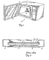
- FIG. 1 illustrates a microwave oven having a door of the type utilized in the present invention.
- the microwave oven 10 shown in Figure 1 includes a front panel 11 and a cooking cavity 12. Lying within the front panel 11 is a choke 13 which is specifically dimensioned and placed so as to absorb microwave energy emitted from the cavity.
- the choke can be of any design known in the art, but typically will have a depth equal to approximately one fourth of the wave length of microwave energy used in the oven, and most commonly will be filled with some type of inert material such as polypropylene. It will be understood that it is not necessary in the present invention that the choke by physically located in the front panel 11. Alternatively the choke can be located in the door frame 14 in a manner well known in the art.
- FIG 2 illustrates the prior art construction of the laminated type oven door.
- Such doors consist of a frame 14 into which is placed a sheet of glass 15 having laminated to it a perforated metal sheet or screen 16 and a layer of plastics 17, such as Mylar or Lexan (R).
- the metal screen 16 and plastics sheet 17 are substantially flat and coplanar with the glass sheet 15.
- the metal screen 16 is generally bonded to the glass sheet 15 by means of an adhesive.
- the adhesive layer may be placed only around the periphery of the screen if desired.
- the metal screen lies generally in close contact with the glass sheet across substantially its entire surface area.
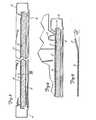
- the metal screen 16 has been substantially modified, as shown best in Figure 5.
- An offset portion is incorporated into the peripheral edge of the screen 16. This can be accomplished in a variety of ways but it is preferred to form a bend in the edge of the screen as illustrated at 19.
- an angle A is indicated between the horizontral and the offset portion 19. This angle may be on the order of approximately 10° to 30°, with an angle of about 15° generally giving good results. However it should be understood that the angle itself is not a critical parameter in the present invention. Rather the more important dimension is that shown by distance B in Figure 3 which is the distance between the screen and the glass when the door is in an assembled condition. This distance should be on the order of 0.0381 cms to 0.254 cms (.01 inches to .100 inches) for best results.
- the angle A can be varied depending on the length of offset portion 19 relative to the total surface area of the screen 16.
- the angle may also be dependent upon the precise method of mounting the screen and the glass into the frame 14. If the angle A is reduced to smaller than about 10° it is likely that there will be insufficient leverage on the screen 16 to cause it to bow sufficiently across its entire surface. On the other hand if the angle A exceeds about 30° it is likely that sufficient bowing will be produced but at the expense of introducing unnecessary stress levels in the metal screen at the offset portion.
- the door frame 14 may be a molded, rollformed, or extruded part and will include a channel 20 for receiving the other door components.
- the door is assembled by placing the glass 15 the metal screen 16 and the plastics sheet 17 into the channel 20 in frame 14 such that the glass forms the outermost surface of the door and the metal screen lies inwardly of the glass toward the oven front panel 11.
- the plastics sheet 17 overlies the metal screen 16 and serves the primary function of improving the cleanability of the door interior by providing a smooth unbroken surface. This prevents food particles and splatters from lodging in the perforations in the metal screen 16.
- the screen 16 is laid upon the glass with offset portions extending away from the glass. As the glass screen and plastics sheet are pressed into the channel 20, the offset portion 19 is caused to flatten against the glass through the pressure of the frame 14. As the offset portion 19 is flattened against the glass the central planar portion of the metal screen is caused to bow or buckle away from the glass, as shown most clearly in Figure 3. In effect, the central planar portion of the metal screen 16 is allowed to "float" free of the glass surface.
- FIG 4 depicts the oven door in a closed position.
- the metal screen 16 is caused to deform in those areas in which it makes contact with the front panel 11. Since the metal screen is free of contact with the glass in that area it is deformable and can conform to the contours of the front panel throughout all areas of contact between the two surfaces. In this manner a much tighter fit around the entire periphery of the front panel is obtained than is possible with the old prior art doors having the metal screen rigidly bonded to the glass.
- the present invention provides a simple, cost effective means of improving the leakage characteristics of modern microwave oven doors, while at the same time allowing their pleasing appearance and esthetics to remain.
Landscapes
- Physics & Mathematics (AREA)
- Electromagnetism (AREA)
- Electric Ovens (AREA)
- Constitution Of High-Frequency Heating (AREA)
Priority Applications (1)
| Application Number | Priority Date | Filing Date | Title |
|---|---|---|---|
| AT81104815T ATE5348T1 (de) | 1980-06-25 | 1981-06-22 | Tuer eines mikrowellenofens mit einem nachgiebigen schirm. |
Applications Claiming Priority (2)
| Application Number | Priority Date | Filing Date | Title |
|---|---|---|---|
| US162983 | 1980-06-25 | ||
| US06/162,983 US4292488A (en) | 1980-06-25 | 1980-06-25 | Microwave oven door having a conformable screen |
Publications (3)
| Publication Number | Publication Date |
|---|---|
| EP0042616A2 EP0042616A2 (en) | 1981-12-30 |
| EP0042616A3 EP0042616A3 (en) | 1982-01-20 |
| EP0042616B1 true EP0042616B1 (en) | 1983-11-16 |
Family
ID=22587943
Family Applications (1)
| Application Number | Title | Priority Date | Filing Date |
|---|---|---|---|
| EP81104815A Expired EP0042616B1 (en) | 1980-06-25 | 1981-06-22 | Microwave oven door having a conformable screen |
Country Status (7)
| Country | Link |
|---|---|
| US (1) | US4292488A (enExample) |
| EP (1) | EP0042616B1 (enExample) |
| JP (1) | JPS5736795A (enExample) |
| AT (1) | ATE5348T1 (enExample) |
| AU (1) | AU538033B2 (enExample) |
| CA (1) | CA1164533A (enExample) |
| DE (1) | DE3161421D1 (enExample) |
Families Citing this family (7)
| Publication number | Priority date | Publication date | Assignee | Title |
|---|---|---|---|---|
| US4384567A (en) * | 1981-09-14 | 1983-05-24 | Mills Products, Inc. | Self-contained window unit for solid fuel burner |
| FR2561359B1 (fr) * | 1984-01-17 | 1986-10-24 | Eurofours Sa | Dispositif de montage d'une vitre pour porte de four |
| JPS614393U (ja) * | 1984-06-15 | 1986-01-11 | シャープ株式会社 | 電子レンジのドアの構造 |
| JPH0332887Y2 (enExample) * | 1986-02-19 | 1991-07-12 | ||
| CA1318014C (en) * | 1989-07-06 | 1993-05-18 | Kevin Smith | Sealing enclosures against electromagnetic interference |
| US20060278629A1 (en) * | 2005-06-08 | 2006-12-14 | Western Industries, Inc. | Electronically controlled outdoor warmer |
| DE102017218832A1 (de) | 2017-10-23 | 2019-04-25 | BSH Hausgeräte GmbH | Tür für ein Haushalts-Mikrowellengerät |
Family Cites Families (11)
| Publication number | Priority date | Publication date | Assignee | Title |
|---|---|---|---|---|
| US3304401A (en) * | 1964-08-28 | 1967-02-14 | Gen Motors Corp | Microwave oven door closure |
| US3666904A (en) * | 1971-04-12 | 1972-05-30 | Bowmar Tic Inc | Microwave oven and door structure for minimizing leakage |
| US3843859A (en) * | 1972-09-27 | 1974-10-22 | Litton Systems Inc | Microwave oven door assembly |
| US3879595A (en) * | 1973-01-08 | 1975-04-22 | Tappan Co | Microwave oven door seal |
| JPS532338Y2 (enExample) * | 1973-12-28 | 1978-01-21 | ||
| US3985993A (en) * | 1974-08-29 | 1976-10-12 | U.S. Philips Corporation | Sealing arrangement in a microwave oven |
| US4206338A (en) * | 1976-02-12 | 1980-06-03 | Mills Products, Inc. | Self-contained window unit for oven doors (common cavity) |
| DE2605699A1 (de) * | 1976-02-13 | 1977-08-25 | Witte & Co Stephan | Mikrowellenherd |
| US4049939A (en) * | 1976-04-29 | 1977-09-20 | Mills Products, Inc. | Microwave and radiant window for oven doors |
| US4081647A (en) * | 1976-05-10 | 1978-03-28 | Roper Corporation | Energy seal for a microwave oven |
| NL7800171A (nl) * | 1977-01-10 | 1978-07-12 | Minnesota Mining & Mfg | Vensterconstructie van microgolfoven. |
-
1980
- 1980-06-25 US US06/162,983 patent/US4292488A/en not_active Expired - Lifetime
-
1981
- 1981-06-08 CA CA000379197A patent/CA1164533A/en not_active Expired
- 1981-06-22 DE DE8181104815T patent/DE3161421D1/de not_active Expired
- 1981-06-22 EP EP81104815A patent/EP0042616B1/en not_active Expired
- 1981-06-22 AT AT81104815T patent/ATE5348T1/de not_active IP Right Cessation
- 1981-06-23 AU AU72074/81A patent/AU538033B2/en not_active Ceased
- 1981-06-25 JP JP9764181A patent/JPS5736795A/ja active Pending
Also Published As
| Publication number | Publication date |
|---|---|
| ATE5348T1 (de) | 1983-12-15 |
| CA1164533A (en) | 1984-03-27 |
| AU7207481A (en) | 1982-01-07 |
| EP0042616A3 (en) | 1982-01-20 |
| DE3161421D1 (en) | 1983-12-22 |
| AU538033B2 (en) | 1984-07-26 |
| US4292488A (en) | 1981-09-29 |
| EP0042616A2 (en) | 1981-12-30 |
| JPS5736795A (enExample) | 1982-02-27 |
Similar Documents
| Publication | Publication Date | Title |
|---|---|---|
| EP0042616B1 (en) | Microwave oven door having a conformable screen | |
| US2958754A (en) | Electronic ovens | |
| CA1318014C (en) | Sealing enclosures against electromagnetic interference | |
| GB2327027A (en) | A door choke arrangement for a microwave oven | |
| US4713511A (en) | Continuous substantially planar microwave oven door assembly | |
| US4146768A (en) | Door for a microwave oven | |
| AU2745184A (en) | Cooker with several hotplates | |
| MY126784A (en) | Microwave oven | |
| US3461517A (en) | Casket gasket | |
| GB2161349A (en) | Microwave oven door | |
| US6241331B1 (en) | Sheet-metal casing with seal | |
| JP2839272B2 (ja) | 高周波加熱装置 | |
| CN210961455U (zh) | 一种密封性好的烹饪锅具 | |
| JPH023676Y2 (enExample) | ||
| DE3475319D1 (en) | Light construction coke oven door | |
| KR102513440B1 (ko) | 발열 인테리어 강판 조립체 | |
| EP0269205A1 (en) | A technique for connecting frame and panel members to produce an RF seal | |
| JP3501480B2 (ja) | 加熱処理装置に用いる扉構造 | |
| JPS6035197Y2 (ja) | 電子レンジ | |
| JPH0733044Y2 (ja) | 電子レンジの扉構造 | |
| DE60008309D1 (de) | Backofen mit gekühlter Tür | |
| JPS6139208Y2 (enExample) | ||
| JPS5935999Y2 (ja) | 高周波加熱装置 | |
| JP2577470B2 (ja) | 加熱調理器の扉 | |
| JPS6136093Y2 (enExample) |
Legal Events
| Date | Code | Title | Description |
|---|---|---|---|
| PUAI | Public reference made under article 153(3) epc to a published international application that has entered the european phase |
Free format text: ORIGINAL CODE: 0009012 |
|
| PUAL | Search report despatched |
Free format text: ORIGINAL CODE: 0009013 |
|
| AK | Designated contracting states |
Designated state(s): AT BE CH DE FR GB IT LU NL SE |
|
| AK | Designated contracting states |
Designated state(s): AT BE CH DE FR GB IT LU NL SE |
|
| 17P | Request for examination filed |
Effective date: 19820305 |
|
| DET | De: translation of patent claims | ||
| ITF | It: translation for a ep patent filed | ||
| GRAA | (expected) grant |
Free format text: ORIGINAL CODE: 0009210 |
|
| AK | Designated contracting states |
Designated state(s): AT BE CH DE FR GB IT LI LU NL SE |
|
| REF | Corresponds to: |
Ref document number: 5348 Country of ref document: AT Date of ref document: 19831215 Kind code of ref document: T |
|
| ET | Fr: translation filed | ||
| REF | Corresponds to: |
Ref document number: 3161421 Country of ref document: DE Date of ref document: 19831222 |
|
| PLBE | No opposition filed within time limit |
Free format text: ORIGINAL CODE: 0009261 |
|
| STAA | Information on the status of an ep patent application or granted ep patent |
Free format text: STATUS: NO OPPOSITION FILED WITHIN TIME LIMIT |
|
| 26N | No opposition filed | ||
| ITTA | It: last paid annual fee | ||
| PGFP | Annual fee paid to national office [announced via postgrant information from national office to epo] |
Ref country code: FR Payment date: 19930316 Year of fee payment: 13 |
|
| PGFP | Annual fee paid to national office [announced via postgrant information from national office to epo] |
Ref country code: SE Payment date: 19930318 Year of fee payment: 13 |
|
| PGFP | Annual fee paid to national office [announced via postgrant information from national office to epo] |
Ref country code: GB Payment date: 19930322 Year of fee payment: 13 |
|
| PGFP | Annual fee paid to national office [announced via postgrant information from national office to epo] |
Ref country code: CH Payment date: 19930323 Year of fee payment: 13 |
|
| PGFP | Annual fee paid to national office [announced via postgrant information from national office to epo] |
Ref country code: BE Payment date: 19930326 Year of fee payment: 13 |
|
| PGFP | Annual fee paid to national office [announced via postgrant information from national office to epo] |
Ref country code: LU Payment date: 19930401 Year of fee payment: 13 Ref country code: AT Payment date: 19930401 Year of fee payment: 13 |
|
| PGFP | Annual fee paid to national office [announced via postgrant information from national office to epo] |
Ref country code: NL Payment date: 19930630 Year of fee payment: 13 Ref country code: DE Payment date: 19930630 Year of fee payment: 13 |
|
| EPTA | Lu: last paid annual fee | ||
| PG25 | Lapsed in a contracting state [announced via postgrant information from national office to epo] |
Ref country code: LU Free format text: LAPSE BECAUSE OF NON-PAYMENT OF DUE FEES Effective date: 19940622 Ref country code: GB Effective date: 19940622 Ref country code: AT Effective date: 19940622 |
|
| PG25 | Lapsed in a contracting state [announced via postgrant information from national office to epo] |
Ref country code: SE Effective date: 19940623 |
|
| PG25 | Lapsed in a contracting state [announced via postgrant information from national office to epo] |
Ref country code: LI Effective date: 19940630 Ref country code: CH Effective date: 19940630 Ref country code: BE Effective date: 19940630 |
|
| BERE | Be: lapsed |
Owner name: LITTON SYSTEMS INC. Effective date: 19940630 |
|
| PG25 | Lapsed in a contracting state [announced via postgrant information from national office to epo] |
Ref country code: NL Effective date: 19950101 |
|
| EUG | Se: european patent has lapsed |
Ref document number: 81104815.6 Effective date: 19950110 |
|
| GBPC | Gb: european patent ceased through non-payment of renewal fee |
Effective date: 19940622 |
|
| NLV4 | Nl: lapsed or anulled due to non-payment of the annual fee | ||
| PG25 | Lapsed in a contracting state [announced via postgrant information from national office to epo] |
Ref country code: FR Effective date: 19950228 |
|
| REG | Reference to a national code |
Ref country code: CH Ref legal event code: PL |
|
| PG25 | Lapsed in a contracting state [announced via postgrant information from national office to epo] |
Ref country code: DE Effective date: 19950301 |
|
| EUG | Se: european patent has lapsed |
Ref document number: 81104815.6 |
|
| REG | Reference to a national code |
Ref country code: FR Ref legal event code: ST |