EP0042216A2 - Brennstoffreaktor - Google Patents
Brennstoffreaktor Download PDFInfo
- Publication number
- EP0042216A2 EP0042216A2 EP81302229A EP81302229A EP0042216A2 EP 0042216 A2 EP0042216 A2 EP 0042216A2 EP 81302229 A EP81302229 A EP 81302229A EP 81302229 A EP81302229 A EP 81302229A EP 0042216 A2 EP0042216 A2 EP 0042216A2
- Authority
- EP
- European Patent Office
- Prior art keywords
- fuel
- inlet
- cone
- inner shell
- shell
- Prior art date
- Legal status (The legal status is an assumption and is not a legal conclusion. Google has not performed a legal analysis and makes no representation as to the accuracy of the status listed.)
- Granted
Links
Images


Classifications
-
- F—MECHANICAL ENGINEERING; LIGHTING; HEATING; WEAPONS; BLASTING
- F23—COMBUSTION APPARATUS; COMBUSTION PROCESSES
- F23C—METHODS OR APPARATUS FOR COMBUSTION USING FLUID FUEL OR SOLID FUEL SUSPENDED IN A CARRIER GAS OR AIR
- F23C7/00—Combustion apparatus characterised by arrangements for air supply
- F23C7/02—Disposition of air supply not passing through burner
- F23C7/06—Disposition of air supply not passing through burner for heating the incoming air
-
- F—MECHANICAL ENGINEERING; LIGHTING; HEATING; WEAPONS; BLASTING
- F23—COMBUSTION APPARATUS; COMBUSTION PROCESSES
- F23C—METHODS OR APPARATUS FOR COMBUSTION USING FLUID FUEL OR SOLID FUEL SUSPENDED IN A CARRIER GAS OR AIR
- F23C3/00—Combustion apparatus characterised by the shape of the combustion chamber
Definitions
- the present invention relates to fuel reactors.
- a high intensity burner including an outer shell which is of generally circular cross-section, and usually frusto-conical, with a fuel inlet being provided at one end, usually the lower end so that fuel is projected axially into the shell.
- An inner shell is mounted within the outer shell, with its lower end spaced from the inlet end of the outer shell, and its peripheral wall spaced from the wall of the outer shell to provide an annular space into which combustion air is forced by way of a tangential combustion air inlet.
- the combustion air swirls downwardly, and combines with the fuel that is ignited, and the products of combustion are discharged through a discharge nozzle at the upper end of the inner shell.
- a fuel reactor comprising a generally circular cross-section elongate outer shell, closed at one axial end, a fuel inlet at said one axial end adapted to project fuel axially into said outer shell, an inner shell mounted within said outer shell to define an annular space therebetween, the inner and outer shells being connected together at a discharge end of the inner shell, the other end of the inner shell being open and axially spaced from the closed end of the outer shell, a tangential combustion air inlet connected to the annular space at an axial location spaced from said other end of the inner shell, a discharge nozzle mounted on the discharge end of the inner shell and at least one opening in the inner shell adjacent the discharge nozzle communicating with the annular space, to allow some of the air to flow onto the exterior of the discharge nozzle to cool it.
- these openings Preferably there are a plurality of these openings, for example six, in the inner shell and these are circumferentially spaced around the nozzle.
- such openings are in the form of tangential slots in the inner shell, these being angled in the same sense as the tangential combustion air inlet, whereby a portion of the air swirling in the annular space as a result of entering via the air inlet is scooped up by the slots and flows readily onto the exterior surface of the nozzle.
- the outer shell may be provided with a radially inwardly directed support ring at the end which is remote from the fuel inlet while the inner shell is provided with a radially outwardly directed flange at its discharge end, the flange abutting the support ring to connect the inner and outer shells. If the inner axial face of the flange engages the outer axial face of the support ring, the inner shell, together with the nozzle can readily be removed by lifting upwardly. This is greatly facilitated if the inner shell is of frusto-conical form,diverging towards the outlet or discharge end.
- the outer shell is advantageously closed by a base plate having a fuel inlet aperture therein and a first frusto-conical inlet cone is mounted on this base plate to surround the fuel inlet aperture, a second frusto-conical inlet cone being mounted coaxially with the first and spaced therefrom, whereby a portion of the combustion air can flow through the annular space between the first and second inlet cones, to premix with fuel entering at the fuel inlet aperture.
- a particularly stable arrangement can be provided when the second inlet cone is mounted on the first inlet cone by means of a plurality of circumferentially spaced vanes, which preferably : extend in radial planes with respect to the axis of the cores.
- the second inlet cone then preferably overlaps the first inlet cone, so that the portion of combustion air has an axial component of velocity as it passes through the annular space to enter the second inlet cone.
- a pilot burner may extend axially through the inlet aperture to a location within the first inlet cone and it has been found that the pilot flame, in such an arrangement, is very stable for the full range of combustion air flows.
- the first cone includes at least one flame arrestor screen and a spark igniter and/or a flame detector, for example a ultra-violet flame detector may be provided within the first cone.
- a spark igniter and/or a flame detector for example a ultra-violet flame detector may be provided within the first cone.
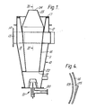
- a fuel reactor comprising an outer circular cross-section shell indicated by the reference numeral 10 having a frusto-conical lower portion 11 surmounted by a cylindrical portion 12.
- a tangentially arranged combustion air inlet 13 is connected to the lower part of the cylindrical portion 12 and terminates in a fixing flange 14 for securing to a suitable blower discharge.
- the outer shell cylindrical portion 12 has a radially inwardly directed support ring 15 welded thereto.
- An inner shell 16, of generally frusto-conical upwardly divergent form has a radially outwardly extending flange 17 which rests on and is supported by the ring 15 of the outer shell, the ring 15 and flange 17 together closing the annular space 18 formed between the inner and outer shells 11 and 16.
- a fuel inlet assembly is indicated by the general reference numeral 21 and will be described in more detail later. Suffice it to say, for the present, the fuel inlet assembly 21 projects fuel, usually gaseous fuel, into the inner shell 16 along the axis thereof.
- a spider 22 maintains the lower end 19 of the inner shell 16 away from the wall of the outer/shell 11, and permits combustion air, which is blown in through the tangential combustion air inlet 13, to swirl downwardly and act as the combustion air for the fuel.
- the inner shell 16 is provided with a fishmouth discharge nozzle 23 which may be made of ceramic material and is wider in one direction than the other, as can be seen in particular from Figure 2 and also from Figures 1 and 3..
- the shape of this nozzle is such that the products of combustion fan out as they leave the outlet orifice 24 at the upper end of the nozzle 23.
- the wall of the inner shell 16 is provided with six equi-angularly circumferentially spaced openings in the form of slots 25, the construction of which can be seen more readily from Figure 4.
- the slots 25 are shown as punched out from the metal of the inner shell 16. They could, however, be formed by cutting holes in the shell 16 and providing an overlying deflector plate.
- the slots 25 are tangentially disposed in the same sense as the tangential disposition of the combustion air inlet 13, so that a proportion of the air which is blown in at 13 will be "scooped" by the slots 25 and projected onto the exterior surface of the nozzle 23 thus cooling it significantly. It has been found that heat conduction and radiation to the outer surfaces of the reactor are very significantly reduced so that the reactors may be expected to have a longer operational life and greater mechanical integrity than known reactors of this type.
- the base plate 20 is provided with a central fuel inlet opening 50 over which is fitted a T cross-section fuel inlet pipe 51 connectable, by flange 52, to a source of fuel. Extending along the cross of the T is the feed tube 53 of a pilot burner 54.
- an inner cone 55 of upwardly convergent frusto-conical form, the lower edge of this cone 55 being secured to the base plate 20.
- a support plate 56 which actually carries the pilot burner 54.
- a perforated flame arrestor plate 57 is provided.
- an igniter for example a spark igniter, 59, a flame rod 60 and a UV detector 61', the tips of these all extending above the flame arrestor plate 57.
- vanes 62 Welded to the exterior wall of the inner cone 55 are four equi-angularly spaced vanes 62, the vanes 62 each extendinc in a radial plane with respect to the axis of the inner cone. Coaxially mounted with respect to the inner cone is an outer cone 63 which is welded to the vanes 62 and provides therewith an annular air space 64.
- the pilot burner can be ignited, when gas is applied through the pipe 53 by means of the-igniter 59.
- the main gas supply is fed in through flange 52 and pipe 51, it passes through opening 50 and into the inner cone and is ignited by the pilot flame.
- Combustion air for the pilot flame is-provided by air flowing radially inwardly through the perforations in the upper portion 58 of the inner cone.
- Some combustion of air for the flame of the main burner is fed in via the annular space 64 between the lower edge of the outer cone and the upper edge of the lower or inner cone. This will only be a proportion of the total amount of combustion air for the main burner, the remaining combustion air arriving in the space between the top edge of the outer cone 63 and the lower edge 19 of the inner shell 16.
Landscapes
- Engineering & Computer Science (AREA)
- Chemical & Material Sciences (AREA)
- Combustion & Propulsion (AREA)
- Mechanical Engineering (AREA)
- General Engineering & Computer Science (AREA)
- Thermal Sciences (AREA)
- Physics & Mathematics (AREA)
- Physical Or Chemical Processes And Apparatus (AREA)
- Fuel-Injection Apparatus (AREA)
- Pre-Mixing And Non-Premixing Gas Burner (AREA)
- Pressure-Spray And Ultrasonic-Wave- Spray Burners (AREA)
- Gas Burners (AREA)
- Glass Compositions (AREA)
- Gas Separation By Absorption (AREA)
- Hydrogen, Water And Hydrids (AREA)
- Surface Treatment Of Glass (AREA)
- Manufacture, Treatment Of Glass Fibers (AREA)
- Absorbent Articles And Supports Therefor (AREA)
Priority Applications (1)
| Application Number | Priority Date | Filing Date | Title |
|---|---|---|---|
| AT81302229T ATE6959T1 (de) | 1980-06-17 | 1981-05-19 | Brennstoffreaktor. |
Applications Claiming Priority (2)
| Application Number | Priority Date | Filing Date | Title |
|---|---|---|---|
| GB8019826A GB2078363B (en) | 1980-06-17 | 1980-06-17 | Fuel reactor |
| GB8019826 | 1980-06-17 |
Publications (3)
| Publication Number | Publication Date |
|---|---|
| EP0042216A2 true EP0042216A2 (de) | 1981-12-23 |
| EP0042216A3 EP0042216A3 (en) | 1982-10-20 |
| EP0042216B1 EP0042216B1 (de) | 1984-04-04 |
Family
ID=10514111
Family Applications (1)
| Application Number | Title | Priority Date | Filing Date |
|---|---|---|---|
| EP81302229A Expired EP0042216B1 (de) | 1980-06-17 | 1981-05-19 | Brennstoffreaktor |
Country Status (17)
| Country | Link |
|---|---|
| US (1) | US4373899A (de) |
| EP (1) | EP0042216B1 (de) |
| JP (1) | JPS5762316A (de) |
| KR (1) | KR850001185B1 (de) |
| AT (1) | ATE6959T1 (de) |
| AU (1) | AU539400B2 (de) |
| BR (1) | BR8103817A (de) |
| CA (1) | CA1159355A (de) |
| DE (1) | DE3162943D1 (de) |
| EG (1) | EG15178A (de) |
| ES (1) | ES8204130A1 (de) |
| GB (1) | GB2078363B (de) |
| IN (1) | IN156161B (de) |
| MA (1) | MA19162A1 (de) |
| NZ (1) | NZ197187A (de) |
| SU (1) | SU1179946A3 (de) |
| ZA (1) | ZA813436B (de) |
Families Citing this family (4)
| Publication number | Priority date | Publication date | Assignee | Title |
|---|---|---|---|---|
| RU2143639C1 (ru) * | 1998-01-12 | 1999-12-27 | Клепиков Николай Степанович | Топочное устройство |
| RU2341728C1 (ru) * | 2007-04-09 | 2008-12-20 | Открытое акционерное общество "Научно-производственное объединение по исследованию и проектированию энергетического оборудования им. И.И. Ползунова" (ОАО "НПО ЦКТИ") | Топочное устройство |
| RU2373457C2 (ru) * | 2007-12-03 | 2009-11-20 | Закрытое акционерное общество "СибКОТЭС" | Топка парогенератора |
| US20240263786A1 (en) * | 2023-02-02 | 2024-08-08 | Pratt & Whitney Canada Corp. | Central air passage with radial fuel distributor |
Family Cites Families (7)
| Publication number | Priority date | Publication date | Assignee | Title |
|---|---|---|---|---|
| DE137751C (de) * | ||||
| US2727566A (en) * | 1943-03-13 | 1955-12-20 | Claude A Bonvillian | Apparatus for the combustion of fuel |
| US2958194A (en) * | 1951-09-24 | 1960-11-01 | Power Jets Res & Dev Ltd | Cooled flame tube |
| NL113358C (de) * | 1957-02-18 | |||
| GB851125A (en) * | 1957-11-29 | 1960-10-12 | Gen Motors Corp | Combustion chamber of a gas turbine engine |
| US3720497A (en) * | 1971-06-03 | 1973-03-13 | Black Sivalls & Bryson Inc | Gas burner apparatus |
| US3846066A (en) * | 1973-05-24 | 1974-11-05 | Black Sivalls & Bryson Inc | Fuel burner apparatus |
-
1980
- 1980-06-17 GB GB8019826A patent/GB2078363B/en not_active Expired
-
1981
- 1981-04-24 US US06/257,273 patent/US4373899A/en not_active Expired - Fee Related
- 1981-04-30 CA CA000376629A patent/CA1159355A/en not_active Expired
- 1981-05-19 DE DE8181302229T patent/DE3162943D1/de not_active Expired
- 1981-05-19 AT AT81302229T patent/ATE6959T1/de not_active IP Right Cessation
- 1981-05-19 EP EP81302229A patent/EP0042216B1/de not_active Expired
- 1981-05-21 ZA ZA00813436A patent/ZA813436B/xx unknown
- 1981-05-22 IN IN327/DEL/81A patent/IN156161B/en unknown
- 1981-05-25 NZ NZ197187A patent/NZ197187A/en unknown
- 1981-06-01 MA MA19371A patent/MA19162A1/fr unknown
- 1981-06-10 AU AU71470/81A patent/AU539400B2/en not_active Ceased
- 1981-06-15 ES ES503046A patent/ES8204130A1/es not_active Expired
- 1981-06-16 SU SU813296449A patent/SU1179946A3/ru active
- 1981-06-16 JP JP56091627A patent/JPS5762316A/ja active Pending
- 1981-06-16 EG EG81333A patent/EG15178A/xx active
- 1981-06-16 KR KR1019810002187A patent/KR850001185B1/ko not_active Expired
- 1981-06-16 BR BR8103817A patent/BR8103817A/pt unknown
Also Published As
| Publication number | Publication date |
|---|---|
| GB2078363A (en) | 1982-01-06 |
| ES503046A0 (es) | 1982-04-01 |
| NZ197187A (en) | 1985-05-31 |
| AU7147081A (en) | 1981-12-24 |
| MA19162A1 (fr) | 1981-12-31 |
| US4373899A (en) | 1983-02-15 |
| ZA813436B (en) | 1982-06-30 |
| KR850001185B1 (ko) | 1985-08-19 |
| ATE6959T1 (de) | 1984-04-15 |
| EP0042216B1 (de) | 1984-04-04 |
| BR8103817A (pt) | 1982-03-09 |
| ES8204130A1 (es) | 1982-04-01 |
| JPS5762316A (en) | 1982-04-15 |
| IN156161B (de) | 1985-06-01 |
| AU539400B2 (en) | 1984-09-27 |
| EP0042216A3 (en) | 1982-10-20 |
| DE3162943D1 (en) | 1984-05-10 |
| KR830006629A (ko) | 1983-09-28 |
| EG15178A (en) | 1986-06-30 |
| GB2078363B (en) | 1984-03-07 |
| CA1159355A (en) | 1983-12-27 |
| SU1179946A3 (ru) | 1985-09-15 |
Similar Documents
| Publication | Publication Date | Title |
|---|---|---|
| US5649822A (en) | Gas burner | |
| US5140814A (en) | Exhaust gas system with an particulate filter and a regenerating burner | |
| EP0378505B1 (de) | Brenner und Brennstoffinjektor-Anordnung | |
| EP0550218B1 (de) | Brennkammer einer Gasturbine | |
| US5193346A (en) | Premixed secondary fuel nozzle with integral swirler | |
| US6026645A (en) | Fuel/air mixing disks for dry low-NOx combustors | |
| US4244349A (en) | Portable forced air heater | |
| US5846068A (en) | Flare apparatus and methods | |
| US6036481A (en) | Burner with flame retainer insert | |
| GB1601916A (en) | Geyseric burner assembly and method for combusting fuels | |
| US5490778A (en) | Burner | |
| JPS62129613A (ja) | 燃料バ−ナの火炎保持ヘツド装置および燃料バ−ナ | |
| EP0042217B1 (de) | Brennstoffzufuhreinrichtung für Brennstoffreaktoren | |
| JP2001510885A (ja) | 燃焼設備用特にガスタービン燃焼器用のバーナ装置 | |
| US4846670A (en) | Combustion device | |
| US3529917A (en) | Air-mixing device for fuel burner | |
| US20040055270A1 (en) | Premixed burner with profiled air mass stream, gas turbine and process for burning fuel in air | |
| EP0042216B1 (de) | Brennstoffreaktor | |
| CA2141754A1 (en) | Burner for the combustion of fuel | |
| CN110260310A (zh) | 一种全预混燃烧器 | |
| US4362021A (en) | Gas turbine engine fuel injectors | |
| US20210270457A1 (en) | Energy saving jet burner | |
| EP0451923A2 (de) | Brenner | |
| US4674974A (en) | Pot burner for liquid fuel | |
| JPH05606B2 (de) |
Legal Events
| Date | Code | Title | Description |
|---|---|---|---|
| PUAI | Public reference made under article 153(3) epc to a published international application that has entered the european phase |
Free format text: ORIGINAL CODE: 0009012 |
|
| AK | Designated contracting states |
Designated state(s): AT BE CH DE FR GB IT LU NL SE |
|
| PUAL | Search report despatched |
Free format text: ORIGINAL CODE: 0009013 |
|
| AK | Designated contracting states |
Designated state(s): AT BE CH DE FR GB IT LU NL SE |
|
| 17P | Request for examination filed |
Effective date: 19821106 |
|
| ITF | It: translation for a ep patent filed | ||
| GRAA | (expected) grant |
Free format text: ORIGINAL CODE: 0009210 |
|
| AK | Designated contracting states |
Designated state(s): AT BE CH DE FR GB IT LI LU NL SE |
|
| REF | Corresponds to: |
Ref document number: 6959 Country of ref document: AT Date of ref document: 19840415 Kind code of ref document: T |
|
| REF | Corresponds to: |
Ref document number: 3162943 Country of ref document: DE Date of ref document: 19840510 |
|
| PGFP | Annual fee paid to national office [announced via postgrant information from national office to epo] |
Ref country code: FR Payment date: 19840528 Year of fee payment: 4 Ref country code: AT Payment date: 19840528 Year of fee payment: 4 |
|
| PG25 | Lapsed in a contracting state [announced via postgrant information from national office to epo] |
Ref country code: LU Free format text: LAPSE BECAUSE OF NON-PAYMENT OF DUE FEES Effective date: 19840531 |
|
| PGFP | Annual fee paid to national office [announced via postgrant information from national office to epo] |
Ref country code: DE Payment date: 19840615 Year of fee payment: 4 Ref country code: CH Payment date: 19840615 Year of fee payment: 4 |
|
| ET | Fr: translation filed | ||
| PGFP | Annual fee paid to national office [announced via postgrant information from national office to epo] |
Ref country code: SE Payment date: 19840630 Year of fee payment: 4 Ref country code: BE Payment date: 19840630 Year of fee payment: 4 |
|
| PLBE | No opposition filed within time limit |
Free format text: ORIGINAL CODE: 0009261 |
|
| STAA | Information on the status of an ep patent application or granted ep patent |
Free format text: STATUS: NO OPPOSITION FILED WITHIN TIME LIMIT |
|
| 26N | No opposition filed | ||
| PG25 | Lapsed in a contracting state [announced via postgrant information from national office to epo] |
Ref country code: AT Effective date: 19850519 |
|
| PG25 | Lapsed in a contracting state [announced via postgrant information from national office to epo] |
Ref country code: SE Effective date: 19850520 |
|
| PG25 | Lapsed in a contracting state [announced via postgrant information from national office to epo] |
Ref country code: LI Effective date: 19850531 Ref country code: CH Effective date: 19850531 |
|
| PGFP | Annual fee paid to national office [announced via postgrant information from national office to epo] |
Ref country code: NL Payment date: 19850531 Year of fee payment: 5 |
|
| REG | Reference to a national code |
Ref country code: CH Ref legal event code: PL |
|
| PG25 | Lapsed in a contracting state [announced via postgrant information from national office to epo] |
Ref country code: BE Effective date: 19860531 |
|
| BERE | Be: lapsed |
Owner name: BS & B ENGINEERING CY INC. Effective date: 19860531 |
|
| PG25 | Lapsed in a contracting state [announced via postgrant information from national office to epo] |
Ref country code: NL Effective date: 19861201 |
|
| NLV4 | Nl: lapsed or anulled due to non-payment of the annual fee | ||
| GBPC | Gb: european patent ceased through non-payment of renewal fee | ||
| PG25 | Lapsed in a contracting state [announced via postgrant information from national office to epo] |
Ref country code: FR Free format text: LAPSE BECAUSE OF NON-PAYMENT OF DUE FEES Effective date: 19870130 |
|
| PG25 | Lapsed in a contracting state [announced via postgrant information from national office to epo] |
Ref country code: DE Effective date: 19870203 |
|
| REG | Reference to a national code |
Ref country code: FR Ref legal event code: ST |
|
| PG25 | Lapsed in a contracting state [announced via postgrant information from national office to epo] |
Ref country code: GB Effective date: 19881118 |
|
| EUG | Se: european patent has lapsed |
Ref document number: 81302229.0 Effective date: 19860728 |