EP0042044A1 - Axial-flow compressor with displaced surge limit - Google Patents
Axial-flow compressor with displaced surge limit Download PDFInfo
- Publication number
- EP0042044A1 EP0042044A1 EP81102534A EP81102534A EP0042044A1 EP 0042044 A1 EP0042044 A1 EP 0042044A1 EP 81102534 A EP81102534 A EP 81102534A EP 81102534 A EP81102534 A EP 81102534A EP 0042044 A1 EP0042044 A1 EP 0042044A1
- Authority
- EP
- European Patent Office
- Prior art keywords
- axial compressor
- compressor according
- flow
- housing
- sleepers
- Prior art date
- Legal status (The legal status is an assumption and is not a legal conclusion. Google has not performed a legal analysis and makes no representation as to the accuracy of the status listed.)
- Granted
Links
Images


Classifications
-
- F—MECHANICAL ENGINEERING; LIGHTING; HEATING; WEAPONS; BLASTING
- F04—POSITIVE - DISPLACEMENT MACHINES FOR LIQUIDS; PUMPS FOR LIQUIDS OR ELASTIC FLUIDS
- F04D—NON-POSITIVE-DISPLACEMENT PUMPS
- F04D19/00—Axial-flow pumps
- F04D19/02—Multi-stage pumps
- F04D19/028—Layout of fluid flow through the stages
-
- F—MECHANICAL ENGINEERING; LIGHTING; HEATING; WEAPONS; BLASTING
- F04—POSITIVE - DISPLACEMENT MACHINES FOR LIQUIDS; PUMPS FOR LIQUIDS OR ELASTIC FLUIDS
- F04D—NON-POSITIVE-DISPLACEMENT PUMPS
- F04D29/00—Details, component parts, or accessories
- F04D29/40—Casings; Connections of working fluid
- F04D29/52—Casings; Connections of working fluid for axial pumps
- F04D29/54—Fluid-guiding means, e.g. diffusers
- F04D29/541—Specially adapted for elastic fluid pumps
- F04D29/545—Ducts
- F04D29/547—Ducts having a special shape in order to influence fluid flow
Definitions
- the invention relates to a single-stage or multi-stage axial compressor with axially one behind the other, combined into stages guide vane and rotor blade rings, and with one or more protruding from the inner surface of the housing surrounding the vane rings, circumferential around the axis, the type of a threshold Stairs are graduated.
- Such a device is described in DE-PS 809 842.
- the changes in the inside diameter required in the direction of flow are carried out in this device by gradual narrowing.
- the thresholds mentioned are present both on the inside of the housing and on the outside of the rotor.
- the threshold surfaces are preferably each cylindrical or conical.
- the flow guidance is to be improved by the thresholds in such a way that the risk of the flow separating at the impeller outside and at the stator inside is reduced when the axial speed is shifted.
- Such a shift in the axial speed is then - according to the cited patent - under certain circumstances forced to avoid difficulties with regard to the Mach number at high peripheral speeds. This indicates that the known device should make it possible to improve the flow, particularly when shifting to high speeds.
- the primary aim is not to improve the design of the compressor, but to enlarge the working area. As experience shows, it is necessary to increase the flow in the axial direction at the blade tip if, for. B. the peripheral speed is reduced.
- DE-AS 2 351 308 To avoid the stall, it is also known (DE-AS 2 351 308) to arrange a profiled ring which is arranged in front of a rotor blade ring and is concentric with the machine axis, the outer ring surface of which forms an annular channel converging in the flow direction with the housing wall.
- the proposed solution according to DE-AS 2 351 308 is indeed feasible, but in practice means relatively high additional construction costs, since the ring can be difficult to install in the housing if the other structural requirements are taken into account. The efficiency losses due to the additional, friction-generating surface and the so-called flow wake are also not to be underestimated.
- the construction according to the invention therefore has the advantages that it can be installed economically and at a reasonable cost, and that, in theory, it causes only a slight loss in efficiency which could not be measured in practice.
- the device according to DE-OS 2 446 512 is unsuitable in the case of the axially compressed type mentioned at the beginning of the invention, in order to stabilize the surge limit in the lower delivery range, in particular because the detachment that first occurs on the rotor blade grille cannot be corrected, but also on the other hand Because of the completely different blade configuration of a compressor with axial blading, the principle is not transferable.
- An essential criterion for the design of the object according to the invention is that, under normal load, the sleepers to be installed do not narrow the cross section so much that normal operation is significantly impeded.
- the sleepers should preferably constrict the free overall cross-section of the housing only to an amount between 80-99%, preferably between 95-99%, of the cross-sectional area existing before the threshold.
- the inner contour of the compressor housing can be assigned a certain average taper, which is related to the compression to be achieved. It is proposed, when using the sleepers according to the invention, to approximate the base points of the sleepers to a conical jacket describing the mean taper of the inner wall of the housing It is also possible to deviate from this position, whereby wind tunnel and standing tests can provide the expert with hints for improvement.
- the threshold height can then preferably also be varied in the further course of the flow, in particular increasing successively.
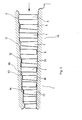
- the exemplary embodiments of multi-stage axial compressors shown in FIGS. 1 and 2 have guide vane and rotor blade rings arranged one after the other and combined to form stages 1, 2, 3.
- the guide blades 4, 6 are connected downstream of the moving blades 5, 7.
- a guide ring 8 with pivotable blades for regulating the throughput quantity is arranged in front of the first rotor blade ring.
- the blades 4 to 7 are also partially pivotable and connected to corresponding adjustment devices.
- sleepers 12, 13, 14 are provided on the opposite inner wall 11 of the housing, which protrude inward and circumferentially around the axis from the inner surface of the housing surrounding the blade rings.
- the sleepers are stepped in the direction of flow in the manner of a staircase, constricting the free overall cross-section of the housing from step to step by 1-5% of the cross-sectional area in front of the threshold.
- Each threshold 12 - 14 is arranged directly in front of a moving blade, in the present case designated with the numbers 15, 16, 17, the streamlines being compressed in operation in the area of the moving blade tips.
- the outer contour of the sleepers i. H. the rising surface 18 rounded convex curved.
- the curve of curvature is composed of circular and / or parabolic arcs. The curvature is intended to prevent flow breaks, turbulence and similar disturbances in the flow from occurring.
- the narrowing of the overall cross section through the thresholds 12, 13, 14 is not so great that an excessive flow constriction occurs in normal operation, which is also undesirable.
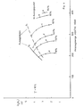
- FIG. 4 shows various characteristic curves which were measured on an axial compressor with an output of approximately 400,000 m 3 / h.
- the flow channel with a tapered but smooth inner surface was used once; on the other hand, a flow channel was used which had the thresholds according to the invention.
- the design point for both compressors was a pressure ratio of approximately 4.4 and a nominal delivery rate of approximately 375,000 m 3 / h.
- the surge limit in the original form, designated G1 was significantly less favorable than when using sleepers according to the invention. This resulted in a curve G2.
- the characteristic curves a ... f were measured at different guide vane positions, the percentages relating to the adjustment range of the guide vanes, ie defined by the path of the vane adjustment mechanism.
- the nominal speed was around 3,000 rpm.
- the base points of the thresholds 12-14 each lie on one medium conicity of the conical casing describing the inner wall of the housing. This shape is relatively easy to manufacture and brings a defined compression performance.
- the blades In order to allow the blades to be precisely fitted within the housing, the blades are turned over at their tips in a cylindrical or conical manner. This gives them exactly the same distance from the inner wall of the housing, the gradation through the threshold allowing a defined flow gain that is the same for all individual blades.
Landscapes
- Engineering & Computer Science (AREA)
- Physics & Mathematics (AREA)
- Fluid Mechanics (AREA)
- Mechanical Engineering (AREA)
- General Engineering & Computer Science (AREA)
- Structures Of Non-Positive Displacement Pumps (AREA)
Abstract
Description
Die Erfindung betrifft einen ein- oder mehrstufigen Axialverdichter mit axial hintereinander angeordneten, zu Stufen zusammengefaßten Leitschaufel- und Laufschaufelkränzen, und mit einer oder mehreren aus der Innenfläche des die Schaufelkränze umgebenden Gehäuses nach innen vorstehenden, zirkumferential um die Achse verlaufenden Schwellen, die nach Art einer Treppe abgestuft sind.The invention relates to a single-stage or multi-stage axial compressor with axially one behind the other, combined into stages guide vane and rotor blade rings, and with one or more protruding from the inner surface of the housing surrounding the vane rings, circumferential around the axis, the type of a threshold Stairs are graduated.
Eine solche Vorrichtung ist in der DE-PS 809 842 beschrieben. Die in Strömungsrichtung erforderlichen Veränderungen des Innendurchmessers sind bei dieser Vorrichtung durch stufenweise Einengung durchgeführt. Dabei sind die genannten Schwellen sowohl an der Innenseite des Gehäuses als auch an der Außenseite des Rotors vorhanden. Die Schwellenoberflächen sind vorzugsweise jeweils zylindrisch oder konisch geführt. Die Strömungsführung soll durch die Schwellen dahingehend verbessert werden, daß die Ablösungsgefahr der Strömung beim Laufrad außen und beim Leitrad innen bei Verschiebung der Axialgeschwindigkeit verringert wird. Zu einer solchen Verschiebung der Axialgeschwindigkeit ist man - nach Aussage der genannten Patentschrift - dann unter Umständen gezwungen, um bei hohen Umfangsgeschwindigkeiten Schwierigkeiten hinsichtlich der Machzahl zu vermeiden. Damit ist angedeutet, daß die bekannte Vorrichtung insbesondere bei Verschiebung zu hohen Drehzahlen eine Verbesserung der Strömung ermöglichen sollte.Such a device is described in DE-PS 809 842. The changes in the inside diameter required in the direction of flow are carried out in this device by gradual narrowing. The thresholds mentioned are present both on the inside of the housing and on the outside of the rotor. The threshold surfaces are preferably each cylindrical or conical. The flow guidance is to be improved by the thresholds in such a way that the risk of the flow separating at the impeller outside and at the stator inside is reduced when the axial speed is shifted. Such a shift in the axial speed is then - according to the cited patent - under certain circumstances forced to avoid difficulties with regard to the Mach number at high peripheral speeds. This indicates that the known device should make it possible to improve the flow, particularly when shifting to high speeds.
Die Zeichnung der genannten Patentschrift und die entsprechende Beschreibung zeigen einen Teil des Strömungskanals eines Axialverdichters. Es ist daraus ersichtlich, daß in Strömungsrichtung sich der Strömungskanal jeweils im Fußbereich vor den nachfolgenden Leit- und Laufschaufeln verengt. Dazu sind Schwellen in der Umfangslinie sowohl des Gehäuses als auch des Rotors ausgebildet. Diese Anordnung ist nicht geeignet, die Pumpgrenze des Verdichters, d. h.. das Abreißen der Strömung an den Schaufeln bei kleineren Fördermengen, zu verhindern. Mit kleiner werdenden Durchsätzen, insbesondere bei Verzögerungsgittern, steigt die Tendenz zur Ablösung der Strömung auf der Saugseite der Schaufeln. Diese Abreißneigung ist bei Gittern beliebiger Form festzustellen; sie ist unabhängig von der Bewegung des Gitters, wenn die Strömung relativ zum Gitter betrachtet wird. Die Ablösungstendenz ist also bei Leit- und Laufschaufeln von Axialverdichtern vorhanden. Außerdem tritt die Ablösung nicht an allen Schaufeln einer Verdichterstufe gleichzeitig ein, sondern zunächst nur an einzelnen oder an mehreren Stellen des Laufschaufelgitters (vgl. Darstellung auf S. 478/479 des Buches ECKERT/SCHNELL "Axial- und Radialkompressoren", Springer-Verlag 1961).The drawing of the mentioned patent specification and the corresponding description show a part of the flow channel of an axial compressor. It can be seen from this that the flow channel narrows in the foot area in front of the subsequent guide vanes and rotor blades. For this purpose, thresholds are formed in the circumferential line of both the housing and the rotor. This arrangement is not suitable, ie the surge limit of the compressor. to prevent the flow from breaking off at the blades with smaller flow rates. With decreasing throughputs, especially with delay grids, the tendency for the flow to separate on the suction side of the blades increases. This tendency to tear off can be determined with gratings of any shape; it is independent of the movement of the grid when the flow is viewed relative to the grid. The tendency to detach is therefore present in the guide and rotor blades of axial compressors. In addition, the detachment does not occur simultaneously on all the blades of a compressor stage, but initially only at individual or at several points on the rotor blade grille (see illustration on pages 478/479 of the book ECKERT / SCHNELL "Axial- und Radialkompressoren", Springer-Verlag 1961 ).
Es besteht aber auch die Möglichkeit, daß diese Erscheinung, wenn sie einmal begonnen hat, sofort verstärkt wird und das ganze Strömungssystem im Verdichter dadurch aus dem Gleichgewicht kommt, d. h. das Arbeiten des Verdichters wird labil. Diesen Vorgang bezeichnet man allgemein mit "Pumpen", die Grenze, bei der das "Pumpen" eintritt, als "Pumpgrenze".However, there is also the possibility that this phenomenon, once it has started, is immediately amplified and the entire flow system in the compressor is thereby out of balance, i.e. H. the operation of the compressor becomes unstable. This process is generally referred to as "pumping", the limit at which "pumping" occurs as the "pumping limit".
Es stellt sich damit die Aufgabe, einen Axialverdichter der eingangs genannten Art insbesondere in Bereichen niedriger Drehzahlen in seinem Verhalten zu verbessern, d. h. insbesondere dann das Ablösen der Strömung zu verhindern, um damit die Pumpgrenze zu niedrigeren Fördermengen zu verschieben. Erreicht werden soll also primär nicht eine Verbesserung im Auslegepunkt des Verdichters, sondern eine Vergrößerung des Arbeitsbereiches. Wie die Erfahrung zeigt, ist es dazu erforderlich, die Strömung in axialer Richtung an der Laufschaufelspitze zu erhöhen, wenn z. B. die Umfangsgeschwindigkeit gesenkt wird.The task thus arises of improving the behavior of an axial compressor of the type mentioned in the introduction, in particular in areas of low speeds, ie. H. in particular to prevent the flow from separating in order to shift the surge limit to lower delivery rates. The primary aim is not to improve the design of the compressor, but to enlarge the working area. As experience shows, it is necessary to increase the flow in the axial direction at the blade tip if, for. B. the peripheral speed is reduced.
Diese Aufgabe wird gelöst bei einem Axialverdichter der genannten Art, indem die Schwellen in Strömungsrichtung unmittelbar vor den Laufschaufeln auf der Gehäuseinnenwand angeordnet sind, so daß im Bereich der Laufschaufel-Spitzen die Stromlinien verdichtet sind.This object is achieved in an axial compressor of the type mentioned, in that the sleepers are arranged in the flow direction immediately in front of the blades on the housing inner wall, so that the streamlines are compressed in the area of the blade tips.
Zur Vermeidung des Strömungsabrisses ist auch bekannt (DE-AS 2 351 308), einen profilierten, vor einem Laufschaufelkranz angeordneten, zur Maschinenachse konzentrischen Ring anzuordnen, dessen äußere Ringfläche mit der Gehäusewand einen ringförmigen, in Strömungsrichtung konvergierenden Kanal bildet. Der Lösungsvorschlag gemäß der DE-AS 2 351 308 ist zwar durchaus realisierbar, bedeutet jedoch in der-Praxis relativ hohe zusätzliche Baukosten, da der Ring schwer im Gehäuse eingebaut werden kann, wenn die übrigen, baulichen Voraussetzungen berücksichtigt werden. Nicht zu unterschätzen sind ferner die Wirkungsgradverluste durch die zusätzliche, reibungserzeugende Oberfläche und die sogenannte Strömungs-Nachlaufdelle.To avoid the stall, it is also known (DE-AS 2 351 308) to arrange a profiled ring which is arranged in front of a rotor blade ring and is concentric with the machine axis, the outer ring surface of which forms an annular channel converging in the flow direction with the housing wall. The proposed solution according to DE-AS 2 351 308 is indeed feasible, but in practice means relatively high additional construction costs, since the ring can be difficult to install in the housing if the other structural requirements are taken into account. The efficiency losses due to the additional, friction-generating surface and the so-called flow wake are also not to be underestimated.
Gegenüber dem zuletzt genannten Stand der Technik hat daher die Konstruktion gemäß Erfindung die Vorteile, daß sie wirtschaftlich und mit vertretbaren Kosten einzubauen ist, und daß sie theoretisch nur einen geringen Verlust des Wirkungsgrades hervorruft, der praktisch nicht gemessen werden konnte.Compared to the last-mentioned prior art, the construction according to the invention therefore has the advantages that it can be installed economically and at a reasonable cost, and that, in theory, it causes only a slight loss in efficiency which could not be measured in practice.
Ferner ist es zur Verschiebung der Pumpgrenze zu kleineren Mengen hin bekannt (DE-OS 24 46 512), bei einer Strömungsmaschine, insbesondere bei einer Pumpe mit radialer Beschaufelung und beschaufeltem äußeren Leitrad im abreißgefährdeten Strömungsquerschnitt Störstellen anzuordnen. Zur Durchführung dieser Maßnahme ist im Eintrittsbereich des Leitrades eine die Strömung beeinflussende Störstelle in Form eines oder mehrerer Stege vorgesehen. Die Einrichtung gemäß DE-OS 2 446 512 ist jedoch bei den der Erfindung zugrunde liegenden axialverdichteter eingangs genannter Gattung ungeeignet, um die Pumpgrenze im unteren Fördermengenbereich zu stabilisieren, insbesondere deswegen, weil damit die zuerst am Laufschaufelgitter einsetzende Ablösung nicht korrigierbar ist, andererseits aber auch wegen der völlig anderen Schaufelkonfiguration eines Verdichters mit axialer Beschaufelung das Prinzip nicht übertragbar ist.Furthermore, it is known for shifting the surge limit to smaller quantities (DE-OS 24 46 512) to arrange impurities in a flow machine, in particular in a pump with radial blading and bladed outer stator in the flow cross-section at risk of tearing. To carry out this measure, an impurity influencing the flow in the form of one or more webs is in the inlet area of the stator intended. However, the device according to DE-OS 2 446 512 is unsuitable in the case of the axially compressed type mentioned at the beginning of the invention, in order to stabilize the surge limit in the lower delivery range, in particular because the detachment that first occurs on the rotor blade grille cannot be corrected, but also on the other hand Because of the completely different blade configuration of a compressor with axial blading, the principle is not transferable.
Wesentliches Kriterium ist für die Ausgestaltung des Gegenstandes gemäß Erfindung, daß bei Normallast die einzubauenden Schwellen den Querschnitt nicht so stark einengen, daß der Normalbetrieb wesentlich behindert wird. Die Erfahrung zeigt, daß die Schwellen vorzugsweise den freien Gesamtquerschnitt des Gehäuses nur auf einen Betrag zwischen 80 - 99 %, vorzugsweise zwischen 95 - 99 %, der vor der Schwelle bestehenden Querschnittsfläche einschnüren sollten.An essential criterion for the design of the object according to the invention is that, under normal load, the sleepers to be installed do not narrow the cross section so much that normal operation is significantly impeded. Experience shows that the sleepers should preferably constrict the free overall cross-section of the housing only to an amount between 80-99%, preferably between 95-99%, of the cross-sectional area existing before the threshold.
Um die Strömung möglichst ungestört und verlustarm durch das Gehäuse zu führen, empfiehlt es sich, die Anstiegsfläche der Schwelle in Form einer konvexgekrümmten Linie auszuführen, die sich aus Kreis- und/oder Parabelbögen zusammensetzt. Eine ähnlich Abrundung ist auch der DE-PS 809 842 zu entnehmen.In order to guide the flow as possible undisturbed and loss through the housing, it is advisable to carry out the increase in the threshold area in the form of a convex curved line, which is composed of circular and / or Parabelbö g s. A similar rounding can also be found in DE-PS 809 842.
Überlicherweise kann der Innenkontur des Verdichtergehäuseseine bestimmte mittlere Konizität zugeordnet werden, die mit der zu erreichenden Verdichtung im Zusammenhang steht. Es wird vorgeschlagen, bei Verwendung der erfindungsgemäßen Schwellen, die Fußpunkte der Schwellen angenähert auf einen die mittlere Konizität der Gehäuseinnenwand beschreibenden Kegelmantel zu legen. Von dieser Lage kann auch abgewichen werden, wobei Windkanal- und Standversuche dem Fachmann Hinweise für eine Verbesserung bringen können.Usually, the inner contour of the compressor housing can be assigned a certain average taper, which is related to the compression to be achieved. It is proposed, when using the sleepers according to the invention, to approximate the base points of the sleepers to a conical jacket describing the mean taper of the inner wall of the housing It is also possible to deviate from this position, whereby wind tunnel and standing tests can provide the expert with hints for improvement.
Ferner wird vorgeschlagen, den Innenflächen des Gehäuses zwischen den einzelnen Schwellen eine Zylindermantelkonfiguration zu geben. Von dieser Konfiguration kann abgewichen werden. Es kann eine sich erweiternde oder verengende, insbesondere Kegelmantelkonfiguration mit einem öffnungswinkel von 0,5 und 10° gewählt werden.It is also proposed to give the inner surfaces of the housing a cylinder jacket configuration between the individual sleepers. You can deviate from this configuration. An expanding or narrowing configuration, in particular a conical jacket configuration with an opening angle of 0.5 and 10 °, can be selected.
Bei den vorstehend beschriebenen Ausführungsformen wird zur Verschiebung der Pumpgrenze zu kleineren Fördermengen ausgenutzt, daß durch die Verengung durch die Schwellen die Axialgeschwindigkeit im äußeren Schaufelbereich beschleunigt wird. Der Effekt wird noch verstärkt durch die Verkleinerung des Strömungsquerschnittes. Der Drall der Strömung wird durch die Einschnürung nicht geändert; die Umfangskomponente bleibt konstant.In the above-described embodiments, use is made of the fact that the pumping limit is shifted to smaller delivery rates so that the narrowing caused by the thresholds accelerates the axial speed in the outer blade area. The effect is intensified by reducing the flow cross-section. The swirl of the flow is not changed by the constriction; the circumferential component remains constant.
Durch die Erhöhung der Axialgeschwindigkeit im Bereiche der Schaufelspitzen werden dort die Schaufelprofile gegenüber der Auslegung ohne eine stufenweise Verengung mit den erfindungsgemäßen Schwellen mehr auf der Saugseite angeströmt. Sie sind damit entlastet. Das Abreißen der-Strömung wird auf niedrigere Durchsatzgeschwindigkeiten verlegt.Due to the increase in the axial speed in the area of the blade tips, there is more flow on the blade profiles on the suction side compared to the design without a stepwise narrowing with the thresholds according to the invention. You are relieved. The breaking of the flow is moved to lower throughput speeds.
Dabei ist es durchaus sinnvoll, im Eingangsbereich des Verdichters mehrere Stufen in einem rein konisch sich verengenden Bereich anzuordnen. Dort sind also keine Schwellen vorhanden. Vorzugsweise kann dann im weiteren Verlauf der Strömung die Schwellenhöhe auch variiert, insbesondere sukzessive ansteigend, gemacht werden.It makes sense to arrange several stages in a purely conically narrowing area in the inlet area of the compressor. So there are no thresholds there. The threshold height can then preferably also be varied in the further course of the flow, in particular increasing successively.
Im folgenden wird ein Ausführungsbeispiel der Erfindung anhand der Zeichnung erläutert. Die Figuren zeigen:
Figur 1 einen Querschnitt durch den oberen Teil eines Verdichters gemäß Erfindung;Figur 2 in mehr schematischer Darstellung die Anordnung der Schwellen;Figur 3 eine Gegenüberstellung der Strömungsgeschwindigkeiten bei einem Axialverdichter mit und ohne Schwellen;Figur 4 das gemessene Kraftfeld bei Axialverdichtern mit und ohne Schwellen.
- 1 shows a cross section through the upper part of a compressor according to the invention;
- Figure 2 shows the arrangement of the thresholds in a more schematic representation;
- FIG. 3 shows a comparison of the flow velocities in an axial compressor with and without thresholds;
- Figure 4 shows the measured force field in axial compressors with and without thresholds.
Die in den Figuren 1 und 2 dargestellten Ausführungsbeispiele mehrstufiger Axialverdichter weisen in üblicher und bekannter Weise hintereinander angeordnete, zu Stufen 1, 2, 3 ... zusammengefaßte Leitschaufel- und Laufschaufelkränze auf. Die Leitschaufeln 4, 6 sind dabei den Laufschaufeln 5, 7 nachgeschaltet. Vor dem ersten Laufschaufelkranz ist ein Vorleitkranz 8 mit schwenkbaren Schaufeln zur Regelung der Durchsatzmenge angeordnet. Auch die Schaufeln 4 bis 7 sind teilweise schwenkbar angeordnet und mit entsprechenden Verstelleinrichtungen verbunden. Während die äußere Wandung des Rotors 10 in Strömungsrichtung eine stetige Verengung aufweisen kann, sind auf der gegenüberliegenden Gehäuse-Innenwand 11 Schwellen 12, 13, 14 vorgesehen, die aus der Innenfläche des die Schaufelkränze umgebenden Gehäuses nach innen vorstehend und zirkumferential um die Achse verlaufen. Die Schwellen sind nach Art einer Treppe in Strömungsrichtung abgestuft, wobei sie den freien Gesamtquerschnitt des Gehäuses jeweils von Stufe zu Stufe um jeweils 1 - 5 % der vor der Schwelle herrschenden Querschnittsfläche einschnüren.The exemplary embodiments of multi-stage axial compressors shown in FIGS. 1 and 2 have guide vane and rotor blade rings arranged one after the other and combined to form
Jede Schwelle 12 - 14 ist unmittelbar vor einer Laufschaufel, im vorliegenden Falle mit den Nummern 15, 16, 17 bezeichnet, angeordnet, wobei im Betrieb im Bereich der Laufschaufel-Spitzen die Stromlinien verdichtet sind. Wie insbesondere aus der Figur 2 erkennbar ist, .ist die Außenkontur der Schwellen, d. h. die Anstiegsfläche 18 abgerundet konvex gekrümmt. Die Krümmungskurve setzt sich aus Kreis- und/oder Parabelbögen zusammen. Es soll durch die Krümmung verhindert werden, daß Strömungsabrisse, Verwirbelungen und ähnliche Störungen der Strömung auftreten. Auf der anderen Seite ist die Verengung des Gesamtquerschnittes durch die Schwellen 12, 13, 14 nicht so groß, daß im Normalbetrieb eine zu starke Strömungsverengung auftritt, die ebenfalls unerwünscht ist.Each threshold 12 - 14 is arranged directly in front of a moving blade, in the present case designated with the
Wesentlich ist weiterhin, daß die Schwellen in Strömungsrichtung unmittelbar vor den Laufrädern angeordnet sind. Dadurch wird erreicht, daß die Pumpgrenze zu kleineren Gesamtfördermengen verschoben wird. Diese Tatsachen sollen die Figuren 3 und 4 illustrieren.It is also important that the thresholds are arranged in the flow direction immediately in front of the impellers. It is thereby achieved that the surge limit is shifted to smaller total delivery quantities. Figures 3 and 4 are intended to illustrate these facts.
Auf der linken Seite der Darstellung (A), sind die Strömungsverhältnisse eines Axialverdichters ohne Schwellenanordnung, jedoch mit konisch verengendem Strömungskanal abgebildet. über die Schaufelhöhe ist die geförderte Menge mit 100 % angenommen. Über die Schaufelhöhe ergeben sich im wesentlichen gleiche Geschwindigkeiten. Wird dagegen die Menge wesentlich herabgesetzt, beispielsweise auf 60 % der Nennfördermenge, so nimmt die Geschwindigkeit über die Schaufelhöhe gemessen ab. Insbesondere im oberen Schaufelbereich kann es dabei zu Abrissen kommen. Wird dagegen der Strömungskanal mit Schwellen ausgerüstet (B), so ergibt sich im oberen Bereich eine Erhöhung der Strömungsgeschwindigkeiten, erkennbar an der "Nase", die sich bei der Einhüllenden der Geschwindigkeitsvektoren ergibt. Damit ist plausibel, daß die Pumpgrenze zu kleineren Fördermengen - gerechnet in bezug auf die Nennfördermenge - verschoben werden kann.On the left side of the illustration (A), the flow conditions of an axial compressor without a threshold arrangement are shown, but with a conically narrowing flow channel. The amount delivered is assumed to be 100% of the bucket height. The speeds of the blades are essentially the same. If, on the other hand, the quantity is reduced significantly, for example to 60% of the nominal delivery quantity, the speed decreases measured over the bucket height. This can result in tearing, particularly in the upper blade area. If, on the other hand, the flow channel is equipped with thresholds (B), there is an increase in the flow velocities in the upper area, recognizable by the "nose" that occurs with the envelope result of the velocity vectors. It is therefore plausible that the surge limit can be shifted to smaller flow rates - calculated in relation to the nominal flow rate.
Diese plausible Annahme wird auch durch Messungen bestätigt. Figur 4 zeigt verschiedene Kennlinien, die an einem Axialverdichter mit etwa 400 000 m3/h Leistung gemessen wurden. Dabei wurde einmal der Strömungskanal mit sich verjüngender, aber glatter Innenfläche verwendet; zum anderen wurde ein Strömungskanal verwendet, der die erfindungsgemäßen Schwellen aufwies. Der Auslegepunkt bei beiden Verdichtern lag bei einem Druckverhältnis von etwa 4,4 und einer Nennfördermenge von etwa 375 000 m3/h. Die Pumpgrenze bei der ursprünglichen Form, bezeichnet mit G1, lag dabei wesentlich ungünstiger als bei Verwendung von Schwellen gemäß Erfindung. Hierbei ergab sich eine Kurve G2. Die Kennlinien a ... f sind dabei jeweils bei verschiedenen Leitschaufelstellungen gemessen worden, wobei sich die Prozentzahlen auf den Verstellbereich der Leitschaufeln beziehen, d. h. durch die Wege des Schaufelverstellwerkes definiert sind. Die Nenndrehzahl lag dabei etwa bei 3 000 U/min.This plausible assumption is also confirmed by measurements. FIG. 4 shows various characteristic curves which were measured on an axial compressor with an output of approximately 400,000 m 3 / h. The flow channel with a tapered but smooth inner surface was used once; on the other hand, a flow channel was used which had the thresholds according to the invention. The design point for both compressors was a pressure ratio of approximately 4.4 and a nominal delivery rate of approximately 375,000 m 3 / h. The surge limit in the original form, designated G1, was significantly less favorable than when using sleepers according to the invention. This resulted in a curve G2. The characteristic curves a ... f were measured at different guide vane positions, the percentages relating to the adjustment range of the guide vanes, ie defined by the path of the vane adjustment mechanism. The nominal speed was around 3,000 rpm.
Wie aus den Figuren 1 und 2 ferner ersichtlich, ist im Eingangsbereich zunächst auf den Einbau von Schwellen verzichtet worden. Es ist jedoch durchaus möglich, das ganze Gehäuse mit derartigen Schwellen zu versehen, beispielsweise wenn die verwendeten Gase eine hohe Schallgeschwindigkeit haben, wie dies beispielsweise für Helium der Fall ist.As can also be seen from FIGS. 1 and 2, no thresholds were initially installed in the entrance area. However, it is entirely possible to provide the entire housing with such thresholds, for example if the gases used have a high speed of sound, as is the case for helium, for example.
Wie durch die Linie K angedeutet ist, liegen die Fußpunkte der Schwellen 12 - 14 jeweils auf einem die mittlere Konizität der Gehäuseinnenwand beschreibenden Kegelmantel. Diese Form läßt sich relativ leicht herstellen und bringt eine definierte Verdichtungsleistung.As indicated by the line K, the base points of the thresholds 12-14 each lie on one medium conicity of the conical casing describing the inner wall of the housing. This shape is relatively easy to manufacture and brings a defined compression performance.
Um eine genaue Einpassung der Laufschaufeln innerhalb des Gehäuses zu ermöglichen, sind die Laufschaufeln an ihren Spitzen zylindrisch oder konisch überdreht. Hierdurch erhalten sie exakt den gleichen Abstand von der Gehäuseinnenwand, wobei die Abstufung durch die Schwelle eine definierte Strömungsverstärkung ermöglicht, die für alle einzelnen Schaufeln gleich ist.In order to allow the blades to be precisely fitted within the housing, the blades are turned over at their tips in a cylindrical or conical manner. This gives them exactly the same distance from the inner wall of the housing, the gradation through the threshold allowing a defined flow gain that is the same for all individual blades.
Claims (8)
Applications Claiming Priority (2)
| Application Number | Priority Date | Filing Date | Title |
|---|---|---|---|
| DE3022206A DE3022206C2 (en) | 1980-06-13 | 1980-06-13 | Axial compressor with shifted surge limit |
| DE3022206 | 1980-06-13 |
Publications (2)
| Publication Number | Publication Date |
|---|---|
| EP0042044A1 true EP0042044A1 (en) | 1981-12-23 |
| EP0042044B1 EP0042044B1 (en) | 1984-07-11 |
Family
ID=6104545
Family Applications (1)
| Application Number | Title | Priority Date | Filing Date |
|---|---|---|---|
| EP81102534A Expired EP0042044B1 (en) | 1980-06-13 | 1981-04-03 | Axial-flow compressor with displaced surge limit |
Country Status (4)
| Country | Link |
|---|---|
| EP (1) | EP0042044B1 (en) |
| JP (2) | JPS5728900A (en) |
| DE (2) | DE3022206C2 (en) |
| SU (1) | SU1109065A3 (en) |
Cited By (2)
| Publication number | Priority date | Publication date | Assignee | Title |
|---|---|---|---|---|
| US8591179B2 (en) | 2009-07-17 | 2013-11-26 | Rolls-Royce Deutschland Ltd & Co Kg | Axial-flow compressor with a flow pulse generator |
| US8677757B2 (en) | 2009-07-08 | 2014-03-25 | Rolls-Royce Deutschland Ltd & Co Kg | Combustion chamber head of a gas turbine |
Families Citing this family (2)
| Publication number | Priority date | Publication date | Assignee | Title |
|---|---|---|---|---|
| FR2908152B1 (en) * | 2006-11-08 | 2009-02-06 | Snecma Sa | TURBOMACHINE TURBINE BOW |
| RU2673977C2 (en) * | 2014-08-29 | 2018-12-03 | Сименс Акциенгезелльшафт | Controlled convergence compressor flowpath for gas turbine engine |
Citations (6)
| Publication number | Priority date | Publication date | Assignee | Title |
|---|---|---|---|---|
| CH216489A (en) * | 1940-04-04 | 1941-08-31 | Sulzer Ag | Multi-stage axial compressor. |
| DE809842C (en) * | 1948-10-19 | 1951-08-02 | Hermann Oestrich Dr Ing | Axial compressor |
| US2846137A (en) * | 1955-06-03 | 1958-08-05 | Gen Electric | Construction for axial-flow turbomachinery |
| GB866793A (en) * | 1956-09-01 | 1961-05-03 | Gio Batta Sommariva | Improvements in or relating to axial flow compressors |
| DE1428077A1 (en) * | 1963-03-20 | 1969-03-20 | Donezkij G Pk I Exi Komplexnoi | Axial fan |
| US3775023A (en) * | 1971-02-17 | 1973-11-27 | Teledyne Ind | Multistage axial flow compressor |
Family Cites Families (3)
| Publication number | Priority date | Publication date | Assignee | Title |
|---|---|---|---|---|
| US2990106A (en) * | 1956-10-12 | 1961-06-27 | English Electric Co Ltd | Axial flow multi-stage compressors |
| DE2351308C3 (en) * | 1973-10-12 | 1981-10-08 | M.A.N. Maschinenfabrik Augsburg-Nürnberg AG, 4200 Oberhausen | Device for expanding the working range of axial flow machines |
| JPS5314205A (en) * | 1976-07-23 | 1978-02-08 | Hitachi Ltd | Step structure for axial-flow fluid machine |
-
1980
- 1980-06-13 DE DE3022206A patent/DE3022206C2/en not_active Expired
-
1981
- 1981-04-03 EP EP81102534A patent/EP0042044B1/en not_active Expired
- 1981-04-03 DE DE8181102534T patent/DE3164670D1/en not_active Expired
- 1981-05-26 SU SU813285553A patent/SU1109065A3/en active
- 1981-06-12 JP JP8972981A patent/JPS5728900A/en active Pending
-
1986
- 1986-09-19 JP JP1986142771U patent/JPS6259800U/ja active Pending
Patent Citations (6)
| Publication number | Priority date | Publication date | Assignee | Title |
|---|---|---|---|---|
| CH216489A (en) * | 1940-04-04 | 1941-08-31 | Sulzer Ag | Multi-stage axial compressor. |
| DE809842C (en) * | 1948-10-19 | 1951-08-02 | Hermann Oestrich Dr Ing | Axial compressor |
| US2846137A (en) * | 1955-06-03 | 1958-08-05 | Gen Electric | Construction for axial-flow turbomachinery |
| GB866793A (en) * | 1956-09-01 | 1961-05-03 | Gio Batta Sommariva | Improvements in or relating to axial flow compressors |
| DE1428077A1 (en) * | 1963-03-20 | 1969-03-20 | Donezkij G Pk I Exi Komplexnoi | Axial fan |
| US3775023A (en) * | 1971-02-17 | 1973-11-27 | Teledyne Ind | Multistage axial flow compressor |
Cited By (2)
| Publication number | Priority date | Publication date | Assignee | Title |
|---|---|---|---|---|
| US8677757B2 (en) | 2009-07-08 | 2014-03-25 | Rolls-Royce Deutschland Ltd & Co Kg | Combustion chamber head of a gas turbine |
| US8591179B2 (en) | 2009-07-17 | 2013-11-26 | Rolls-Royce Deutschland Ltd & Co Kg | Axial-flow compressor with a flow pulse generator |
Also Published As
| Publication number | Publication date |
|---|---|
| DE3022206C2 (en) | 1983-08-11 |
| JPS6259800U (en) | 1987-04-14 |
| DE3164670D1 (en) | 1984-08-16 |
| DE3022206A1 (en) | 1982-01-07 |
| JPS5728900A (en) | 1982-02-16 |
| EP0042044B1 (en) | 1984-07-11 |
| SU1109065A3 (en) | 1984-08-15 |
Similar Documents
| Publication | Publication Date | Title |
|---|---|---|
| DE69921320T2 (en) | TURBINENSTATORSCHAUFEL | |
| DE2953333C1 (en) | Turbine exhaust connection | |
| EP0614014A1 (en) | Radial compressor with a flow stabilising casing | |
| DE2551614A1 (en) | AXIAL SHORT AXIAL FAN | |
| DE1428191A1 (en) | Centrifugal blower | |
| DE1935534U (en) | AXIAL TURBINE OR COMPRESSOR WITH ADJUSTABLE END VANES. | |
| DE3103595A1 (en) | Diffuser of a centrifugal fluid machine | |
| EP1651869B1 (en) | Blade wheel for a pump | |
| DE102009054771A1 (en) | Turbo compressor | |
| DE2558840C2 (en) | Device to reduce cavitation wear | |
| DE3706772C2 (en) | ||
| DE4220153B4 (en) | Eddy current fan | |
| EP0752066A1 (en) | Device for reducing noise in centrifugal pumps | |
| DE1728005A1 (en) | ROTATIONAL PUMP | |
| DE3022206C2 (en) | Axial compressor with shifted surge limit | |
| EP0567874B1 (en) | Flow machine for gas compression | |
| DE3912279C2 (en) | ||
| DE3430769C2 (en) | ||
| DE3148995A1 (en) | Axial turbine | |
| EP3376041A1 (en) | Return stage and radial turbo fluid energy machine | |
| DE3926152C2 (en) | ||
| EP1122444B1 (en) | Radial fan and nozzle for a radial fan | |
| WO2019034740A1 (en) | Diffuser for a radial compressor | |
| DE1601627C3 (en) | Cooled blade for a flow machine | |
| DE1161481B (en) | Device for stabilizing the characteristics of centrifugal machines with an axially flowed impeller |
Legal Events
| Date | Code | Title | Description |
|---|---|---|---|
| PUAI | Public reference made under article 153(3) epc to a published international application that has entered the european phase |
Free format text: ORIGINAL CODE: 0009012 |
|
| AK | Designated contracting states |
Designated state(s): CH DE FR GB IT NL |
|
| ITCL | It: translation for ep claims filed |
Representative=s name: BARZANO' E ZANARDO MILANO S.P.A. |
|
| 17P | Request for examination filed |
Effective date: 19811110 |
|
| TCNL | Nl: translation of patent claims filed | ||
| ITF | It: translation for a ep patent filed |
Owner name: BARZANO' E ZANARDO MILANO S.P.A. |
|
| GRAA | (expected) grant |
Free format text: ORIGINAL CODE: 0009210 |
|
| AK | Designated contracting states |
Designated state(s): CH DE FR GB IT LI NL |
|
| REF | Corresponds to: |
Ref document number: 3164670 Country of ref document: DE Date of ref document: 19840816 |
|
| ET | Fr: translation filed | ||
| PLBE | No opposition filed within time limit |
Free format text: ORIGINAL CODE: 0009261 |
|
| STAA | Information on the status of an ep patent application or granted ep patent |
Free format text: STATUS: NO OPPOSITION FILED WITHIN TIME LIMIT |
|
| 26N | No opposition filed | ||
| ITTA | It: last paid annual fee | ||
| REG | Reference to a national code |
Ref country code: GB Ref legal event code: 732E |
|
| REG | Reference to a national code |
Ref country code: CH Ref legal event code: PUE Owner name: MAN GUTEHOFFNUNGSHUETTE AKTIENGESELLSCHAFT -DANN A Ref country code: CH Ref legal event code: PFA Free format text: M.A.N. MASCHINENFABRIK AUGSBURG- NUERNBERG AKTIENGESELLSCHAFT TRANSFER- MAN GUTEHOFFNUNGSHUETTE GMBH * MAN GUTEHOFFNUNGSHUETTE GMBH TRANSFER- MAN GUTEHOFFNUNGSHUETTE AKTIENGESELLSCHAFT |
|
| NLS | Nl: assignments of ep-patents |
Owner name: GHH BORSIG TURBOMASCHINEN GMBH;MAN GUTEHOFFNUNGSHU |
|
| REG | Reference to a national code |
Ref country code: FR Ref legal event code: TP Ref country code: FR Ref legal event code: CJ |
|
| REG | Reference to a national code |
Ref country code: FR Ref legal event code: TP |
|
| PGFP | Annual fee paid to national office [announced via postgrant information from national office to epo] |
Ref country code: GB Payment date: 20000313 Year of fee payment: 20 |
|
| PGFP | Annual fee paid to national office [announced via postgrant information from national office to epo] |
Ref country code: NL Payment date: 20000320 Year of fee payment: 20 Ref country code: DE Payment date: 20000320 Year of fee payment: 20 |
|
| PGFP | Annual fee paid to national office [announced via postgrant information from national office to epo] |
Ref country code: CH Payment date: 20000323 Year of fee payment: 20 |
|
| PGFP | Annual fee paid to national office [announced via postgrant information from national office to epo] |
Ref country code: FR Payment date: 20000428 Year of fee payment: 20 |
|
| PG25 | Lapsed in a contracting state [announced via postgrant information from national office to epo] |
Ref country code: LI Free format text: LAPSE BECAUSE OF EXPIRATION OF PROTECTION Effective date: 20010402 Ref country code: GB Free format text: LAPSE BECAUSE OF EXPIRATION OF PROTECTION Effective date: 20010402 Ref country code: CH Free format text: LAPSE BECAUSE OF EXPIRATION OF PROTECTION Effective date: 20010402 |
|
| PG25 | Lapsed in a contracting state [announced via postgrant information from national office to epo] |
Ref country code: NL Free format text: LAPSE BECAUSE OF EXPIRATION OF PROTECTION Effective date: 20010403 |
|
| REG | Reference to a national code |
Ref country code: GB Ref legal event code: PE20 Effective date: 20010402 |
|
| REG | Reference to a national code |
Ref country code: CH Ref legal event code: PL |
|
| NLV7 | Nl: ceased due to reaching the maximum lifetime of a patent |
Effective date: 20010403 |
|
| REG | Reference to a national code |
Ref country code: FR Ref legal event code: CJ Ref country code: FR Ref legal event code: CD Ref country code: FR Ref legal event code: CA |