EP0042018A1 - Method of joining parts with semi-tubular rivets - Google Patents
Method of joining parts with semi-tubular rivets Download PDFInfo
- Publication number
- EP0042018A1 EP0042018A1 EP80200575A EP80200575A EP0042018A1 EP 0042018 A1 EP0042018 A1 EP 0042018A1 EP 80200575 A EP80200575 A EP 80200575A EP 80200575 A EP80200575 A EP 80200575A EP 0042018 A1 EP0042018 A1 EP 0042018A1
- Authority
- EP
- European Patent Office
- Prior art keywords
- rivet
- tubular
- shank
- angle
- countersink
- Prior art date
- Legal status (The legal status is an assumption and is not a legal conclusion. Google has not performed a legal analysis and makes no representation as to the accuracy of the status listed.)
- Granted
Links
- 238000000034 method Methods 0.000 title claims description 4
- 239000010955 niobium Substances 0.000 claims abstract description 9
- GUCVJGMIXFAOAE-UHFFFAOYSA-N niobium atom Chemical compound [Nb] GUCVJGMIXFAOAE-UHFFFAOYSA-N 0.000 claims abstract description 9
- 229920002430 Fibre-reinforced plastic Polymers 0.000 claims abstract description 4
- 239000011151 fibre-reinforced plastic Substances 0.000 claims abstract description 4
- RTAQQCXQSZGOHL-UHFFFAOYSA-N Titanium Chemical compound [Ti] RTAQQCXQSZGOHL-UHFFFAOYSA-N 0.000 claims description 7
- 239000010936 titanium Substances 0.000 claims description 7
- 229910052719 titanium Inorganic materials 0.000 claims description 7
- 229910045601 alloy Inorganic materials 0.000 claims description 5
- 239000000956 alloy Substances 0.000 claims description 5
- 239000002990 reinforced plastic Substances 0.000 claims 2
- 238000005553 drilling Methods 0.000 claims 1
- 239000004033 plastic Substances 0.000 claims 1
- 229920003023 plastic Polymers 0.000 claims 1
- 229910001069 Ti alloy Inorganic materials 0.000 abstract description 2
- OKTJSMMVPCPJKN-UHFFFAOYSA-N Carbon Chemical compound [C] OKTJSMMVPCPJKN-UHFFFAOYSA-N 0.000 description 4
- 239000000835 fiber Substances 0.000 description 4
- 229910002804 graphite Inorganic materials 0.000 description 4
- 239000010439 graphite Substances 0.000 description 4
- 229910052782 aluminium Inorganic materials 0.000 description 2
- XAGFODPZIPBFFR-UHFFFAOYSA-N aluminium Chemical compound [Al] XAGFODPZIPBFFR-UHFFFAOYSA-N 0.000 description 2
- 230000002745 absorbent Effects 0.000 description 1
- 239000002250 absorbent Substances 0.000 description 1
- 239000000853 adhesive Substances 0.000 description 1
- 238000004026 adhesive bonding Methods 0.000 description 1
- 230000001070 adhesive effect Effects 0.000 description 1
- 239000000428 dust Substances 0.000 description 1
- 239000003822 epoxy resin Substances 0.000 description 1
- 239000011094 fiberboard Substances 0.000 description 1
- 238000009434 installation Methods 0.000 description 1
- 239000002650 laminated plastic Substances 0.000 description 1
- 239000000463 material Substances 0.000 description 1
- 239000011159 matrix material Substances 0.000 description 1
- 239000002184 metal Substances 0.000 description 1
- 229910052751 metal Inorganic materials 0.000 description 1
- 150000002739 metals Chemical class 0.000 description 1
- 229920000647 polyepoxide Polymers 0.000 description 1
- 238000003825 pressing Methods 0.000 description 1
- 230000002787 reinforcement Effects 0.000 description 1
Images
Classifications
-
- F—MECHANICAL ENGINEERING; LIGHTING; HEATING; WEAPONS; BLASTING
- F16—ENGINEERING ELEMENTS AND UNITS; GENERAL MEASURES FOR PRODUCING AND MAINTAINING EFFECTIVE FUNCTIONING OF MACHINES OR INSTALLATIONS; THERMAL INSULATION IN GENERAL
- F16B—DEVICES FOR FASTENING OR SECURING CONSTRUCTIONAL ELEMENTS OR MACHINE PARTS TOGETHER, e.g. NAILS, BOLTS, CIRCLIPS, CLAMPS, CLIPS OR WEDGES; JOINTS OR JOINTING
- F16B19/00—Bolts without screw-thread; Pins, including deformable elements; Rivets
- F16B19/04—Rivets; Spigots or the like fastened by riveting
- F16B19/08—Hollow rivets; Multi-part rivets
- F16B19/10—Hollow rivets; Multi-part rivets fastened by expanding mechanically
Definitions
- Assembly of fiber reinforced plastic laminates is accomplished by adhesive bonding or by joining with fasteners.
- fasteners are required and weight savings are a consideration it would be desirable to join the laminates with rivets instead of threaded fasteners; however, rivets create a problem as expansion of the rivet during the forming operation causes the laminate to be weakened as is evidenced by crazing in the area of the matrix around the formed rivet.
- a rivet of titanium columbium alloy is tubular for a distance in from the end away from the head, and the inside walls of the tubular section is tapered outwardly at an angle of about 15 degrees.
- One of the purposes of this invention is the joining of plastic laminates so that the main shank of the rivet does not expand against the bore of the laminate.
- the head 12 of the rivet is of the flush type and is at an angle of 100° to fit into a 100° countersink.
- the shank 14 is of a constant diameter and is open ended opposite the head to form a tubular end 16.
- the inside walls 18 of the tubular section are tapered outward at an angle of about 15° and terminate on a radius at 20.
- the rivets are used to join fiber reinforced laminates or fiber reinforced laminates to metals. It is imperative the rivet firmly hold the laminates without having the main part of the shank of the rivet expand during the forming process as the expanding shank sets up cracks in the laminate which causes structural failure.
- These rivets are made of an alloy of titanium and columbium to be compatible with laminates using graphite fibers as the reinforcement, but are not restricted to such use as the rivets are also used to join laminates of other materials.
- the alloy is preferably about 55% titanium and about 45% columbium.
- Straight walled tubular rivets and tubular rivets with inside walls tapered at 30° were completely unsatisfactory.
- Aluminum rivets may not be used to join laminates containing graphite as aluminum reacts chemically with the graphite.
- an airplane elevator 22 is shown which is made up of a pair of laminates 24 and 26 joined with titanium columbium rivets 14.
- the laminates are of graphite fibers in an epoxy resin, are drilled through with bore 28 and are countersunk to 100° at each side at 30 and 32.
- the rivet When joining the laminates the rivet is selected of a diameter to provide a net to a clearance fit into the bore, the rivet inserted and forming dies 34 and 36 located in a riveting machine not shown, are advanced to form a button 38 on tubular end 16 with the button pressing against the countersink 30.
- the forming die uses contacting surface 40 that is at an angle of about 130° instead of a conventional angle for a die, which would be at about the same angle as the countersink.
- the depth of the tubular section of the shank is greater than the depth of the countersink against which the button is formed.
Abstract
Description
- Assembly of fiber reinforced plastic laminates is accomplished by adhesive bonding or by joining with fasteners. In installations where fasteners are required and weight savings are a consideration it would be desirable to join the laminates with rivets instead of threaded fasteners; however, rivets create a problem as expansion of the rivet during the forming operation causes the laminate to be weakened as is evidenced by crazing in the area of the matrix around the formed rivet.
- In .U.S. patent 4,022,310 a rivet tubular throughout the length of the shank is shown in combination with an adhesive for joining clutch friction discs.
- In U.S. patent 1,591,478 a rivet tubular throughout part of the length of the shank is used to join and compress a dust guard of fiberboard or leatherboard covering a compressible absorbent body portion.
- It was found that a special shaped semi-tubular rivet can be used to fasten together fiber reinforced plastic laminates without creating a weakness in the laminates.
- A rivet of titanium columbium alloy is tubular for a distance in from the end away from the head, and the inside walls of the tubular section is tapered outwardly at an angle of about 15 degrees.
- One of the purposes of this invention is the joining of plastic laminates so that the main shank of the rivet does not expand against the bore of the laminate.
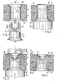
- FIGURE 1 shows an exploded side elevational partially sectional view of the rivet of this invention in combination with a fragmented sectional part to be joined.
- FIGURE 2 shows the rivet and part of FIGURE 1 with the rivet inserted and ready to be formed.
- FIGURE 3 shows the rivet being formed with forming dies.
- FIGURE 4 shows the rivet joined part.
- In
rivet 10 thehead 12 of the rivet is of the flush type and is at an angle of 100° to fit into a 100° countersink. Theshank 14 is of a constant diameter and is open ended opposite the head to form atubular end 16. The inside walls 18 of the tubular section are tapered outward at an angle of about 15° and terminate on a radius at 20. The rivets are used to join fiber reinforced laminates or fiber reinforced laminates to metals. It is imperative the rivet firmly hold the laminates without having the main part of the shank of the rivet expand during the forming process as the expanding shank sets up cracks in the laminate which causes structural failure. These rivets are made of an alloy of titanium and columbium to be compatible with laminates using graphite fibers as the reinforcement, but are not restricted to such use as the rivets are also used to join laminates of other materials. The alloy is preferably about 55% titanium and about 45% columbium. Straight walled tubular rivets and tubular rivets with inside walls tapered at 30° were completely unsatisfactory. Aluminum rivets may not be used to join laminates containing graphite as aluminum reacts chemically with the graphite. - In the figures an airplane elevator 22 is shown which is made up of a pair of
laminates titanium columbium rivets 14. The laminates are of graphite fibers in an epoxy resin, are drilled through withbore 28 and are countersunk to 100° at each side at 30 and 32. - When joining the laminates the rivet is selected of a diameter to provide a net to a clearance fit into the bore, the rivet inserted and forming
dies 34 and 36 located in a riveting machine not shown, are advanced to form abutton 38 ontubular end 16 with the button pressing against thecountersink 30. In forming the button the forming die uses contactingsurface 40 that is at an angle of about 130° instead of a conventional angle for a die, which would be at about the same angle as the countersink. Preferably the depth of the tubular section of the shank is greater than the depth of the countersink against which the button is formed. - These figures show a flush head rivet; however, it is not intended to limit the rivet to a flush head as other types of manufactured heads may be used as long as the opposite end of the rivet is tubular as shown.
Claims (5)
Priority Applications (3)
| Application Number | Priority Date | Filing Date | Title |
|---|---|---|---|
| EP80200575A EP0042018B1 (en) | 1980-06-16 | 1980-06-16 | Method of joining parts with semi-tubular rivets |
| AT80200575T ATE12676T1 (en) | 1980-06-16 | 1980-06-16 | METHOD OF CONNECTING PARTS WITH SEMI-BALLOW RIVETS. |
| DE8080200575T DE3070447D1 (en) | 1980-06-16 | 1980-06-16 | Method of joining parts with semi-tubular rivets |
Applications Claiming Priority (1)
| Application Number | Priority Date | Filing Date | Title |
|---|---|---|---|
| EP80200575A EP0042018B1 (en) | 1980-06-16 | 1980-06-16 | Method of joining parts with semi-tubular rivets |
Publications (2)
| Publication Number | Publication Date |
|---|---|
| EP0042018A1 true EP0042018A1 (en) | 1981-12-23 |
| EP0042018B1 EP0042018B1 (en) | 1985-04-10 |
Family
ID=8187011
Family Applications (1)
| Application Number | Title | Priority Date | Filing Date |
|---|---|---|---|
| EP80200575A Expired EP0042018B1 (en) | 1980-06-16 | 1980-06-16 | Method of joining parts with semi-tubular rivets |
Country Status (3)
| Country | Link |
|---|---|
| EP (1) | EP0042018B1 (en) |
| AT (1) | ATE12676T1 (en) |
| DE (1) | DE3070447D1 (en) |
Cited By (2)
| Publication number | Priority date | Publication date | Assignee | Title |
|---|---|---|---|---|
| WO1982001920A1 (en) * | 1980-12-04 | 1982-06-10 | Slutas Johan | A metal element adapted for securing another element in a hole therethrough and a method of making such a joint |
| EP3815810A1 (en) * | 2019-10-29 | 2021-05-05 | The Boeing Company | Automated rivet apparatus and method for automated installation of semi-tubular fastener rivets |
Families Citing this family (1)
| Publication number | Priority date | Publication date | Assignee | Title |
|---|---|---|---|---|
| FR2736116B1 (en) * | 1995-06-27 | 1997-08-08 | Valeo | SHOCK ABSORBER FLYWHEEL INTENDED TO BE INTERPOSED IN A MOTOR VEHICLE DRIVE UNIT COMPRISING IMPROVED SEALING MEANS |
Citations (8)
| Publication number | Priority date | Publication date | Assignee | Title |
|---|---|---|---|---|
| DE302110C (en) * | ||||
| US1503859A (en) * | 1920-11-01 | 1924-08-05 | Stimpson Edwin B Co | Tubular rivet and the like article |
| FR807626A (en) * | 1936-05-23 | 1937-01-16 | Flourishing rivet | |
| US2302501A (en) * | 1941-07-18 | 1942-11-17 | Gen Motors Corp | Riveted joint |
| DE1854640U (en) * | 1962-01-25 | 1962-07-05 | Xaver Sonntag | RIVET. |
| US3505923A (en) * | 1968-08-12 | 1970-04-14 | Hancock Ind Inc | Self-adjusting hinge rivet |
| DE1450977B2 (en) * | 1964-03-04 | 1971-01-21 | Fichtel & Sachs Ag, 8720 Schweinfurt | Rivet for fastening the friction lining of clutches, especially for motor vehicles, and tools for carrying out the riveting process |
| DE2446888A1 (en) * | 1974-06-19 | 1976-01-08 | Rosman Irwin E | RIVET |
-
1980
- 1980-06-16 DE DE8080200575T patent/DE3070447D1/en not_active Expired
- 1980-06-16 EP EP80200575A patent/EP0042018B1/en not_active Expired
- 1980-06-16 AT AT80200575T patent/ATE12676T1/en active
Patent Citations (8)
| Publication number | Priority date | Publication date | Assignee | Title |
|---|---|---|---|---|
| DE302110C (en) * | ||||
| US1503859A (en) * | 1920-11-01 | 1924-08-05 | Stimpson Edwin B Co | Tubular rivet and the like article |
| FR807626A (en) * | 1936-05-23 | 1937-01-16 | Flourishing rivet | |
| US2302501A (en) * | 1941-07-18 | 1942-11-17 | Gen Motors Corp | Riveted joint |
| DE1854640U (en) * | 1962-01-25 | 1962-07-05 | Xaver Sonntag | RIVET. |
| DE1450977B2 (en) * | 1964-03-04 | 1971-01-21 | Fichtel & Sachs Ag, 8720 Schweinfurt | Rivet for fastening the friction lining of clutches, especially for motor vehicles, and tools for carrying out the riveting process |
| US3505923A (en) * | 1968-08-12 | 1970-04-14 | Hancock Ind Inc | Self-adjusting hinge rivet |
| DE2446888A1 (en) * | 1974-06-19 | 1976-01-08 | Rosman Irwin E | RIVET |
Cited By (4)
| Publication number | Priority date | Publication date | Assignee | Title |
|---|---|---|---|---|
| WO1982001920A1 (en) * | 1980-12-04 | 1982-06-10 | Slutas Johan | A metal element adapted for securing another element in a hole therethrough and a method of making such a joint |
| EP3815810A1 (en) * | 2019-10-29 | 2021-05-05 | The Boeing Company | Automated rivet apparatus and method for automated installation of semi-tubular fastener rivets |
| US11185912B2 (en) | 2019-10-29 | 2021-11-30 | The Boeing Company | Automated rivet apparatus for automated installation of semi-tubular fastener rivets |
| US11453044B2 (en) | 2019-10-29 | 2022-09-27 | The Boeing Company | Method for automated installation of semi-tubular fastener rivets |
Also Published As
| Publication number | Publication date |
|---|---|
| ATE12676T1 (en) | 1985-04-15 |
| DE3070447D1 (en) | 1985-05-15 |
| EP0042018B1 (en) | 1985-04-10 |
Similar Documents
| Publication | Publication Date | Title |
|---|---|---|
| US4221041A (en) | Semi-tubular rivets and method of using | |
| US7937821B2 (en) | Blind rivet method | |
| JP4602984B2 (en) | Self-piercing anchor | |
| US5375953A (en) | Blind rivet | |
| EP0780581B1 (en) | Plastic composite fastener | |
| US4863325A (en) | Two piece blind fastener with lock spindle construction | |
| US20110027042A1 (en) | Blind rivet | |
| CA2048689C (en) | Self-drilling fastening | |
| US20080107499A1 (en) | Blind fastener and method of installation thereof | |
| EP0760722A1 (en) | Improved means of fastening sheets by rivetting | |
| AU2007213931B2 (en) | Blind rivet and associated method | |
| JPH0285510A (en) | Self-closing blind clamping tool | |
| US20040194284A1 (en) | Adhesive encapsulated blind rivet system | |
| EP1380760B1 (en) | Self piercing rivet | |
| EP0237957A2 (en) | Fastener for securing panels of composite materials | |
| US2492605A (en) | Hydraulically expansible hollow rivet | |
| EP0042018A1 (en) | Method of joining parts with semi-tubular rivets | |
| USRE38664E1 (en) | Method for creating a hole for a permanent fastener that replaces a tacking fastener | |
| US2787932A (en) | Blind rivet having tapered expander pin therein | |
| EP0053634A1 (en) | Fastener assembly | |
| US3009383A (en) | Hollow rivet for easily deformable structures | |
| US4749323A (en) | Hole expanding rivet with a shaded tail | |
| EP0181881A1 (en) | Rivets | |
| CA1275190C (en) | Sheathed composite blind rivet | |
| EP0329869B1 (en) | A rivet and a roofing structure utilizing same |
Legal Events
| Date | Code | Title | Description |
|---|---|---|---|
| PUAI | Public reference made under article 153(3) epc to a published international application that has entered the european phase |
Free format text: ORIGINAL CODE: 0009012 |
|
| AK | Designated contracting states |
Designated state(s): AT BE DE FR GB IT NL SE |
|
| 17P | Request for examination filed |
Effective date: 19811203 |
|
| ITF | It: translation for a ep patent filed |
Owner name: STUDIO INGG. FISCHETTI & WEBER |
|
| GRAA | (expected) grant |
Free format text: ORIGINAL CODE: 0009210 |
|
| AK | Designated contracting states |
Designated state(s): AT BE DE FR GB IT NL SE |
|
| REF | Corresponds to: |
Ref document number: 12676 Country of ref document: AT Date of ref document: 19850415 Kind code of ref document: T |
|
| PG25 | Lapsed in a contracting state [announced via postgrant information from national office to epo] |
Ref country code: SE Effective date: 19850430 |
|
| REF | Corresponds to: |
Ref document number: 3070447 Country of ref document: DE Date of ref document: 19850515 |
|
| ET | Fr: translation filed | ||
| PLBI | Opposition filed |
Free format text: ORIGINAL CODE: 0009260 |
|
| 26 | Opposition filed |
Opponent name: MESSERSCHMIDT - BOELKOW - BLOHM GMBH, OTTOBRUNN Effective date: 19860108 |
|
| NLR1 | Nl: opposition has been filed with the epo |
Opponent name: MESSERSCHMIDT-BOELKOW-BLOHM GMBH |
|
| PLBN | Opposition rejected |
Free format text: ORIGINAL CODE: 0009273 |
|
| STAA | Information on the status of an ep patent application or granted ep patent |
Free format text: STATUS: OPPOSITION REJECTED |
|
| 27O | Opposition rejected |
Effective date: 19891009 |
|
| NLR2 | Nl: decision of opposition | ||
| ITTA | It: last paid annual fee | ||
| PGFP | Annual fee paid to national office [announced via postgrant information from national office to epo] |
Ref country code: GB Payment date: 19940613 Year of fee payment: 15 |
|
| PGFP | Annual fee paid to national office [announced via postgrant information from national office to epo] |
Ref country code: AT Payment date: 19940628 Year of fee payment: 15 |
|
| PGFP | Annual fee paid to national office [announced via postgrant information from national office to epo] |
Ref country code: NL Payment date: 19940630 Year of fee payment: 15 Ref country code: FR Payment date: 19940630 Year of fee payment: 15 |
|
| PGFP | Annual fee paid to national office [announced via postgrant information from national office to epo] |
Ref country code: BE Payment date: 19940725 Year of fee payment: 15 |
|
| PGFP | Annual fee paid to national office [announced via postgrant information from national office to epo] |
Ref country code: DE Payment date: 19940729 Year of fee payment: 15 |
|
| PG25 | Lapsed in a contracting state [announced via postgrant information from national office to epo] |
Ref country code: GB Effective date: 19950616 Ref country code: AT Effective date: 19950616 |
|
| PG25 | Lapsed in a contracting state [announced via postgrant information from national office to epo] |
Ref country code: BE Effective date: 19950630 |
|
| BERE | Be: lapsed |
Owner name: THE BOEING CY Effective date: 19950630 |
|
| PG25 | Lapsed in a contracting state [announced via postgrant information from national office to epo] |
Ref country code: NL Effective date: 19960101 |
|
| GBPC | Gb: european patent ceased through non-payment of renewal fee |
Effective date: 19950616 |
|
| PG25 | Lapsed in a contracting state [announced via postgrant information from national office to epo] |
Ref country code: FR Effective date: 19960229 |
|
| NLV4 | Nl: lapsed or anulled due to non-payment of the annual fee |
Effective date: 19960101 |
|
| PG25 | Lapsed in a contracting state [announced via postgrant information from national office to epo] |
Ref country code: DE Effective date: 19960301 |
|
| REG | Reference to a national code |
Ref country code: FR Ref legal event code: ST |
|
| APAH | Appeal reference modified |
Free format text: ORIGINAL CODE: EPIDOSCREFNO |