EP0041799B1 - Stereophonic pick-up cartridges - Google Patents
Stereophonic pick-up cartridges Download PDFInfo
- Publication number
- EP0041799B1 EP0041799B1 EP81302362A EP81302362A EP0041799B1 EP 0041799 B1 EP0041799 B1 EP 0041799B1 EP 81302362 A EP81302362 A EP 81302362A EP 81302362 A EP81302362 A EP 81302362A EP 0041799 B1 EP0041799 B1 EP 0041799B1
- Authority
- EP
- European Patent Office
- Prior art keywords
- damper
- grooves
- cartridge
- armature
- cantilever
- Prior art date
- Legal status (The legal status is an assumption and is not a legal conclusion. Google has not performed a legal analysis and makes no representation as to the accuracy of the status listed.)
- Expired
Links
- 241001422033 Thestylus Species 0.000 description 2
- 230000005540 biological transmission Effects 0.000 description 2
- 230000000694 effects Effects 0.000 description 2
- 230000002463 transducing effect Effects 0.000 description 2
- 229920005549 butyl rubber Polymers 0.000 description 1
- 238000010276 construction Methods 0.000 description 1
- 229920001971 elastomer Polymers 0.000 description 1
- 230000008030 elimination Effects 0.000 description 1
- 238000003379 elimination reaction Methods 0.000 description 1
- 239000000463 material Substances 0.000 description 1
- 238000000926 separation method Methods 0.000 description 1
- 239000000126 substance Substances 0.000 description 1
- 239000000725 suspension Substances 0.000 description 1
Images

Classifications
-
- G—PHYSICS
- G11—INFORMATION STORAGE
- G11B—INFORMATION STORAGE BASED ON RELATIVE MOVEMENT BETWEEN RECORD CARRIER AND TRANSDUCER
- G11B3/00—Recording by mechanical cutting, deforming or pressing, e.g. of grooves or pits; Reproducing by mechanical sensing; Record carriers therefor
- G11B3/44—Styli, e.g. sapphire, diamond
- G11B3/46—Constructions or forms ; Dispositions or mountings, e.g. attachment of point to shank
-
- H—ELECTRICITY
- H04—ELECTRIC COMMUNICATION TECHNIQUE
- H04R—LOUDSPEAKERS, MICROPHONES, GRAMOPHONE PICK-UPS OR LIKE ACOUSTIC ELECTROMECHANICAL TRANSDUCERS; DEAF-AID SETS; PUBLIC ADDRESS SYSTEMS
- H04R1/00—Details of transducers, loudspeakers or microphones
- H04R1/16—Mounting or connecting stylus to transducer with or without damping means
Definitions
- This invention relates to stereophonic pick-up cartridges, and is particularly concerned with the supporting mechanism for the armature of a pick-up cartridge.
- a hollow cantilever 1 has a stylus 2 on one end thereof and carries an armature 3 at the other end.
- the armature 3 would be a magnet if the cartridge is a moving magnet type or it would comprise a coil bobbin including coils if the cartridge is of a moving coil type.
- the armature 3 is generally disc-shaped and is attached to the rear end of the cantilever 1, with the cantilever 1 extending through a central opening formed in the armature 3.
- a piano wire 4 extends through the opening in the armature 3 and the opening through the cantilever 1 and has one end attached to a suspension sleeve 5 which is connected to an axial bore of a metallic holder 6.
- the other end of the wire 4 is connected to the cantilever 1 adjacent to the stylus 2.
- a cylindrical damper 7 Between the end plane of the holder 6 and the armature 3 is mounted a cylindrical damper 7 so as to allow the cantilever 1 to move in response to tracking of the stylus 2 in the grooves on a record.
- the damper 7 has a central aperture for the wire 4 and the sleeve 5 and may be made from a flexible substance such as rubber.
- the armature 3 is firmly pressed against the damper 7 by the tension of the wire 4.
- Figure 2 is an enlarged perspective view of parts of the cartridge of Figure 1.
- the armature 3 in the directions indicated by the arrows A-A' which is identified as “vibration in the right channel direction” and which results from transducing the right channel electrical signals from one wall of a groove of a record, and the direction indicated by arrows B-B' which is identified as “vibration in the left channel direction” and which results from transducing the left channel eiectricat signals from the other wall of the groove on the record.
- Figure 3 is a plot of the output frequency response of the left channel signals L and the output frequency response of cross-talk of the left channel electrical signals with the right channel indicated as L-+R.
- a stereophonic pick-up cartridge comprising a cantilever having a stylus on a free end thereof and an armature at the rear end thereof, a fixed support, and a damper having a first plane surface abutting said fixed support and a second plane surface abutting said armature, grooves being formed in said second plane surface of said damper, characterised in that said grooves are open and extend radially from a central axis of said damper through the periphery of said damper, a first pair of said grooves have longitudinal directions which in use of the cartridge are parallel to the surface of a record disc and a second pair of said grooves have longitudinal directions which in use of the cartridge are normal to the surface of said record disc.
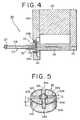
- FIG. 4 illustrates an embodiment of stereophonic moving coil type cartridge 20 according to the invention.
- the invention is equally applicable to a permanent magnet type cartridge.
- the cartridge 20 includes a magnetic circuit 21 and a vibration system 22.
- the magnetic circuit 21 includes a pair of yokes 23 and 24 at one end, and a pole piece 26 fixed between the other ends of the yokes 23 and 24.
- the vibration system 22 includes a stylus 27 mounted on the end of a cantilever 28 and an armature 29 is mounted on the other end of the cantilever 28.
- the rear end of the armature 29 is generally disc-shaped as shown and rests on a cylindrical damper 30 made of a flexible material such as butyl rubber and which has one major surface abutting the pole piece 26 and the other major surface abutting the armature 29.
- a piano wire 31 is secured to the pole piece 26 by a screw or other means (not shown) and the other end is attached to the cantilever 28.
- the armature 29 is firmly pressed against the damper 30 due to the tension in the wire 31.
- the armature 29 comprises a coil bobbin 29a and coils 29b.
- the shape of the coils 29b and the bobbin 29a are visible in Figure 4.
- FIG. 4 For more details relating generally to stereophonic pick-up cartridges reference may be made to our US patent specification 4 090 039.
- FIG. 5 is an enlarged detailed perspective view of the damper 30.
- the damper 30 has crossed rectangular cross-section grooves 301, 302, 303 and 304 which extend from a central aperture 305 to the outer periphery 306 formed in the surface which abuts the armature 29.
- the grooves 301 to 304 divide the surface of the damper 30 into four portions 307, 308, 309 and 310. As shown, the grooves 301 to 304 are open and extend in from the engaging surface of the damper 30 with the armature 29 and the grooves 301 and 302 are normal to the grooves 303 and 304.
- one pair of the grooves 301 to 304 have longitudinal directions which in use of the cartridge are normal to the surface of the record disc and therefore the other pair of the grooves 301 to 304 have longitudinal directions which in use of the cartridge are parallel to the surface of the record disc.
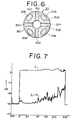
- the coils 29b are wound on the coil bobbin 29a and are located above each of the abutting portions 307 to 310 as indicated in Figure 6.
- the widths of the grooves 301 to 304 can be 0.3 mm if the diameter of the damper 30 is 2.5 mm, and the depths 1 2 of the grooves 301 to 304 can be equal to one-half of the thickness 1 3 of the damper 30 as illustrated in Figure 5.
- the grooves 301 to 304 substantially eliminate transmission of deformation between the left and right channel directions in the damper 30, while allowing full movement of the armature 29 relative to the damper 30. Due to the substantial elimination of this transmission of deformation, cross-talk between the left and right channels will also be substantially reduced.
- Figure 7 comprises a plot of the output frequency response of the channel signals L as well as the output frequency of the cross-talk response comprising the left channel electrical signals relative to the right channel electrical signals L-R. It is to be noted that as can be seen by comparing Figure 7 with Figure 3 that the cross-talk response in Figure 7 is much less than that illustrated in Figure 3. Thus, much improved frequency response is achieved particularly at higher frequencies.
Description
- This invention relates to stereophonic pick-up cartridges, and is particularly concerned with the supporting mechanism for the armature of a pick-up cartridge.
- Generally, the supporting mechanism for the armature of a pick-up cartridge of the moving magnet or moving coil type is as illustrated in Figures 1 and 2 of the accompanying drawings.
- As shown in Figure 1, a hollow cantilever 1 has a
stylus 2 on one end thereof and carries anarmature 3 at the other end. Thearmature 3 would be a magnet if the cartridge is a moving magnet type or it would comprise a coil bobbin including coils if the cartridge is of a moving coil type. Thearmature 3 is generally disc-shaped and is attached to the rear end of the cantilever 1, with the cantilever 1 extending through a central opening formed in thearmature 3. Apiano wire 4 extends through the opening in thearmature 3 and the opening through the cantilever 1 and has one end attached to asuspension sleeve 5 which is connected to an axial bore of ametallic holder 6. The other end of thewire 4 is connected to the cantilever 1 adjacent to thestylus 2. Between the end plane of theholder 6 and thearmature 3 is mounted a cylindrical damper 7 so as to allow the cantilever 1 to move in response to tracking of thestylus 2 in the grooves on a record. The damper 7 has a central aperture for thewire 4 and thesleeve 5 and may be made from a flexible substance such as rubber. Thearmature 3 is firmly pressed against the damper 7 by the tension of thewire 4. - Figure 2 is an enlarged perspective view of parts of the cartridge of Figure 1. With the construction illustrated in Figure 1, it is difficult to eliminate vibration-induced mutual interference of the
armature 3 in the directions indicated by the arrows A-A' which is identified as "vibration in the right channel direction" and which results from transducing the right channel electrical signals from one wall of a groove of a record, and the direction indicated by arrows B-B' which is identified as "vibration in the left channel direction" and which results from transducing the left channel eiectricat signals from the other wall of the groove on the record. This is because a movement of the cantilever 1 when vibrating in the direction A-A', for example, applies a force which resiliently deforms the damper 7, and, as this deformation is transmitted through the damper 7, the effect is to move a central axis G of thearmature 3. This affects movement of the cantilever 1 in the left direction B-B' causing cross-talk between the two channels. - For this reason, separation between the left and right channel electrical signals from the stereophonic pick-up cartridge is degradated.
- Figure 3 is a plot of the output frequency response of the left channel signals L and the output frequency response of cross-talk of the left channel electrical signals with the right channel indicated as L-+R.
- According to the present invention there is provided a stereophonic pick-up cartridge comprising a cantilever having a stylus on a free end thereof and an armature at the rear end thereof, a fixed support, and a damper having a first plane surface abutting said fixed support and a second plane surface abutting said armature, grooves being formed in said second plane surface of said damper, characterised in that said grooves are open and extend radially from a central axis of said damper through the periphery of said damper, a first pair of said grooves have longitudinal directions which in use of the cartridge are parallel to the surface of a record disc and a second pair of said grooves have longitudinal directions which in use of the cartridge are normal to the surface of said record disc.
- West German Offenlegungsschrift 29 01 714 and US
specification 3 926 441 referred to in the European search report disclose dampers with grooves, but these grooves are different in configuration and effect from those in embodiments of the present invention. - The invention will now be described by way of example with reference to the accompanying drawings, in which:
- Figure 1 is a partially sectional view of part of a previously proposed pick-up cartridge;
- Figure 2 is a perspective view of part of the cartridge of Figure 1;
- Figure 3 is a plot of frequency response illustrating cross-talk in the cartridge of Figures 1 and 2;
- Figure 4 is a cross-sectional view of an embodiment of moving coil type stereophonic pick-up cartridge according to the invention;
- Figure 5 is a perspective view of a cylindrical damper of the cartridge of Figure 4;
- Figure 6 is an elevational view of the damper of Figure 5 and indicates the location of the coils of the cartridge; and
- Figure 7 is a plot of the frequency response and cross-talk of the embodiment.
- Figure 4 illustrates an embodiment of stereophonic moving
coil type cartridge 20 according to the invention. The invention is equally applicable to a permanent magnet type cartridge. Thecartridge 20 includes amagnetic circuit 21 and avibration system 22. Themagnetic circuit 21 includes a pair ofyokes pole piece 26 fixed between the other ends of theyokes vibration system 22 includes astylus 27 mounted on the end of acantilever 28 and anarmature 29 is mounted on the other end of thecantilever 28. The rear end of thearmature 29 is generally disc-shaped as shown and rests on acylindrical damper 30 made of a flexible material such as butyl rubber and which has one major surface abutting thepole piece 26 and the other major surface abutting thearmature 29. Apiano wire 31 is secured to thepole piece 26 by a screw or other means (not shown) and the other end is attached to thecantilever 28. Thearmature 29 is firmly pressed against thedamper 30 due to the tension in thewire 31. - The
armature 29 comprises acoil bobbin 29a andcoils 29b. The shape of thecoils 29b and thebobbin 29a are visible in Figure 4. For more details relating generally to stereophonic pick-up cartridges reference may be made to our USpatent specification 4 090 039. - Figure 5 is an enlarged detailed perspective view of the
damper 30. Thedamper 30 has crossedrectangular cross-section grooves central aperture 305 to theouter periphery 306 formed in the surface which abuts thearmature 29. Thegrooves 301 to 304 divide the surface of thedamper 30 into fourportions grooves 301 to 304 are open and extend in from the engaging surface of thedamper 30 with thearmature 29 and thegrooves grooves grooves 301 to 304 have longitudinal directions which in use of the cartridge are normal to the surface of the record disc and therefore the other pair of thegrooves 301 to 304 have longitudinal directions which in use of the cartridge are parallel to the surface of the record disc. - The
coils 29b are wound on thecoil bobbin 29a and are located above each of theabutting portions 307 to 310 as indicated in Figure 6. The widths of thegrooves 301 to 304 can be 0.3 mm if the diameter of thedamper 30 is 2.5 mm, and the depths 12 of thegrooves 301 to 304 can be equal to one-half of the thickness 13 of thedamper 30 as illustrated in Figure 5. Thegrooves 301 to 304 substantially eliminate transmission of deformation between the left and right channel directions in thedamper 30, while allowing full movement of thearmature 29 relative to thedamper 30. Due to the substantial elimination of this transmission of deformation, cross-talk between the left and right channels will also be substantially reduced. - Figure 7 comprises a plot of the output frequency response of the channel signals L as well as the output frequency of the cross-talk response comprising the left channel electrical signals relative to the right channel electrical signals L-R. It is to be noted that as can be seen by comparing Figure 7 with Figure 3 that the cross-talk response in Figure 7 is much less than that illustrated in Figure 3. Thus, much improved frequency response is achieved particularly at higher frequencies.
Claims (6)
Applications Claiming Priority (2)
| Application Number | Priority Date | Filing Date | Title |
|---|---|---|---|
| JP75950/80 | 1980-06-05 | ||
| JP7595080A JPS573203A (en) | 1980-06-05 | 1980-06-05 | Stereo cartridge |
Publications (2)
| Publication Number | Publication Date |
|---|---|
| EP0041799A1 EP0041799A1 (en) | 1981-12-16 |
| EP0041799B1 true EP0041799B1 (en) | 1984-03-14 |
Family
ID=13590999
Family Applications (1)
| Application Number | Title | Priority Date | Filing Date |
|---|---|---|---|
| EP81302362A Expired EP0041799B1 (en) | 1980-06-05 | 1981-05-28 | Stereophonic pick-up cartridges |
Country Status (5)
| Country | Link |
|---|---|
| US (1) | US4410975A (en) |
| EP (1) | EP0041799B1 (en) |
| JP (1) | JPS573203A (en) |
| DE (1) | DE3162617D1 (en) |
| DK (1) | DK151675C (en) |
Family Cites Families (5)
| Publication number | Priority date | Publication date | Assignee | Title |
|---|---|---|---|---|
| US2578809A (en) * | 1948-01-07 | 1951-12-18 | Admiral Corp | Phonograph pickup |
| CH438775A (en) * | 1965-12-31 | 1967-06-30 | Dual Gebrueder Steidinger | Pickups |
| JPS5554809Y2 (en) * | 1973-05-15 | 1980-12-18 | ||
| JPS5122362B2 (en) * | 1973-11-27 | 1976-07-09 | ||
| US4281225A (en) * | 1978-01-17 | 1981-07-28 | Nippon Gakki Seizo Kabushiki Kaisha | Pickup cartridge for reproducing signals recorded on a 45-45 stereophonic record disk |
-
1980
- 1980-06-05 JP JP7595080A patent/JPS573203A/en active Granted
-
1981
- 1981-05-28 EP EP81302362A patent/EP0041799B1/en not_active Expired
- 1981-05-28 DE DE8181302362T patent/DE3162617D1/en not_active Expired
- 1981-06-02 US US06/269,556 patent/US4410975A/en not_active Expired - Fee Related
- 1981-06-03 DK DK244281A patent/DK151675C/en active
Also Published As
| Publication number | Publication date |
|---|---|
| JPS639281B2 (en) | 1988-02-26 |
| JPS573203A (en) | 1982-01-08 |
| EP0041799A1 (en) | 1981-12-16 |
| DE3162617D1 (en) | 1984-04-19 |
| DK151675C (en) | 1988-05-24 |
| US4410975A (en) | 1983-10-18 |
| DK244281A (en) | 1981-12-06 |
| DK151675B (en) | 1987-12-21 |
Similar Documents
| Publication | Publication Date | Title |
|---|---|---|
| GB2162718A (en) | Electro-vibration transducer | |
| JPH0658417U (en) | Optical device | |
| US4138122A (en) | Pickup | |
| EP0041799B1 (en) | Stereophonic pick-up cartridges | |
| EP0002955B1 (en) | A moving-coil pickup | |
| US3108161A (en) | Stereophonic phonograph pickup | |
| JPH0349137B2 (en) | ||
| US4075418A (en) | Stereophonic pickup cartridge | |
| US4103117A (en) | Pick-up cartridge | |
| CA1038300A (en) | Phonograph pickup cartridge | |
| US3908096A (en) | Electromagnetic pickup cartridge with tension wire and induction magnet alined axially with armature | |
| US3983335A (en) | Stylus assembly and transducer using same | |
| EP0784415B1 (en) | Electroacoustic transducer | |
| US4263483A (en) | Moving coil pick-up assembly for use in a record player | |
| US4488284A (en) | Moving-coil type pickup cartridge | |
| US4327433A (en) | Magnetic phono cartridge | |
| GB2055272A (en) | Moving coil type stereophonic pickup cartridge | |
| US4455639A (en) | Moving coil type pickup cartridge | |
| EP0031122B1 (en) | Electromagnetic pickup cartridge | |
| US4281225A (en) | Pickup cartridge for reproducing signals recorded on a 45-45 stereophonic record disk | |
| US4238646A (en) | Pickup cartridge for reproducing signals recorded on a 45--45 stereophonic record disk | |
| EP0004158B1 (en) | Pick-up | |
| US4249747A (en) | Phonograph pick-up cartridge | |
| US5590007A (en) | Magnetic head driving apparatus having a magnetic head which is immune to the influence of a magnetic circuit | |
| US4037060A (en) | Stereophonic pickup cartridge |
Legal Events
| Date | Code | Title | Description |
|---|---|---|---|
| PUAI | Public reference made under article 153(3) epc to a published international application that has entered the european phase |
Free format text: ORIGINAL CODE: 0009012 |
|
| AK | Designated contracting states |
Designated state(s): DE FR GB NL SE |
|
| 17P | Request for examination filed |
Effective date: 19811026 |
|
| GRAA | (expected) grant |
Free format text: ORIGINAL CODE: 0009210 |
|
| AK | Designated contracting states |
Designated state(s): DE FR GB NL SE |
|
| REF | Corresponds to: |
Ref document number: 3162617 Country of ref document: DE Date of ref document: 19840419 |
|
| ET | Fr: translation filed | ||
| PLBE | No opposition filed within time limit |
Free format text: ORIGINAL CODE: 0009261 |
|
| PLAA | Information modified related to event that no opposition was filed |
Free format text: ORIGINAL CODE: 0009299DELT |
|
| STAA | Information on the status of an ep patent application or granted ep patent |
Free format text: STATUS: NO OPPOSITION FILED WITHIN TIME LIMIT |
|
| 26N | No opposition filed | ||
| PGFP | Annual fee paid to national office [announced via postgrant information from national office to epo] |
Ref country code: SE Payment date: 19920518 Year of fee payment: 12 |
|
| PGFP | Annual fee paid to national office [announced via postgrant information from national office to epo] |
Ref country code: GB Payment date: 19920527 Year of fee payment: 12 |
|
| PGFP | Annual fee paid to national office [announced via postgrant information from national office to epo] |
Ref country code: NL Payment date: 19920531 Year of fee payment: 12 |
|
| PGFP | Annual fee paid to national office [announced via postgrant information from national office to epo] |
Ref country code: DE Payment date: 19920729 Year of fee payment: 12 |
|
| PGFP | Annual fee paid to national office [announced via postgrant information from national office to epo] |
Ref country code: FR Payment date: 19930526 Year of fee payment: 13 |
|
| PG25 | Lapsed in a contracting state [announced via postgrant information from national office to epo] |
Ref country code: GB Effective date: 19930528 |
|
| PG25 | Lapsed in a contracting state [announced via postgrant information from national office to epo] |
Ref country code: SE Effective date: 19930529 |
|
| PG25 | Lapsed in a contracting state [announced via postgrant information from national office to epo] |
Ref country code: NL Effective date: 19931201 |
|
| NLV4 | Nl: lapsed or anulled due to non-payment of the annual fee | ||
| GBPC | Gb: european patent ceased through non-payment of renewal fee |
Effective date: 19930528 |
|
| PG25 | Lapsed in a contracting state [announced via postgrant information from national office to epo] |
Ref country code: DE Effective date: 19940201 |
|
| EUG | Se: european patent has lapsed |
Ref document number: 81302362.9 Effective date: 19931210 |
|
| PG25 | Lapsed in a contracting state [announced via postgrant information from national office to epo] |
Ref country code: FR Effective date: 19950131 |
|
| REG | Reference to a national code |
Ref country code: FR Ref legal event code: ST |