EP0041599A2 - Force sensor, in particular for ballistic pressure measurements - Google Patents
Force sensor, in particular for ballistic pressure measurements Download PDFInfo
- Publication number
- EP0041599A2 EP0041599A2 EP81102275A EP81102275A EP0041599A2 EP 0041599 A2 EP0041599 A2 EP 0041599A2 EP 81102275 A EP81102275 A EP 81102275A EP 81102275 A EP81102275 A EP 81102275A EP 0041599 A2 EP0041599 A2 EP 0041599A2
- Authority
- EP
- European Patent Office
- Prior art keywords
- force
- force transmission
- pressure
- transmission element
- outer sleeve
- Prior art date
- Legal status (The legal status is an assumption and is not a legal conclusion. Google has not performed a legal analysis and makes no representation as to the accuracy of the status listed.)
- Granted
Links
- 238000009530 blood pressure measurement Methods 0.000 title claims description 8
- 230000005540 biological transmission Effects 0.000 claims abstract description 116
- 230000035945 sensitivity Effects 0.000 claims description 17
- 238000000034 method Methods 0.000 claims description 13
- 238000012937 correction Methods 0.000 claims description 11
- 238000001514 detection method Methods 0.000 claims description 9
- 230000004044 response Effects 0.000 claims description 8
- 238000004519 manufacturing process Methods 0.000 claims description 4
- 238000004891 communication Methods 0.000 claims 1
- 239000010453 quartz Substances 0.000 abstract description 27
- VYPSYNLAJGMNEJ-UHFFFAOYSA-N silicon dioxide Inorganic materials O=[Si]=O VYPSYNLAJGMNEJ-UHFFFAOYSA-N 0.000 abstract description 27
- 238000011088 calibration curve Methods 0.000 abstract description 17
- 238000002485 combustion reaction Methods 0.000 abstract description 7
- 239000000843 powder Substances 0.000 abstract description 5
- 238000009434 installation Methods 0.000 abstract description 3
- 235000012239 silicon dioxide Nutrition 0.000 description 47
- 238000005259 measurement Methods 0.000 description 20
- 101100328887 Caenorhabditis elegans col-34 gene Proteins 0.000 description 14
- 239000007789 gas Substances 0.000 description 13
- 239000013078 crystal Substances 0.000 description 11
- 230000000694 effects Effects 0.000 description 10
- 239000012528 membrane Substances 0.000 description 10
- 238000006073 displacement reaction Methods 0.000 description 9
- 238000013461 design Methods 0.000 description 7
- 230000009467 reduction Effects 0.000 description 7
- 230000006835 compression Effects 0.000 description 6
- 238000007906 compression Methods 0.000 description 6
- 230000008901 benefit Effects 0.000 description 5
- 230000003068 static effect Effects 0.000 description 5
- RYGMFSIKBFXOCR-UHFFFAOYSA-N Copper Chemical compound [Cu] RYGMFSIKBFXOCR-UHFFFAOYSA-N 0.000 description 4
- 230000009471 action Effects 0.000 description 4
- 230000015572 biosynthetic process Effects 0.000 description 4
- 239000010949 copper Substances 0.000 description 4
- 229910052802 copper Inorganic materials 0.000 description 4
- 238000009826 distribution Methods 0.000 description 4
- 238000012360 testing method Methods 0.000 description 4
- 238000010276 construction Methods 0.000 description 3
- 238000005516 engineering process Methods 0.000 description 3
- 239000007788 liquid Substances 0.000 description 3
- 239000000463 material Substances 0.000 description 3
- 238000012546 transfer Methods 0.000 description 3
- 230000006978 adaptation Effects 0.000 description 2
- 239000000567 combustion gas Substances 0.000 description 2
- 238000005553 drilling Methods 0.000 description 2
- 238000004880 explosion Methods 0.000 description 2
- 230000002093 peripheral effect Effects 0.000 description 2
- 230000007704 transition Effects 0.000 description 2
- 229910001369 Brass Inorganic materials 0.000 description 1
- 229910000831 Steel Inorganic materials 0.000 description 1
- 238000010521 absorption reaction Methods 0.000 description 1
- 230000001133 acceleration Effects 0.000 description 1
- 230000004323 axial length Effects 0.000 description 1
- 239000010951 brass Substances 0.000 description 1
- 238000004364 calculation method Methods 0.000 description 1
- 230000002844 continuous effect Effects 0.000 description 1
- 238000011161 development Methods 0.000 description 1
- 230000018109 developmental process Effects 0.000 description 1
- 238000011156 evaluation Methods 0.000 description 1
- 239000004519 grease Substances 0.000 description 1
- 238000000265 homogenisation Methods 0.000 description 1
- 239000002655 kraft paper Substances 0.000 description 1
- 238000012423 maintenance Methods 0.000 description 1
- 238000005192 partition Methods 0.000 description 1
- 238000002360 preparation method Methods 0.000 description 1
- 238000007639 printing Methods 0.000 description 1
- 230000008569 process Effects 0.000 description 1
- 239000004065 semiconductor Substances 0.000 description 1
- 238000004904 shortening Methods 0.000 description 1
- 239000007787 solid Substances 0.000 description 1
- 239000010959 steel Substances 0.000 description 1
- 238000003860 storage Methods 0.000 description 1
- 239000000126 substance Substances 0.000 description 1
- 230000001629 suppression Effects 0.000 description 1
- 230000009897 systematic effect Effects 0.000 description 1
- 230000002277 temperature effect Effects 0.000 description 1
- 238000011144 upstream manufacturing Methods 0.000 description 1
Images


Classifications
-
- G—PHYSICS
- G01—MEASURING; TESTING
- G01L—MEASURING FORCE, STRESS, TORQUE, WORK, MECHANICAL POWER, MECHANICAL EFFICIENCY, OR FLUID PRESSURE
- G01L5/00—Apparatus for, or methods of, measuring force, work, mechanical power, or torque, specially adapted for specific purposes
- G01L5/14—Apparatus for, or methods of, measuring force, work, mechanical power, or torque, specially adapted for specific purposes for measuring the force of explosions; for measuring the energy of projectiles
-
- F—MECHANICAL ENGINEERING; LIGHTING; HEATING; WEAPONS; BLASTING
- F42—AMMUNITION; BLASTING
- F42B—EXPLOSIVE CHARGES, e.g. FOR BLASTING, FIREWORKS, AMMUNITION
- F42B35/00—Testing or checking of ammunition
-
- G—PHYSICS
- G01—MEASURING; TESTING
- G01L—MEASURING FORCE, STRESS, TORQUE, WORK, MECHANICAL POWER, MECHANICAL EFFICIENCY, OR FLUID PRESSURE
- G01L1/00—Measuring force or stress, in general
- G01L1/16—Measuring force or stress, in general using properties of piezoelectric devices
-
- G—PHYSICS
- G01—MEASURING; TESTING
- G01L—MEASURING FORCE, STRESS, TORQUE, WORK, MECHANICAL POWER, MECHANICAL EFFICIENCY, OR FLUID PRESSURE
- G01L23/00—Devices or apparatus for measuring or indicating or recording rapid changes, such as oscillations, in the pressure of steam, gas, or liquid; Indicators for determining work or energy of steam, internal-combustion, or other fluid-pressure engines from the condition of the working fluid
- G01L23/08—Devices or apparatus for measuring or indicating or recording rapid changes, such as oscillations, in the pressure of steam, gas, or liquid; Indicators for determining work or energy of steam, internal-combustion, or other fluid-pressure engines from the condition of the working fluid operated electrically
- G01L23/10—Devices or apparatus for measuring or indicating or recording rapid changes, such as oscillations, in the pressure of steam, gas, or liquid; Indicators for determining work or energy of steam, internal-combustion, or other fluid-pressure engines from the condition of the working fluid operated electrically by pressure-sensitive members of the piezoelectric type
Definitions
- the invention relates to a force transducer, in particular for ballistic pressure measurements, with a force transmission element subjected to the pressure to be measured on its one end face, a detection element held under tension between the force transmission element and a transducer base part, and an outer sleeve surrounding the force transmission element and exposed to the pressure to be measured on the end face, and a process for its manufacture.
- a known procedure provides for the use of so-called copper crushers (copper upsetting cylinders).
- the cartridge case is drilled and the combustion gases are passed into a cylinder with a piston.
- the piston presses on a cylindrical piece of copper, which is more or less compressed depending on the pressure of the combustion gas.
- This method is used for comparison tests; it does not provide any information about the prevailing peak pressures, since the compression depends not only on the peak pressure, but also on the exposure time to the pressure.
- the required connection channel to the force transducer means an additional volume, and the pressure build-up is less high because of the larger volume behind the cartridge case.
- the measured peak pressures therefore do not correspond to the real pressures in the cartridge case.
- Another method involves measuring the pressure directly in the receiving bore of the cartridge chamber into which the cartridge case is inserted.
- the drilling of the cartridge case can be avoided.
- this method has the disadvantage that no measurement signal is received until the projectile leaves the mounting hole.
- the pressure build-up inside the cartridge case during the first phase of the combustion cannot therefore be determined, and the sudden release of the measuring channel to the force transducer by the projectile simulates an excessively steep pressure increase.
- a piezoelectric force transducer for ballistic pressure measurements is also known, which is supported on the shaft of the cartridge case via a membrane, so that the forces resulting from the elastic and plastic expansion of the cartridge case onto the sensor be transmitted.
- the sensor is installed in a bore in the cartridge chamber, and the membrane that comes into contact with the outer surface of the cartridge case is designed in such a way that it is a continuation of the bore through the cartridge forms part of the cartridge chamber bore cut away.
- the gas pressure in the cartridge case expands it somewhat, so that the force is transmitted via the cartridge case and the membrane on the force transducer to the piezoelectric measuring quartzes arranged in it.
- the relationship between the gas pressure in the cartridge case and the piezoelectric charge emitted should be as linear as possible.
- the pressure in the cartridge case does not have a proportional force due to the complicated transfer to the measuring quartz. Since a cartridge case must always have a certain amount of play in the cartridge chamber so that it can be easily inserted or ejected, there is therefore a certain discontinuity when the cartridge case is expanded by the combustion pressure and nestles inside the bore in the cartridge chamber.
- the gas pressure only affects the interior of the cartridge case, but not the force transducer. The first phase until the cartridge case touches the front of the Kraft sensor is therefore not determined. The pressure display up to this point is zero. In order to obtain the effective pressure, the initial cartridge expansion pressure must therefore be added to the measured pressure, but this does not pose any problems from a measurement point of view.
- the front part of the force transducer formed by the membrane be adapted to the configuration of the cartridge chamber bore by means of washers.
- the required system accuracies of a few micrometers do not result, so that certain edge pressures and the like remain.
- the user of the force transducer cannot be provided with a predetermined calibration curve that can be used for measuring evaluation without any further measures at the application site.
- the known piezoelectric force transducers for ballistic measurements always require that the user carries out a static calibration with a gas or a liquid on the respective firearm, ie creates an individual calibration or calibration curve.
- the measuring quartzes are further arranged very close to the membrane exposed to pressure, which, in addition to poor force distribution over the measuring quartzes, has the disadvantage that these are subjected to high thermal loads.
- the invention has for its object to provide a force transducer of the type mentioned and a method for its production, which can be provided by the manufacturer with a calibration curve applicable to all respective applications.
- this object is achieved in that the spring stiffness of the outer sleeve is matched to the spring stiffness of the force transmission element exposed to the pressure to be measured independently of the outer sleeve so that the outer sleeve yields to approximately the same extent as the force transmission element to the pressure acting in the axial direction of the transducer .
- the invention thus creates a piezoelectric force transducer for ballistic measurements, which, like the known arrangements described above, is supported with its front part on the outer circumference of the cartridge case.
- the support does not only take place on the force transmission element, but also on the outer sleeve surrounding this force transmission element, the outer sleeve as well as the force transmission element being compressed at a pressure acting on its end face. Since the spring constants or spring stiffnesses of the two parts are specifically coordinated with one another, they experience essentially the same upsetting, with the result that no or only very slight relative displacements occur between the outer sleeve and the force transmission element.
- the increased deformation of the cartridge case in the region of the front part of the sensor resulting from the compression of the force sensor therefore affects only the outer sleeve with regard to the changed contact surfaces and not, however, the force transmission element so that the cartridge case is still fully in contact with its face, even when expanded.
- the calibration curve relating to the action of the pressure on the entire end face of the force transmission element therefore corresponds to the signal emitted by the detection element at a pressure exerted on the force transmission element by the expansion of the cartridge case. For this reason, calibration by the user of the force transducer according to the invention can be dispensed with, or. the manufacturer is able to provide the force transducer with a specified calibration curve.
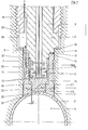
- Fig. 1 which shows a currently preferred embodiment of the ballistic force transducer according to the invention, installed in the cartridge chamber 1 of a typical handgun, 2 denotes a cartridge case which is slightly conical in the axial direction and contains a powder supply 3. After ignition, the powder supply 3 develops explosion gases which lead to an expansion of the cartridge case 2.
- the ballistic force transducer which is arranged in a receiving bore in the cartridge chamber 1, which is essentially not shown in the drawing and extends essentially perpendicular to the central axis of the cartridge case 2, comprises, as shown, a force transmission stamp 4, which has a free lower end face 21 on the outer peripheral surface the cartridge case 2 rests flush and has the task of transmitting the force resulting from the expansion of the cartridge case 2 to a set of detection elements in the form of piezoelectric measuring quartzes 5.
- the force transmission punch 4 has a suitable axial length between its lower end face 21 and its opposite upper end face 13, so that the measuring crystals 5 are held at a suitable distance from the end face 21, and a diameter reduction at its lower end region, so that the end face 21, which rests on the cartridge case 2, has a smaller area dimension than the end face 13, on which the measuring quartz 5 are supported. As a result, the pressure acting on the measuring quartz 5 is reduced.
- the measuring quartzes 5 are clamped with their opposite end faces, as shown, between the upper end face 13 of the force transmission ram 4 and the lower end face 7 by an upper transducer base part 6, with which the ballistic force transducer is fixed in the cartridge chamber 2.
- the measuring quartzes are preferably transverse quartz crystals with a special cut, which is described in detail in German patent specification 22 08 023, so that reference is expressly made to this.
- two such measuring crystals 5, e.g. are isolated from each other by an air gap, provided in the form of two half rings lying concentrically to the central axis of the force transducer.
- the spiral spring 8 is used to dissipate the negative charges on the inner surfaces of the measuring quartz 5, while the positive charges arising on the outer surfaces of the measuring quartz 5 are dissipated to ground via an adapter sleeve 11 formed on the force transmission stamp 4.
- the clamping sleeve 11 extends, as shown, from the outer edge region of the end face 13 of the force transmission stamp 4 in the direction of the transducer base part 6 and surrounds the measuring quartzes 5 outside.
- the clamping sleeve 11 has the task, in addition to the charge dissipation, to pair the measuring quartzes 5 between the end faces 7 and 13 of the transducer base part 6 or force transmission stamp 4, and for this purpose is at its upper end at 12 on a shoulder surface of the transducer base part 6 welded under pretension. By prestressing the measuring quartzes 5, any gap elasticities that may be present are eliminated or reduced.
- the force transmission stamp 4 is, as shown, surrounded concentrically on the outside by an outer sleeve 16, which is welded to a shoulder surface 14 of the base part at 17 at its upper end 15 facing the base part 6.
- the lower end of the outer sleeve 16 forms an annular end face 22 which, like the end face 21 of the force transmission plunger 4, lies flush on the outer surface of the cartridge case 2.
- annular gap 23 with a suitable width D of a few tenths of a millimeter remains between the inner circumferential surface of the lower thickened end region of the outer sleeve 16 facing the end surface 22 and the relevant section of the outer circumference of the force transmission stamp 4.
- This annular gap 23 is connected to an upper enlarged annular space 24 between the outer sleeve 16 and the power transmission ram 4, and this annular space 24 is in turn connected to an annular space which is provided between the upper part of the inner surface of the outer sleeve 16 and the outer peripheral surface of the clamping sleeve 11 .
- the latter is provided with a through hole 25, which creates a connection between an axial groove made in the outer circumference of the outer sleeve 16 and the annular space between the outer sleeve 16 and the clamping sleeve 11.
- the axial groove in the outer circumference of the outer sleeve 16 is aligned with an axial groove 26 in the outer circumference of the sensor base part 6, so that gases or foreign substances, such as grease, entering the thin annular gap 23 can escape to the outside according to the arrows E in FIG. 1.
- the transducer base part 6 sits with an outer ring flange formed thereon on a shoulder 18 in the receiving bore in the cartridge chamber 1, and a threaded ring 19 screwed into the upper section of the receiving bore presses the flange on the transducer base part 6 against the shoulder 18 with its lower end face 20 in this way, the ballistic force transducer according to the invention is fixed in the receiving bore of the cartridge chamber 1.
- the sensor base part 6, although not shown in FIG. 1, preferably has two diametrically opposite axial grooves 26 on its outer circumference for reasons which will be discussed in more detail in connection with FIG. 2.
- FIG. 2 shows a modified design of the ballistic force transducer according to FIG. 1, the same parts as in FIG. 1 having the same reference numerals.
- the embodiment according to FIG. 2 is characterized by the provision of an adapter element 28, which is used in particular when the ballistic force transducer is to be used in the case of large, heavy weapons with large wall thicknesses in the area of the cartridge chamber 1.
- the adapter element 28 mediates a good repositioning of the end faces 21 and 22 of the transducer in relation to this.
- Cartridge storage 1 or the cartridge case 2 in the event that the transducer has to be repeatedly installed and removed for maintenance or renewed calibration purposes.
- the adapter element 28 is fixed in position in the cartridge chamber 1 by means of a wedge 27 which is seated in correspondingly opposite grooves in the cartridge chamber 1 or adapter element 28.
- a threaded ring 29 can be screwed into a threaded bore in a casing surrounding the cartridge chamber 1 and presses the adapter element 28 against the wedge 27 or the bottom 30 of the bore in the cartridge chamber 1.
- An adjusting screw 31 with a conical front part is screwed into a threaded bore in the adapter element 28 and engages with its conical front part in one of the two diametrically opposite axial grooves 26, cf. .Fig. 1, in order to fix the base part 6 of the force transducer in a certain position relative to the cartridge chamber 1.
- the axial groove 26 which is in engagement with the adjusting screw 31 therefore only has an aligning function, while the opposite axial groove 26, as described in connection with FIG. 1, also serves to discharge the gases or greases entering the annular gap 23 to the outside atmosphere.
- the remaining structure of the ballistic force transducer according to FIG. 2 therefore corresponds to FIG. 1.
- the end faces 21 and 22 which lie on the outer surface of the cartridge case 2 should be adapted exactly to the circumferential and axial (conical) course of the cartridge case 2.
- the reaming out of cartridge chambers is a common practice in weapon technology, for which the necessary equipment and tools are commercially available.
- the spring stiffnesses or spring constants of the power transmission ram 4 and the outer sleeve 16 are matched to one another with respect to deflection at a specific surface pressure exerted on their end faces 21 and 22 such that both parts carry out the same or approximately the same deflection paths.
- FIGS. 3a to 3f. 3a and 3b show ballistic force transducers without the provision of an outer sleeve surrounding the force transmission stamp, while FIGS. 3c to 3e relate to a force transducer according to the invention.
- 3a shows the conditions as they exist in a force transducer of known construction immediately after the cartridge case has been expanded, but still in the unloaded state of the cartridge chamber 1.
- the force transmission stamp 32 nestles seamlessly against the cartridge case 2.
- 3b shows the conditions at a high pressure within the cartridge case 2 of, for example, 3000 bar.
- the cartridges sleeve 2 therefore slightly stands out from the power transmission punch 32, so that the annular wedge-shaped cross-section 34 is formed between sleeve 2 and punch 32.
- the result of this annular gap 34 is that the original contact area between the stamp and the cartridge case, determined by the diameter D 0 of the force transmission stamp 32, is correspondingly reduced, cf. Diameter D of the reduced contact area shown in FIG. 3b.
- This quadratic error hereinafter called a, is reproducible and could be taken into account in the calibration.
- the extent of the reduction in diameter from D 0 in FIG. 3a to D p in FIG. 3b depends strongly on the rigidity of the cartridge case used, so that the square error a can turn out differently from case to case.
- the manufacturers of the ballistic force transducers known to date therefore provide for static pressure calibration with a gas or a liquid on the weapon in question, which is specifically matched to the respective application conditions.
- static pressure calibration can be caused, for example, by the type of printing task, with others Errors are up to 30% and is therefore undesirable.
- the outer sleeve 16 and the force transmission ram 4 recede as a result of the expansion of the cartridge sleeve 2 in relation to the bore of the cartridge chamber 1.
- the dimensions of the end faces 21 and 22 and the elasticities of the outer sleeve 16 and the power transmission ram 4 are matched to one another in the manner according to the invention, the relative displacement of the two parts to one another is almost zero.
- the calibration force T in FIG. 5 is introduced via a housing 47 with a recess for the passage of a cable 46, which leads to an amplifier and a recording device.
- the outer sleeve 16 must be somewhat oversized in terms of its wall thickness before the aforementioned tuning, so that a factor K that is too small is initially obtained. Then, the outer sleeve 16 is carefully turned off at the intermediate point H 41 of its outer circumference shown in FIG. 1, as a result of which the factor K increases until the reduction ratio K mentioned above is reached. This ensures that the force on the transfer stamp 4 and the outer sleeve 16 is evenly distributed, i.e. the same surface pressure prevails everywhere.
- the clamping conditions in the basic adjustment of the ballistic force transducer according to the invention do not quite correspond to the installation conditions in a weapon because of the influence of the cartridge case 2, since the Influence of the deformation 33 of the cartridge sleeve which occurs at the transition point between the cartridge chamber 1 and the outer sleeve 16 according to FIG. 3d has not yet been taken into account.
- This deformation 33 which, unlike the known force transducer according to FIG. 3a, does not directly affect the force transmission ram, is, as mentioned above, responsible for the quadratic error a.
- the correction factor f then becomes greater than 1, for example 1.045. It is thereby achieved that the power transmission stamp 4 is not only a recess relative to the outer sleeve 16 according to FIG. 3d experiences a continuous increase in pressure, but z. B.
- the deviation b from the linearity no longer follows the curve 49 in FIG. 3f, but the dashed curve 43.
- the one-sided displacement error b can be reduced by an order of magnitude by this measure, so that it can be neglected for practical purposes.
- the user of the measuring arrangement only needs to make the final adjustment of the end faces 21, 22 of the outer sleeve 16 and force transmission ram 4 to the curvature of the cartridge chamber 1 with a cartridge reamer.
- the force transmission stamp 4 is shortened more than the outer sleeve 16 on average.
- the basic adjustment of the elasticities of these parts is somewhat disturbed depending on the radius of the bore in the cartridge chamber 1 and the dimension of the outer sleeve 16 and force transmission stamp 4, which can be seen in one Stiffening of the power transmission stamp 4 by a value of approximately 0.5% can affect conventional infantry ammunition.
- the correction factor f must be reduced accordingly, for example from 1.045 to 1.04, or the above-mentioned correction factor k for the calibration constant must be increased from, for example, 0.955 to 0.96.
- piezoelectric force transducer for ballistic measurements in typical handguns.
- the values given refer to cartridge cases made of brass or similarly stiff material, which are typical infantry ammunition with a conical medium Outside diameter of 8.6 mm.
- the basic dimensions of the ballistic sensor used were:
- the invention provides a ballistic force transducer which offers the user the essential advantage that he does not require a static calibration test to be carried out on the firearm in question, but rather can be supplied by the manufacturer with predetermined calibration curves.
- the force response sensitivity of a piezo quartz is thus influenced by the type of force application. ⁇
- Ballistic force transducers of a known type mostly use measuring crystals using the piezoelectric longitudinal effect, which are arranged very close to the cartridge case 2. Be between the measuring quartz and the cartridge case in the true sense there is no longer a power transmission stamp, but only a thickened partition or membrane on which the curvature of the cartridge case is incorporated.
- Inhomogeneities on the contact surface of such force transducers on the cartridge case therefore manifest themselves directly as inhomogeneities in the force distribution on the measuring quartzes and, depending on the type of inhomogeneity, for example edge pressure or support in the middle, cause different sensitivity to force.
- the introduction of force onto the measuring quartzes is homogenized, so that the end faces 7 and 13 of the sensor base part 6 and force transmission stamp 4 apply uniform pressure to them.
- semi-ring-shaped measuring quartzes 5 are preferably used for the transducer using the piezoelectric transverse effect, the frontal contact surfaces between the quartzes and the transducer components enclosing them are inherently smaller than when longitudinal quartzes are provided, so that a further homogenization of the force flow through the measuring quartzes is achieved becomes.
- transverse quartz crystals Another advantage achieved with the use of transverse quartz crystals is their higher sensitivity (by the factor, length / radius of the quartz crystals) to longitudinal quartz crystals. Furthermore, it is possible to provide the transverse quartz with a cut whose resistance to high stress and high temperature due to the suppression of the so-called Dauphine twin formation is significantly better than with longitudinal quartzes with an X-cut, cf. the German patent specification 22 08 032 and "Piezoelectric measurement technology" from J. Tichy and G. Gautschi, Springer-Verlag 1980, page 107 ff.
- the cross-sectional expansion of the force transmission stamp 4 in the region of its end face 13 which is in engagement with the measuring quartz 5 has the advantage that the force resulting from the pressurization of the active end face 21 of the force transmission stamp 4 manifests itself in a lower surface pressure of the measuring quartz 5.
- higher explosion pressures can therefore be measured in the cartridge case than in the case of transducers of conventional design.
- M essquarze can provide 5 higher stiffness results in a higher natural frequency of the pickup system and thus a lower sensitivity to acceleration forces.
- the reduction in the charge sensitivity caused by the reduction of the active end face 21 of the force transmission stamp 4 compared to the contact surface 13 for the quartz is of no practical importance, since ballistic measurements always have very high pressures and thus high piezoelectric charges are generated in any case.
- Another advantage that results from the fact that the measuring quartz 5 is set back by the relatively long force transmission stamp 4 is that the temperature effects, in particular temperature transients, which frequently interfere with ballistic measurements, are substantially alleviated.
- the invention makes it possible to provide a force transducer for ballistic pressure measurements, which preferably acts in a piezoelectric manner and which emits signals which are very well reproducible, even if it is used by a user who is not particularly familiar with measurement technology. Since the sensitivity no longer depends on many randomnesses during installation, as before, the user can directly convert the measurement signal given by the sensor into a certain pressure value using the calibration factor provided by the manufacturer, whereby only the pressure threshold value P R necessary for the initial expansion of the cartridge case must be added. This pressure threshold can be calculated with sufficient accuracy from the diameter and wall thickness of the cartridge case.
- the invention was previously described in connection with ballistic pressure measurements on firearms. However, it goes without saying that it is not limited to this application, but can be used for static and dynamic pressure measurements in a similarly advantageous manner where, for certain reasons, the pressure does not act directly on the force transmission element of the transducer, but instead via an expansion element.
- a piezoelectric detection element in the form of one or more, preferably partially ring-shaped transverse quartz crystals is currently preferred, longitudinal quartz crystals or, if necessary, with appropriate adjustment of the force application, can only be provided with piezoelectric measuring crystals that respond to shear forces.
- detection element also includes a suitably polarized piezoceramic and other materials that react piezoelectrically when subjected to a force, electrical resistance elements, in particular strain gauges and piezoresistive elements with semiconductors, and the like.
Abstract
Description
Die Erfindung betrifft einen Kraftaufnehmer, insbesondere für ballistische Druckmessungen, mit einem dem zu messenden Druck an seiner einen Stirnfläche unterworfenen Kraftübertragungselement, einem zwischen Kraftübertragungselement und einem Aufnehmerbasisteil unter Vorspannung gehaltenen Erfassungelement sowie einer das Kraftübertragungselement aussen umgebenden und dem zu messenden Druck stirnseitig ausgesetzten Aussenhülse, sowie ein Verfahren zu seiner Herstellung.The invention relates to a force transducer, in particular for ballistic pressure measurements, with a force transmission element subjected to the pressure to be measured on its one end face, a detection element held under tension between the force transmission element and a transducer base part, and an outer sleeve surrounding the force transmission element and exposed to the pressure to be measured on the end face, and a process for its manufacture.
Verschiedene Verfahren und Messanordnungen zur Ermittlung der Höhe und des zeitlichen Ablaufes der in einer Patronenhülse entwickelten Drücke sind bekannt. Eine bekannte Vorgehensweise sieht die Verwendung von sog. Kupfer-Crushers (Kupfer-Stauchzylindern) vor. Hierzu wird die Patronenhülse angebohrt und werden die Verbrennungsgase in einen-Zylinder mit einem Kolben geleitet. Der Kolben drückt auf ein zylindrisches Kupferstück, das je nach Höhe der Drücke des Verbrennungsgases mehr oder weniger gestaucht wird. Die Aufweitung des Durchmessers oder die Verkürzung der Länge des Kupferstückes gibt einen Aufschluss über die Höhe des Druckes in der Patronenhülse. Diese Methode dient zu Vergleichsversuchen; sie gibt keinen Aufschluss über die jeweilig herrschenden Spitzendrücke, da die Stauchung nicht nur vom Spitzendruck, sondern auch von der Einwirkungszeit des Druckes abhängt. Einen besseren Aufschluss über den Druckverlauf erhält man, wenn der Druck in der angebohrten Patronenhülse auf einen piezoelektrischen Hochdruckaufnehmer übertragen wird. Es lässt sich dann der gesamte zeitliche Verlauf des Druckes an einem Oszillographen aufzeichnen, so dass sowohl der Spritzendruck als auch der Druckanstieg und Druckabfall genau quantitativ bestimmt werden können. Beide Methoden haben den systematischen Fehler, dass hierfür die Patronenhülse angebohrt werden muss.Various methods and measuring arrangements for determining the level and the time sequence of the pressures developed in a cartridge case are known. A known procedure provides for the use of so-called copper crushers (copper upsetting cylinders). For this purpose, the cartridge case is drilled and the combustion gases are passed into a cylinder with a piston. The piston presses on a cylindrical piece of copper, which is more or less compressed depending on the pressure of the combustion gas. The widening of the diameter or the shortening of the length of the copper piece provides information about the amount of pressure in the cartridge case. This method is used for comparison tests; it does not provide any information about the prevailing peak pressures, since the compression depends not only on the peak pressure, but also on the exposure time to the pressure. A better understanding of the pressure curve can be obtained if the pressure in the drilled cartridge case is transferred to a piezoelectric high-pressure sensor. The entire time course of the pressure can then be recorded on an oscillograph, so that both the syringe pressure and the pressure increase and pressure drop can be precisely determined quantitatively. Both methods have the systematic error that this does the cartridge case must be drilled.
Abgesehen von den durch die Anbohrung bedingten-Gasverlusten in der Patronenhülse bzw. dem Patronenlager bedeutet der erforderliche Verbindungskanal zum Kraftaufnehmer ein zusätzliches Volumen, und ist der Druckaufbau wegen des grösseren Volumens hinter der Patronenhülse weniger hoch. Die gemessenen Spitzendrücke entsprechen damit nicht den wirklichen Drücken in der Patronenhülse.Apart from the gas losses in the cartridge case or the cartridge chamber caused by the drilling, the required connection channel to the force transducer means an additional volume, and the pressure build-up is less high because of the larger volume behind the cartridge case. The measured peak pressures therefore do not correspond to the real pressures in the cartridge case.
Eine andere Methode sieht die Messung des Druckes unmittelbar in der Aufnahmebohrung des Patronenlagersvor, in die die Patronenhülse eingeführt wird. Die Anbohrung der Patronenhülse kann damit vermieden werden. Abgesehen davon, dass sich auch hierbei wegen des Zusatzvolumens ein Messfehler einstellt, hat diese Methode den Nachteil, dass bis zu dem Zeitpunkt, an dem das Projektil die Aufnahmebohrung verlässt, kein Messignal erhalten wird. Der Druckaufbau im Inneren der Patronenhülse während der ersten Phase der Verbrennung ist daher nicht bestimmbar, und die plötzliche Freigabe des Messkanals zum Kraftaufnehmer durch das Projektil täuscht einen zu steilen Druckanstieg vor.Another method involves measuring the pressure directly in the receiving bore of the cartridge chamber into which the cartridge case is inserted. The drilling of the cartridge case can be avoided. In addition to the fact that a measurement error occurs due to the additional volume, this method has the disadvantage that no measurement signal is received until the projectile leaves the mounting hole. The pressure build-up inside the cartridge case during the first phase of the combustion cannot therefore be determined, and the sudden release of the measuring channel to the force transducer by the projectile simulates an excessively steep pressure increase.
Aus den US-Patentschriften 3 886 792 und 3 960 018 ist weiter ein piezoelektrischer Kraftaufnehmer für ballistische Druckmessungen bekannt, der sich auf dem Schaft der Patronenhülse über eine Membran abstützt, so dass die aus der elastischen und plastischen Aufweitung der Patronenhülse resultierenden Kräfte auf den Aufnehmer übertragen werden. Der Aufnehmer wird zu diesem Zweck in einer Bohrung im Patronenlager eingebaut, und die mit der Aussenfläche der Patronenhülse in Berührung kommende Membran ist so-gestaltet, dass sie eine Fortsetzung des durch die Ausbohrung des Patronenlagers weggeschnittenen Teils der Patronenlagerbohrung bildet. Der Gasdruck in der Patronenhülse dehnt diese etwas aus, so dass die Kraft über die Patronenhülse und die Membran am Kraftaufnehmer auf die in diesem angeordneten piezoelektrischen Messquarze übertragen wird. Deren elektrische Ladung wird zu einem Elektrometer oder Ladungsverstärker geführt. Diese bekannte Methode hat den Vorteil, dass der Verbrennungsablauf und die Strömungsverhältnisse der Gase durch die Messeinrichtung praktisch nicht gestört werden, und weiter ist es möglich, auch Serienmessungen i vorzusehen, da keine besonderen Messvorbereitungen für die einzelnen Schüsse notwendig sind. Ein Nachteil dieser bekannten Anordnungen besteht jedoch darin, dass es sehr schwierig ist, die druckaufnehmende Vorderpartie des Kraftaufnehmers genau an die Bohrung im Patronenlager bzw. an den Aussenumfang der Patronenhülse anzupassen.From US Pat. Nos. 3,886,792 and 3,960,018, a piezoelectric force transducer for ballistic pressure measurements is also known, which is supported on the shaft of the cartridge case via a membrane, so that the forces resulting from the elastic and plastic expansion of the cartridge case onto the sensor be transmitted. For this purpose, the sensor is installed in a bore in the cartridge chamber, and the membrane that comes into contact with the outer surface of the cartridge case is designed in such a way that it is a continuation of the bore through the cartridge forms part of the cartridge chamber bore cut away. The gas pressure in the cartridge case expands it somewhat, so that the force is transmitted via the cartridge case and the membrane on the force transducer to the piezoelectric measuring quartzes arranged in it. Their electrical charge is led to an electrometer or charge amplifier. This known method has the advantage that the combustion process and the flow conditions of the gases are practically not disturbed by the measuring device, and it is also possible to provide series measurements i, since no special measurement preparations for the individual shots are necessary. A disadvantage of these known arrangements, however, is that it is very difficult to adapt the pressure-receiving front part of the force transducer exactly to the bore in the cartridge chamber or to the outer circumference of the cartridge case.
Vom messtechnischen Standpunkt betrachtet, sollte der Zusammenhang zwischen dem Gasdruck in der Patronenhülse und der abgegebenen piezoelektrischen Ladung möglichst linear sein. Zwar ist der Piezoeffekt an sich sehr linear, doch wirkt sich der Druck in der Patronenhülse wegen der komplizierten Übertragung auf die Messquarze nicht in einer proportionalen Kraft aus. Da eine Patronenhülse im Patronenlager stets ein gewisses Spiel haben muss, damit sie mühelos eingeschoben oder herausgeworfen werden kann, liegt von daher schon eine gewisse Diskontinuität vor, wenn die Patronenhülse durch den Verbrennungsdruck aufgeweitet wird und sich innen an die Bohrung im Patronenlager anschmiegt. Bis zu diesem Zeitpunkt wirkt sich der Gasdruck nur im Inneren der Patronenhülse, jedoch nicht auf den Kraftaufnehmer aus. Die erste Phase bis zur Anlage der Patronenhülse an der Vorderpartie des Kraftaufnehmers wird daher nicht ermittelt. Die Druckanzeige bis zu diesem Zeitpunkt ist Null. Um den effektiven Druck zu erhalten, muss daher der anfängliche Patronenaufweitungsdruck dem gemessenen Druck hinzugezählt werden, was jedoch vom messtechnischen Standpunkt keine Probleme bereitet.From a metrological point of view, the relationship between the gas pressure in the cartridge case and the piezoelectric charge emitted should be as linear as possible. Although the piezo effect is very linear in itself, the pressure in the cartridge case does not have a proportional force due to the complicated transfer to the measuring quartz. Since a cartridge case must always have a certain amount of play in the cartridge chamber so that it can be easily inserted or ejected, there is therefore a certain discontinuity when the cartridge case is expanded by the combustion pressure and nestles inside the bore in the cartridge chamber. Up to this point, the gas pressure only affects the interior of the cartridge case, but not the force transducer. The first phase until the cartridge case touches the front of the Kraft sensor is therefore not determined. The pressure display up to this point is zero. In order to obtain the effective pressure, the initial cartridge expansion pressure must therefore be added to the measured pressure, but this does not pose any problems from a measurement point of view.
Wie die Erfahrung zeigt, wird die Patronenhülse bei Abfeuerung des Schusses stets plastisch verformt und bleibt nach dem Schuss aufgeweitet. Wenn die Vorderpartie des Kraftaufnehmers,die sich auf der Patronenhülse abstützt, also Teil der Bohrung im Patronenlager ist, in diese hineinragt, steigt die vom Kraftaufnehmer abgegebene Kurve Q = f(P) zunächst steil an, weil die Patronenhülse zunächst nur auf den Kraftaufnehmer drückt,und fällt dann - ab, sobald bei höheren Drücken die Patronenhülse in Anlage an die Bohrung im Patronenlager kommt. Ist die Vorderpartie des Kraftaufnehmers jedoch gegenüber der Patronenlagerbohrung etwas zurückversetzt, so verbleibt zwischen Patronenhülse und Vorderpartie des Kraftaufnehmers ein Spalt. Erst bei höheren Drücken beult sich die Patronenhülse im Bereich des Kraftaufnehmers soweit aus, dass eine Berührung mit diesem zustande kommt. In diesem Fall ergibt sich je nach Ausmass der Zurückversetzung der Vorderpartie des Kraftaufnehmers ein mehr oder minder grosser Bereich, in dem kein Messignal vom Aufnehmer abgegeben wird. Die genaue Formanpassung der Vorderpartie des Kraftaufnehmers an die jeweilige Konfiguration der Patronenhülse ist nicht nur von Bedeutung für die Grösse des Bereiches, ab dem der Kraftaufnehmer anspricht, sondern auch für die Reproduzierbarkeit der Messung, da schon geringe Inhomogenitäten zu Diskontinuitäten in der Kraftverteilung auf die Messquarze führen können.As experience shows, the cartridge case is always plastically deformed when the shot is fired and remains expanded after the shot. If the front part of the force transducer, which is supported on the cartridge case, i.e. is part of the bore in the cartridge chamber, protrudes into it, the curve Q = f (P) emitted by the force transducer initially rises steeply because the cartridge case initially only presses on the force transducer , and then - falls off as soon as the cartridge case comes into contact with the bore in the cartridge chamber at higher pressures. However, the V partie order of the load cell relative to the cartridge chamber bore slightly recessed, so the load cell there remains a gap between the cartridge case and front part. Only at higher pressures does the cartridge case bulge in the area of the force transducer to such an extent that it comes into contact with it. In this case, depending on the extent of the setback of the front part of the force transducer, there is a more or less large area in which no measurement signal is emitted by the transducer. The exact shape adaptation of the front part of the force transducer to the respective configuration of the cartridge case is not only important for the size of the area from which the force transducer responds, but also for the reproducibility of the measurement, since even small inhomogeneities to discontinuities in the force distribution on the measuring quartz being able to lead.
Infolge dieser Umstände wird bei den vorgenannten US-Patentschriften vorgeschlagen, dass man die durch die Membran gebildete Vorderpartie des Kraftaufnehmers durch Unterlegscheiben an die Konfiguration der Patronenlagerbohrung anpasst. Abgesehen davon, dass solche Justierungsmassnahmen umständlich und für den Kunden unerwünscht sind, ergeben sich nicht die erforderlichen Anlagegenauigkeiten von wenigen Mikrometern, so dass nach wie vor gewisse Kantenpressungen und dgl. verbleiben. Dies hat zur Folge, dass dem Verwender des Kraftaufnehmers keine vorgegebene Eichkurve zur Verfügung gestellt werden kann, die sich ohne weitere Massnahmen an der Anwendungsstelle zur Messauswertung verwenden lässt. Vielmehr erfordern die bekannten piezoelektrischen Kraftaufnehmer für ballistische Messungen stets, dass der Verwender an der jeweiligen Feuerwaffe eine statische Kalibrierung mit einem Gas oder einer Flüssigkeit vornimmt, d.h. eine individuelle Eich- oder Kalibrierkurve erstellt. Dies ist neben den erwähnten Umständen deshalb auch erforderlich, weil die Steifigkeit eines Kraftaufnehmers stets kleiner als diejenige des Patronenlagers ist, so dass bei der Aufweitung der Patronenhülse Kraftaufnehmer und Patronenlager unterschiedliche Verformungen erfahren, d.h. die Membran des Kraftaufnehmers gegenüber dem Aussenumfang der Patronenlagerbohrung zurückversetzt wird. Die entstandene Einsenkung hat zur Folge, dass.die Patronenhülse nicht mehr, wie bei der Eichung vorausgesetzt, vollständig an der Vorderfläche der Membran anliegt, sondern sich die Anlagefläche je nach Umfang der Einsenkung mehr oder minder verkleinert. Die aus den veränderten Anlageverhältnissen resultierende geringere Kraft auf die Messquarze äussert sich in einer von Fall zu Fall unterschiedlichen Abweichung vom linearen Verlauf der Eichkurve. Im Ergebnis muss bei den bekannten Kraftaufnehmem somit stets eine auf den bestimmten Anwendungsfall gezielt abgestimmte Kalibrierkurve aufgestellt werden, die jedoch in der Regel,bedingt durch die Art der stati- schen Aufbringung des Eichdruckes, mit zum Teil erheblichen Fehlern behaftet sein kann.As a result of these circumstances, it is proposed in the aforementioned US patents that the front part of the force transducer formed by the membrane be adapted to the configuration of the cartridge chamber bore by means of washers. Apart from the fact that such adjustment measures are cumbersome and undesirable for the customer, the required system accuracies of a few micrometers do not result, so that certain edge pressures and the like remain. The result of this is that the user of the force transducer cannot be provided with a predetermined calibration curve that can be used for measuring evaluation without any further measures at the application site. Rather, the known piezoelectric force transducers for ballistic measurements always require that the user carries out a static calibration with a gas or a liquid on the respective firearm, ie creates an individual calibration or calibration curve. In addition to the circumstances mentioned, this is also necessary because the stiffness of a force transducer is always lower than that of the cartridge chamber, so that when the cartridge case is expanded, the force transducer and the cartridge chamber experience different deformations, ie the membrane of the force transducer is set back relative to the outer circumference of the cartridge chamber bore. The resultant depression means that the cartridge case no longer lies completely against the front surface of the membrane, as required for calibration, but the contact surface is reduced more or less depending on the extent of the depression. The lower force on the measuring quartzes resulting from the changed system conditions manifests itself in a deviation from the linear course of the calibration curve that differs from case to case. As a result, the known force absorption mem thus always one on the particular application specifically tuned calibration be set up, but in general, due to the nature of the stati - specific application of calibration pressure, may be subject to significant part failures.
Bei den bekannten piezoelektrischen Kraftaufnehmern sind weiter die Messquarze sehr nahe an der druckausgesetzten Membran angeordnet, was neben einer schlechten Kraftverteilung auf die Messquarze den Nachteil hat, dass diese thermisch stark belastet werden.In the known piezoelectric force transducers, the measuring quartzes are further arranged very close to the membrane exposed to pressure, which, in addition to poor force distribution over the measuring quartzes, has the disadvantage that these are subjected to high thermal loads.
Demgegenüber liegt der Erfindung die Aufgabe zugrunde, einen Kraftaufnehmer der eingangs erwähnten Gattung sowie ein Verfahren zu seiner Herstellung zu schaffen, der seitens des Herstellers mit einer für sämtliche jeweiligen Anwendungsfälle zutreffenden Eichkurve bereitgestellt werden kann.In contrast, the invention has for its object to provide a force transducer of the type mentioned and a method for its production, which can be provided by the manufacturer with a calibration curve applicable to all respective applications.
Erfindungsgemäss wird diese Aufgabe dadurch gelöst, dass die Federsteifigkeit der Aussenhülse auf die Federsteifigkeit des unabhängig von der Aussenhülse dem zu messenden Druck stirnseitig ausgesetzten Kraftübertragungselementes so abgestimmt ist, daß die Aussenhülse in annähernd dem gleichen Ausmass wie das Kraftübertragungselement dem einwirkenden Druck in Axialrichtung des Aufnehmers nachgibt.According to the invention, this object is achieved in that the spring stiffness of the outer sleeve is matched to the spring stiffness of the force transmission element exposed to the pressure to be measured independently of the outer sleeve so that the outer sleeve yields to approximately the same extent as the force transmission element to the pressure acting in the axial direction of the transducer .
Das erfindungsgemässe Verfahren zur Herstellung . eines Kraftaufnehmers mit dem eingangs erwähnten Grundaufbau zeichnet sich dadurch aus, dass man in einem ersten Schritt die Kraftansprechempfindlichkeit E1 des Kraftübertragungselementes alleine bestimmt, dann aussen um das Kraftübertragungselement eine Aussenhülse so anordnet und am Aufnehmerbasisteil befestigt, dass deren dem Druck ausgesetzte Stirnfläche mit der Stirnfläche des Kraftübertragungselementes fluchtet, in einem zweiten Schritt die Kraftansprechempfindlichkeit E2 dieser Anordnung bestimmt und in einem dritten Schritt die Wandstärke der Aussenhülse soweit reduziert, bis die Beziehung
Durch die Erfindung wird somit ein piezoelektrischer Kraftaufnehmer für ballistische Messungen geschaffen, der sich ebenso wie die vorbeschriebenen bekannten Anordnungen mit seiner Vorderpartie auf dem Aussenumfang der Patronenhülse abstützt. Anders als bei den bekannten Anordnungen findet die Abstützung jedoch nicht nur am Kraftübertragungselement, sondern auch an der dieses Kraftübertragungselement umgebenden Aussenhülse statt, wobei die Aussenhülse ebenso wie das Kraftübertragungselement bei einem auf seine Stirnfläche einwirkenden Druck gestaucht wird. Da die Federkonstanten'oder Federsteifigkeiten beider Teile gezielt aufeinander abgestimmt sind, erfahren sie im wesentlichen die gleichen Stauchungen mit der Folge, dass zwischen Aussenhülse und Kraftübertragungselement keine oder nur sehr geringe Relativverschiebungen eintreten. Die aus der Stauchung des Kraftaufnehmers resultierende vergrösserte Verformung der Patronenhülse im Bereich der Vorderpartie des Aufnehmers wirkt sich daher hinsichtlich der veränderten Anlageflächen im wesentlichen nur auf die Aussenhülse, nicht dagegen auf das Kraftübertragungselement aus, so dass an dessen Stirnfläche die Patronenhülse auch bei Aufweitung weiterhin voll anliegt. Die auf die Einwirkung des Druckes auf die gesamte Stirnfläche des Kraftübertragungselementes bezogene Eichkurve entspricht daher dem von dem Erfassungselement abgegebenen Signal bei einem durch die Aufweitung der Patronenhülse auf das Kraftübertragungselement ausgeübten Druck. Aus diesem Grund kann auf eine Kalibrierung durch den verwender des erfindungsgemässen Kraftaufnehmers verzichtet werden,bzw. der Hersteller ist in der Lage, den Kraftaufnehmer mit einer vorgegebenen Eichkurve bereitzustellen. Der Messaufwand wird hierdurch erheblich reduziert und gleichzeitig die Reproduzierbarkeit der Messung erhöht, da der Verwender die Anpassung der Vorderpartie des Kraftaufnehmers an die jeweilige Konfiguration des druckführenden Teils, an dem der Aufnehmer angeordnet wird, infolge der erfindungsgemässen Konstruktion selbst vornehmen kann, ohne dass hierdurch die vorgegebene Eichkurve nennenswert beeinflusst wird. Aus der deutschen Offenlegungsschrift 25 16 120 ist zwar ein piezoelektrischer Kräft- aufnehmer mit einer das Kraftübertragungselement umgebenden Hülse bekannt, doch hat diese nur die Aufgabe, das Kraftübertragungselement nach aussen hin abzuschirmen und zu führen.The invention thus creates a piezoelectric force transducer for ballistic measurements, which, like the known arrangements described above, is supported with its front part on the outer circumference of the cartridge case. In contrast to the known arrangements, the support does not only take place on the force transmission element, but also on the outer sleeve surrounding this force transmission element, the outer sleeve as well as the force transmission element being compressed at a pressure acting on its end face. Since the spring constants or spring stiffnesses of the two parts are specifically coordinated with one another, they experience essentially the same upsetting, with the result that no or only very slight relative displacements occur between the outer sleeve and the force transmission element. The increased deformation of the cartridge case in the region of the front part of the sensor resulting from the compression of the force sensor therefore affects only the outer sleeve with regard to the changed contact surfaces and not, however, the force transmission element so that the cartridge case is still fully in contact with its face, even when expanded. The calibration curve relating to the action of the pressure on the entire end face of the force transmission element therefore corresponds to the signal emitted by the detection element at a pressure exerted on the force transmission element by the expansion of the cartridge case. For this reason, calibration by the user of the force transducer according to the invention can be dispensed with, or. the manufacturer is able to provide the force transducer with a specified calibration curve. This considerably reduces the measurement effort and at the same time increases the reproducibility of the measurement, since the user can adapt the front part of the force transducer to the respective configuration of the pressure-carrying part on which the transducer is arranged as a result of the construction according to the invention, without this predefined calibration curve is significantly influenced. Namely, from the German Offenlegungsschrift 25 16 120, a piezoelectric Kräft - transducer with a sleeve surrounding the Kraftübertragungselemen t known, but this has only the task of the power transmission member to the outside to shield out and lead.
Bezüglich Weiterbildungen der'Erfindung wird auf die Unteransprüche verwiesen.With regard to further developments of the invention, reference is made to the subclaims.
Eine Ausführungsform der Erfindung wird nachfolgend anhand der Zeichnung näher erläutert. Es zeigen:
- Fig. 1 eine geschnittene Ansicht von einem erfindungsgemäss aufgebauten piezoelektrischen Kraftaufnehmer, eingebaut in eine Handfeuerwaffe,
- Fig. 2 eine modifizierte Ausbildung des Kraftaufnehmers nach Fig. 1 zur Verwendung bei Feuerwaffen mit grossem Kaliber,
- Fig. 2a einen Schnitt, längs der Schnittlinie II-II in Fig. 2,
- Fig. 3a schematische Darstellungen bezüglich der Anlage-und 3b verhältnisse zwischen einer Patronenhülse und einem Kraftübertragungselement bei Aufnehmern herkömmlicher Bauart,
- Fig. 3c schematische Darstellungen bezüglich der Anlagebis 3e verhältnisse zwischen einer Patronenhülse und dem Kraftübertragungselement bei einem erfindungsgemässen Kraftaufnehmer mit Aussenhülse,
- Fig. 3f eine grafische Darstellung bezüglich des Verlaufes der Abweichungen von der linearen Beziehung bei einem Kraftaufnehmer herkömmlicher Bauart und einem Kraftaufnehmer nach der Erfindung,
- Fig. 4 eine grafische Darstellung bezüglich der von dem piezoelektrischen-Erfassungselement abgegebenen Ladung in Abhängigkeit vom Druck auf das Kraftübertragungselement bei einem Kraftaufnehmer herkömmlicher Bauart und einem Kraftaufnehmer nach der Erfindung,
- Fig. 5 eine schematische Ansicht von einer Anordnung zur Eichung und Abstimmung eines Kraftaufnehmers nach der Erfindung.
- 1 is a sectional view of a piezoelectric force transducer constructed according to the invention, installed in a handgun,
- 2 shows a modified design of the force transducer according to FIG. 1 for use with firearms with a large caliber,
- 2a shows a section along the section line II-II in FIG. 2,
- 3a shows schematic representations with regard to the system and 3b relationships between a cartridge case and a force transmission element in transducers of conventional design,
- 3c schematic representations with respect to the system bis 3e relationships between a cartridge case and the force transmission element in a force transducer according to the invention with an outer sleeve,
- 3f is a graphical representation of the course of the deviations from the linear relationship in a force transducer of conventional design and a force transducer according to the invention,
- 4 shows a graphical representation with regard to the charge emitted by the piezoelectric detection element as a function of the pressure on the force transmission element in the case of a force transducer of a conventional type and a force transducer according to the invention,
- Fig. 5 is a schematic view of an arrangement for calibrating and tuning a force transducer according to the invention.
In der nachfolgenden Beschreibung beziehen sich die Ausdrücke "unten" und "oben" auf die in der Zeichnung wiedergegebene Lage des ballistischen Kraftaufnehmers nach der Erfindung.In the following description, the terms "below" and "above" refer to the position of the ballistic force transducer according to the invention shown in the drawing.
In Fig. 1, die eine gegenwärtig bevorzugte Ausführungsform des ballistischen Kraftaufnehmers nach der Erfindung,eingebaut in das Patronenlager 1 einer typischen Handfeuerwaffe, zeigt, ist mit 2 eine in Axialrichtung leicht konisch verlaufende Patronenhülse bezeichnet, die einen Pulvervorrat 3 enthält. Der Pulvervorrat 3 entwickelt nach Zündung Explosionsgase, die zu einer Aufweitung der Patronenhülse 2 führen.In Fig. 1, which shows a currently preferred embodiment of the ballistic force transducer according to the invention, installed in the
Der in einer in der Zeichnung nicht näher bezeichneten Aufnahmebohrung im Patronenlager 1, die sich im wesentlichen senkrecht zur Mittelachse der Patronenhülse 2 erstreckt, angeordnete ballistische Kraftaufnehmer umfasst, wie dargestellt, einen Kraftübertragungsstempel 4, der mit seiner einen freien unteren Stirnfläche 21 auf der äusseren Umfangsfläche der Patronenhülse 2 bündig aufliegt und die Aufgabe hat, die aus der Aufweitung der Patronenhülse 2 resultierende Kraft auf einen Satz Erfassungsclemente in Form von piezoelektrischen Messquarzen 5 zu übertragen. Der Kraftübertragungsstempel 4 hat erfinungsgemäss, sc wohl eine geeignete axiale Länge zwischen seiner unteren Stirnfläche 21 und seiner gegenüberliegenden oberen Stirnfläche 13, so dass die Messquarze 5 in einem geeigneten Abstand von der Stirnfläche 21 gehalten sind, als auch eine Durchmesserreduzierung an seinem unteren Endbereich, so dass die Stirnfläche 21, die auf der Patronenhülse 2 aufliegt, eine kleinere Flächenabmessung als die Stirnfläche 13 aufweist, auf der sich die Messquarze 5 abstützen. Hierdurch wird eine Verringerung des auf die Messquarze 5 einwirkenden Drucks erreicht.The ballistic force transducer, which is arranged in a receiving bore in the
Die Messquarze 5 sind mit ihren gegenüberliegenden Endflächen, wie dargestellt, zwischen der oberen Stirnfläche 13 des Kraftübertragungsstempels 4 und der unteren Stirnfläche 7 von einem oberen Aufnehmerbasisteil 6 eingeklemmt, mit dem der ballistische Kraftaufnehmer im Patronenlager 2 fixiert wird. Aus noch zu erläuternden Gründen handelt es sich bei den Messquarzen vorzugsweise um Transversalquarze mit einem speziellen Schnitt, der im Detail in der deutschen Patentschrift 22 08 023 näher beschrieben ist, so dass hierauf ausdrücklich Bezug genommen wird. Bei der gezeigten Ausführungsform sind zwei derartige Messquarze 5, die z.B. durch einen Luftspalt gegeneinander isoliert sind, in Gestalt von zwei konzentrisch zur Mittelachse des Kraftaufnehmers liegenden Halbringen vorgesehen. Diese bilden zusammen einen Innenraum, in dem ein die entstehende piezoelektrische..Ladung an den metallisierten Innenoberflächen der Messquarze 5 ableitendes Element, z.B. in Gestalt einer Spiralfeder 8, angeordnet ist. Die Spiralfeder 8 steht über eine durch eine zentrale Bohrung im Aufnehmerbasisteil 6 geführte Leitung 9 in Verbindung mit einem in Fig. 2 gezeigten Anschlusstecker 10.The measuring
Die Spiralfeder 8 dient der Ableitung der negativen Ladungen an den inneren Oberflächen der Messquarze 5, während die an den äusseren Oberflächen der Messquarze 5 entstehenden positiven Ladungen über eine am Kraftübertragungsstempel 4 angeformte Spannhülse 11 an Masse abgeleitet werden. Die Spannhülse 11 erstreckt sich, wie dargestellt, vom äusseren Randbereich der Stirnfläche 13 des Kraftübertragungsstempels 4 in Richtung auf das Aufnehmerbasisteil 6 und umgibt aussen die Messquarze 5. Die Spannhülse 11 hat neben der Ladungsableitung die Aufgabe, das Paar Messquarze 5 zwischen den Stirnflächen 7 und 13 von Aufnehmerbasisteil 6 bzw. Kraftübertragungsstempel 4 zusammenzupressen, und ist zu diesem Zweck an ihrem oberen Ende bei 12 an einer Absatzfläche des Aufnehmerbasisteils6 unter Vorspannung angeschweisst. Durch die Vorspannung der Messquarze 5 wird erreicht, dass eventuell vorhandene Spaltelastizitäten beseitigt oder verringert werden.The spiral spring 8 is used to dissipate the negative charges on the inner surfaces of the measuring
Der Kraftübertragungsstempel 4 wird erfindungsgemäss, wie dargestellt, von einer Aussenhülse 16 konzentrisch aussen umgeben, die an ihrem oberen dem Basisteil 6 zugewandten Ende 15 an einer Absatzfläche 14 des Basisteils bei 17 angeschweisst ist. Das untere Ende der Aussenhülse 16 bildet eine ringförmige Stirnfläche 22, die ebenso wie die Stirnfläche 21 des Kraftübertragungsstempels 4 auf der Aussenoberfläche der Patronenhülse 2 bündig aufliegt.According to the invention, the
Zwischen der inneren Umfangsfläche des unteren,der Stirnfläche 22 zugewandten verdickten Endbereiches der Aussenhülse 16 und dem betreffenden Abschnitt des Aussenumfangs des Kraftübertragungsstempels 4 verbleibt erfindungsgemäss ein Ringspalt 23 mit einer geeigneten Breite D von wenigen zehntel Millimetern. Dieser Ringspalt 23 steht in Verbindung mit einem oberen erweiterten Ringraum 24 zwischen Aussenhülse 16 und Kraftübertragungsstempel 4, und dieser Ringraum 24 steht wiederum in Verbindung mit einem Ringraum, der zwischen dem oberen Teil der Innenoberfläche der Aussenhülse 16 und der äusseren Umfangsfläche der Spannhülse 11 vorgesehen ist. An einer geeigneten Stelle im oberen Abschnitt der Aussenhülse 16 ist diese mit einer Durchgangsbohrung 25 versehen, die eine Verbindung zwischen einer im Aussenumfang der Aussenhülse 16 eingebrachten Axialnut und dem Ringraum zwischen Aussenhülse 16 und Spannhülse 11 herstellt. Die Axialnut im Aussenumfang der Aussenhülse 16 ist zu einer Axialnut 26 im Aussenumfang des Aufnehmerbasisteils 6 ausgerichtet, so dass in den dünnen Ringspalt 23 eintretende Gase oder Fremdstoffe, wie Fett, nach aussen gemäss der Pfeile E in Fig. 1 entweichen können.According to the invention, an
Das Aufnehmerbasisteil 6 sitzt mit einem daran angeformten äusseren Ringflansch auf einer Schulter 18 in der Aufnahmebohrung im Patronenlager 1 auf,und ein in den oberen Abschnitt der Aufnahmebohrung eingeschraubter Gewindering 19 drückt mit seiner unteren Stirnfläche 20 den Flansch am Aufnehmerbasisteil 6 gegen die Schulter 18. Auf diese Weise wird der ballistische Kraftaufnehmer nach der Erfindung in der Aufnahmebohrung des Patronenlagers 1 fixiert. Darauf hinzuweisen ist, dass das Aufnehmerbasisteil 6, obschon in Fig. 1 nicht gezeigt, an seinem äusseren Umfang vorzugsweise zwei diametral gegenüberliegende Axialnuten 26 aus Gründen aufweist, auf die in Verbindung mit Fig. 2 näher eingegangen wird.The
Fig. 2 zeigt eine modifizierte Ausbildung des ballistischen Kraftaufnehmers nach Fig. 1, wobei gleiche Teile wie in Fig. 1 das gleiche Bezugszeichen tragen. Die Ausführung nach Fig. 2 zeichnet sich durch das Vorsehen eines Adapterelementes 28 aus, welches insbesondere dann Verwendung findet, wenn der ballistische Kraftaufnehmer bei grossen schweren Waffen mit grossen Wandstärken im Bereich des Patronenlagers 1 eingesetzt werden soll. Das Adapterelement 28 vermittelt eine gute Wiederpositionierung der Stirnflächen 21 und 22 des Aufnehmers in Bezug auf-das. Patronenlager 1 bzw. die Patronenhülse 2 für den Fall, dass der Aufnehmer zu Wartungs- oder erneuten Kalibrierungszwecken wiederholt ein- und ausgebaut werden muss.FIG. 2 shows a modified design of the ballistic force transducer according to FIG. 1, the same parts as in FIG. 1 having the same reference numerals. The embodiment according to FIG. 2 is characterized by the provision of an
Wie insbesondere Fig. 2a zeigt, wird das Adapterelement 28 im Patronenlager 1 durch einen Keil 27 lagemässig fixiert, der in entsprechendmgegenüberliegendenNuten im Patronenlager 1 bzw. Adapterelement 28 einsitzt. Ein Gewindering 29 kann in eine Gewindebohrung in einem das Patronenlager 1 umgebenden Mantel eingeschraubt werden und presst das Adapterelement 28 gegen den Keil 27 bzw. den Boden 30 der Bohrung im Patronenlager 1. Eine Stellschraube 31 mit einem konischen Vorderteil ist in einer Gewindebohrung im Adapterelement 28 eingeschraubt und greift mit ihrem konischen Vorderteil in eine der beiden diametral gegenüberliegenden Axialnuten 26, vgl.Fig. 1, ein, um das Basisteil 6 des Kraftaufnehmers in einer bestimmten Stellung relativ zum Patronenlager 1 zu fixieren. Die mit der Stellschraube 31 in Eingriff befindliche Axialnut 26 hat daher nur ausrichtende Funktion, während die gegenüberliegende Axialnut 26, wie in Verbindung mit Fig. 1 beschrieben, weiterhin der Ableitung der in den Ringspalt 23 eintretenden Gase oder Fette an die Aussenatmosphäre dient. Der übrige Aufbau des ballistischen Kraftaufnehmers nach Fig. 2 entspricht demnach Fig. 1.2a, the
Aus Gründen, die nachfolgend deutlich werden,sollten die Stirnflächen 21 und 22, die auf der Aussenoberfläche der Patronenhülse 2 aufliegen, genau dem umfänglichen und axialen (konischen) Verlauf der Patronenhülse 2 angepasst sein. Dies wird erfindungsgemäss dadurch erreicht, dass man die Stirnflächen 21 und 22 vor Einbau des Aufnehmers in die Waffe zunächst plan ausbildet und etwas in die Bohrung im Patronenlager hineinragen lässt. Nach Fixierung des Aufnehmers im Patronenlager 1 wird dann in dessen die Hülse 2 aufnehmenden Bohrung eine Reibahle eingeführt und das überstehende Material-an Aussenhülse 16 und Kraftübertragungsstempel 4 solange ausgerieben, bis die in Fig. 1 gezeigte bündige Konfiguration der Stirnflächen 21 und 22 vorliegt. Das Ausreiben von Patronenlagern ist eine in der Waffentechnik übliche Handlung, wozu die notwendigen Einrichtungen und Werkzeuge im Handel erhältlich sind.For reasons which will become clear below, the end faces 21 and 22 which lie on the outer surface of the
Erfindungsgemäss sind die Federsteifigkeiten bzw. Federkonstanten von Kraftübertragungsstempel 4 und Aussenhülse 16 gegenüber einem Einfedern bei einem auf ihre Stirnflächen 21 bzw. 22 ausgeübten spezifischen Flächendruck dergestalt aufeinander abgestimmt, dass beide Teile gleiche oder annähernd gleiche Einfederungswege vornehmen. Dies sei anhand von Fig. 3a bis 3f näher erläutert. Fig. 3a und 3b zeigen dabei ballistische Kraftaufnehmer ohne Vorsehen von einer den Kraftübertragungsstempel umgebenden Aussenhülse, während Fig. 3c bis 3e einen Kraftnehmer nach der Erfindung betreffen.According to the invention, the spring stiffnesses or spring constants of the
Wie schon eingangs erwähnt, ist es nicht möglich, einen Kraftübertragungsstempel, in-Fig. 3a mit 32 bezeichnet, so auszubilden, dass seine Steifigkeit in Axialrichtung ebenso gross wie diejenige des Patronenlagers 1 bei einer Aufweitung der Patronenhülse 2 ist. Der Kraftübertragungsstempel 32 gibt also bei einer einwirkenden Druckbelastung stets etwas nach und bildet gegenüber dem Patronenlager 1 eine Vertiefung. Diese Vertiefung ist Ursache für wesentliche Unlinearitäten im Verlauf der Eichkurve Q = f (P) mit Q = Ladung und P = Verbrennungsdruck in der Patrone. Die infolge der gebildeten Vertiefung auftretende Verformung 33 an der Patronenhülse 2 gemäss Fig. 3b lässt zwischen der Stirnfläche des Kraftübertragungsstempels 32 und der Aussenfläche der Patronenhülse 2 einen Ringspalt 34 entstehen. Fig. 3a zeigt demgegenüber die Verhältnisse, wie sie bei einem Kraftaufnehmer bekannter Konstruktion unmittelbar nach dem Aufweiten der Patronenhülse, jedoch noch im unbelasteten Zustand des Patronenlagers 1 vorliegen. In diesem Zustand schmiegt sich der Kraftübertragungsstempel 32 lückenlos an die Patronenhülse 2 an. Fig. 3b zeigt die Verhältnisse bei einem hohen Druck innerhalb der Patronenhülse 2 von z.B. 3000bar. Die Patronenhülse 2 hebt sich daher vom Kraftübertragungsstempel 32 umfänglich etwas ab, so dass der im Querschnitt keilförmige Ringspalt 34 zwischen Hülse 2 und Stempel 32 entsteht. Dieser Ringspalt 34 hat zur Folge, dass die durch den Durchmesser D0 des Kraftübertragungsstempels 32 bestimmte ursprüngliche Berührungsfläche zwischen Stempel und Patronenhülse in entsprechender Weise verkleinert wird, vgl. Durchmesser D der in Fig. 3b gezeigten reduzierten Berührungsfläche. Da die Berührungsfläche die Angriffsfläche des Druckes ist, wird der Übertragungsfaktor des Druckes auf das Erfassungselement des Aufnehmers bzw. die Messquarze ebenfalls verringert. Mit anderen Worten: der ursprüngliche Kalibrierfaktor des Aufnehmers fällt ab. Es entsteht dadurch anstelle des in Fig. 4 gezeigten linearen Zusammenhanges zwischen der Ladung Q und dem Druck P (Kurve 38) ein degressiver Kurvenverlauf, vergleiche Kurve 37 in Fig. 4. Eine solche nicht lineare Kalibrierkurve 37 ist unerwünscht, gefordert wird die Gerade 38. Zwischen der Einfederung oder Stauchung h des Kraftübertragungsstempels und der abgegebenen piezoelektrischen Ladung Q besteht ein analoger Zusammenhang, so dass die Kurven 37 und 38 in Fig. 4 ebenfalls das Verhältnis h = f(P) unter den genannten Bedingungen wiedergeben.As already mentioned at the beginning, it is not possible to use a force transmission stamp, in FIG. 3a with 32, so that its rigidity in the axial direction is as great as that of the
Der Verlauf der nicht linearen Kalibrierkurve 37 in Fig. 4 lässt sich durch folgende Gleichungen darstellen:

- h = effektive Stauchung des Kraftübertragungsstempels,
- h = Stauchung des Kraftübertragungsstempels bei auf seiner gesamten Stirnfläche gleichmässig einwirkendem Druck Pmax,
- Q = von den Messquarzen abgegebene effektive Ladung bei einem Druck P
- Q = von den Messquarzen abgegebene Ladung bei auf der gesamten Stirnfläche des Kraftübertragungsstempels einwirkendem Druck Pmax,
- P = Druck
- P = Maximaldruck max
- PH = Druck, der zur Aufweitung der Patronenhülse notwendig ist,
- u = Koeffizient für die quadratische Abweichung von der Linearität.
- h = effective compression of the power transmission ram,
- h = compression of the force transmission ram with pressure P max acting uniformly over its entire end face,
- Q = effective charge emitted by the measuring quartz at a pressure P
- Q = max by the measuring quartz given charge at inwirkendem on the entire face of the power transmission punch e pressure P
- P = pressure
- P = maximum pressure max
- P H = pressure required to widen the cartridge case,
- u = coefficient for the quadratic deviation from linearity.
Eine ideale Kalibrierkurve würde nur den linearen Term in Gleichungen (1) und (2) enthalten, während der quadratische Term die Abweichung von der Linearität darstellt und Folge der veränderten Anlageverhältnisse zwischen Kraftübertragungsstempel und Patronenhülse ist.An ideal calibration curve would only contain the linear term in equations (1) and (2), while the quadratic term represents the deviation from linearity and is the result of the changed contact conditions between the power transmission stamp and the cartridge case.
Dieser quadratische Fehler, im folgenden a genannt, ist zwar gut reproduzierbar und könnte bei der Eichung mit berücksichtigt werden. Das Ausmass der Durchmesserverringerung von D0 in Fig. 3a auf Dp in Fig. 3b hängt jedoch stark von der Steifigkeit der jeweilig verwendeten Patronenhülse ab, so dass der quadratische Fehler a in entsprechender Weise von Fall zu Fall unterschiedlich ausfallen kann. Die Hersteller der bisher bekannten ballistischen Kraftaufnehmer sehen daher vor, eine statische,auf die jeweiligen Anwendungsbedingungen gezielt abgestimmte Druckeichung mit einem Gas oder einer Flüssigkeit an der betreffenden Waffe vorzunehmen. Eine solche statische Druckeichung kann jedoch z.B. durch die Art der Druckaufgabe bedingt, mit weiteren Fehlern bis zu 30 % behaftet sein und ist daher unerwünscht.This quadratic error, hereinafter called a, is reproducible and could be taken into account in the calibration. The extent of the reduction in diameter from D 0 in FIG. 3a to D p in FIG. 3b depends strongly on the rigidity of the cartridge case used, so that the square error a can turn out differently from case to case. The manufacturers of the ballistic force transducers known to date therefore provide for static pressure calibration with a gas or a liquid on the weapon in question, which is specifically matched to the respective application conditions. However, such a static pressure calibration can be caused, for example, by the type of printing task, with others Errors are up to 30% and is therefore undesirable.
Bei dem erfindungsgemässen ballistischen Kraftaufnehmer kann dagegen auf eine solche Kalibrierung mit einem Gas oder einer Flüssigkeit verzichtet werden. Dies ist Folge des zusätzlichen Vorsehens der abgestimmten Aussenhülse 16, welche das Auftreten des quadratischen Fehlers a als auch Fehler höherer Ordnung weitgehend verhindert. Dies sei anhand von Fig. 3c und _3d erläutert. Im schwach belasteten Zustand der Patronenhülse 2 liegen gemäss Fig. 3c infolge des Ausreibens des Patronenhalgers 1 die Stirnflächen von Aussenhülse 16 und Kraftübertragungsstempel 4 bündig koextensiv auf der Aussenfläche der Patronenhülse 2 an. Unter höherem Druck gemäss Fig. 3d weichen die Aussenhülse 16 und der Kraftübertragungsstempel 4 infolge der Aufweitung der Patronenhülse 2 gegenüber der Bohrung des Patronenlagers 1 zurück. Da jedoch die Abmessungen der Stirnflächen 21 und 22 sowie die Elastizitäten von Aussenhülse 16 und Kraftübertragungsstempel 4 in der erfindungsgemässen Weise aufeinander abgestimmt sind, ist die Relativverschiebung der beiden Teile zueinander nahezu Null.With the ballistic force transducer according to the invention, however, such a calibration with a gas or a liquid can be dispensed with. This is due to the additional provision of the coordinated
Man erreicht diese Abstimmung zweckmässigerweise dadurch, dass man an einem Prüfstand eine Kraftempfindlichkeitprüfung vor Einbau des Aufnehmers in das Patronenlager durchführt, d.h. bevor die Stirnflächen 21 und 22 von Aussenhülse 16 und Kraftübertragungsstempel 4 an die Wölbung der Patronenhülse 2 angepasst sind. Zunächst wird die Kraftempfindlichkeit E1 des Kraftübertragungsstempels 4 alleine, d.h. ohne Aussenhülse 16, bestimmt. Dann wird der gesamte Aufnehmer zusammen mit der Aussenhülse 16 gemäss Fig. 5 gegen die plane Oberfläche 39 eines Stahlblockes 40 gedrückt und die sich dann ergebende Kraftempfindlichkeit E2 ermittelt. Eine erfindungsgemässe Abstimmung der Federsteifigkeiten von Aussenhülse 16 und Kraftübertragungsstempel 4 liegt vor, wenn:![]()

- F1 = Grösse der Stirnfläche des Kraftübertragungsstempels 4
- F2 = Grösse der Stirnfläche der Aussenhülse 16,
- f = Korrekturfaktor (wird noch erläutert).
- F 1 = size of the end face of the
power transmission stamp 4 - F 2 = size of the end face of the
outer sleeve 16, - f = correction factor (to be explained).
Die Einleitung der Kalibrierkraft T in Fig. 5 erfolgt über ein Gehäuse 47 mit einer Aussparung für die Durchführung eines Kabels 46, das zu einem Verstärker und einem Aufzeichnungsgerät führt.The calibration force T in FIG. 5 is introduced via a
Die Aussenhülse 16 muss vor der genannten Abstimmung hinsichtlich ihrer Wandstärke etwas überdimensioniert sein, damit zunächst ein zu kleiner Faktor K erhalten wird. Dann wird die Aussenhülse 16 an der in Fig. 1 gezeigten zwischenliegenden Stelle H 41 ihres Aussenumfanges vorsichtig abgedreht, wodurch der Faktor K ansteigt, bis das oben angeführte Reduktionsverhältnis K erreicht ist. Danach ist gewährleistet, dass die Kraft auf den Ubertragungsstempel 4 und die Aussenhülse 16 gleichmässig verteilt vorliegt, d.h. überall die gleiche Flächenpressung herrscht.The
Die Einspannverhältnisse beim grundlegenden Abgleich des ballistischen Kraftaufnehmers nach der Erfindung entsprechen wegen des Einflusses der Patronenhülse 2 nicht ganz den Einbauverhältnissen in einer Waffe, da der Einfluss der sich an der Übergangsstelle zwischen Patronenlager 1 und Aussenhülse 16 gemäss Fig. 3d einstellenden Verformung 33 der Patronenhülse noch nicht berücksichtigt ist. Diese Verformung 33, die sich anders als bei dem bekannten Kraftaufnehmer gemäss Fig. 3a nicht direkt auf den Kraftübertragungsstempel auswirkt, ist, wie oben erwähnt, verantwortlich für den quadratischen Fehler a. Infolge der Verformung 33 der Patronenhülse 2 bzw. der Bildung des relativ grossen Ringspaltes 34 wird die theoretisch gleich grosse Einfederung oder Stauchung von Aussenhülse 16 und Kraftübertragungsstempel 4 nicht ganz erreicht; es entsteht vielmehr eine leichte Relativverschiebung zwischen Kraftübertragungsstempel 4 und Aussenhülse 16 (vgl. Fig. 3d), so dass an der Übergangsstelle zwischen Kraftübertragungsstempel 4 und Aussenhülse 16 ein Ringspalt 42 auftritt, der jedoch wesentlich kleiner als der Ringspalt 34 an der Verformungsstelle 33 der Patronenhülse 2 ist und daher einen entsprechend geringeren Einfluss auf die Abweichung von der linearen Eichkurve hat. Die durch den Ringspalt 42 hervorgerufene Reduktion der Druckangriffsfläche am Kraftübertragungsstempel 4 bedingt eine Abweichung von der linearen Eichkurve,im folgenden b genannt, die um eine Grössenordnung kleiner als die vorgenannte Abweichung a ist und,. wie sich rechnerisch zeigen lässt, in der 4..Potenz vom Druck P abhängt.The clamping conditions in the basic adjustment of the ballistic force transducer according to the invention do not quite correspond to the installation conditions in a weapon because of the influence of the
Der Verlauf dieser Abweichung b = f(P) bei einem typischen ballistischen Kraftaufnehmer nach der Erfindung mit einem Verhältnis des Aussendurchmessers der Aussenhülse 16 zum Aussendurchmesser des Kraftübertragungsstempels 4 von 2:1 und f = 1 in Gleichung (3) ist in Fig. 3f durch die ausgezogene Kurve 49 wiedergegeben. Zum Vergleich zeigt die strichpunktierte Kurve 44 in Fig. 3f den Verlauf der quadratischen Abweichung a = f(P) bei einem Aufnehmer herkömmlicher Bauart.The course of this deviation b = f ( P ) in a typical ballistic force transducer according to the invention with a ratio of the outside diameter of the
Mit der erfindungsgemässen Massnahme des Vorsehens einer auf das Einfederungsverhalten des Kraftübertragungsstempels 4 gezielt abgestimmten Aussenhülse 16 alleine lässt sich somit ein weitgehender Angleich der effektiven Kurve Q = f(P) an die lineare Kurve erreichen.With the measure according to the invention of providing an
Wie nachfolgend gezeigt werden wird, kann die Annäherung an den linearen Verlauf Q = f(P) weiter dadurch verbessert werden, dass man statt mit einem Korrekturfaktor f = 1, d.h. gleich hoher Flächenpressung auf die Aussenhülse 16 und den Kraftübertragungsstempel 4, letzteren etwas,z.B. um 4,5 %,steifer als die Aussenhülse 16 ausbildet. Der Korrekturfaktor f wird dann grösser als 1, z.B. 1,045. Dadurch wird erreicht, dass der Kraftübertragungsstempel 4 bei einer kontinuierlichen Druckerhöhung nicht nur eine Einsenkung gegenüber der Aussenhülse 16 gemäss Fig. 3d erfährt, sondern z.B. bei P = 0,4 P max über die Stirnfläche 22 der Aussenhülse 16 etwas hervorragt, während bei P = 0,8 Pmax die Stirnflächen der beiden Teile 4,16 miteinander fluchten und sich bei P ? 0,8 Pmax wieder eine Einsenkung des Kraftübertragungsstempels 4 gegenüber der Aussenhülse 16 einstellt, vgl. Fig. 3e.As will be shown below, the approximation to the linear profile Q = f (P) can be further improved by instead of using a correction factor f = 1, that is to say the same surface pressure on the
Unter diesen Voraussetzungen folgt die Abweichung b von der Linearität nicht mehr der Kurve 49 in Fig. 3f, sondern der gestrichelten Kurve 43. Anstelle eines in einer Richtung sich durchgehend auswirkenden Verschiebungsfehlers b erhält man einen Verschiebungsfehler ±g, der sich während eines ersten Abschnitts in einer positiven und während eines zweiten Abschnittes in einer negativen Abweichung von der linearen Kurve Q = f(P) äussert. Der einseitige Verschiebungsfehler b kann durch diese Massnahme um eine Grössenordnung herabgesetzt werden, so dass er für praktische Zwecke vernachlässigt werden kann.Under these conditions, the deviation b from the linearity no longer follows the
Darauf hinzuweisen ist, dass anstelle der Rechnung mit einem Korrekturfaktor f > 1 bzw. 1,045 ähnliche Ergebnisse auch dadurch erhalten werden können, dass man unter Beibehaltung von f = 1 die Steigung der linearen Kurve so verändert, dass sie quasi eine Mittelung der effektiven Kurve Q = f(P) darstellt. Mit anderen Worten: man multipliziert den Druckkalibrierungsfaktor Q/P, der sich aus der Kraftkalibrierung gemäss Fig. 5 ergibt, mit einem Faktor k L 1, z.B. 0,955 (entsprechend einer Verringerung von 4',5 %). Hierdurch wird der Fehler b zwar nicht verringert, jedoch längs der verschobenen linearen Eichkurve in Plus- und Minusrichtung verteilt. Das letztgenannte Verfahren läuft darauf hinaus, eine parabelförmig verlaufende Kurve durch eine Gerade anzunähern.It should be noted that instead of the calculation with a correction factor f> 1 or 1.045, similar results can also be obtained by changing the slope of the linear curve while maintaining f = 1 in such a way that it effectively averages the effective curve Q = f (P). In other words: multiply the pressure calibration factor Q / P, which results from the force calibration according to FIG. 5, by a
Nachdem der ballistische Kraftaufnehmer nach der Erfindung in der beschriebenen Weise abgestimmt worden ist, braucht der Verwender der Messanordnung nur noch mit einer Patronenlagerreibahle die endgültige Anpassung der Stirnflächen 21, 22 von Aussenhülse 16 und Kraftübertragungsstempel 4 an die Krümmung des Patronenlagers 1 vorzunehmen. Durch das Ausreiben wird der Kraftübertragungsstempel 4 im Mittel dabei stärker verkürzt als die Aussenhülse 16. Die erfolgte Grundabstimmung der Elastizitäten dieser Teile wird dadurch je nach Radius der Bohrung im Patronenlager 1 und der Abmessung von Aussenhülse 16 und Kraftübertragungsstempel 4 etwas gestört, was sich in einer Versteifung des Kraftübertragungsstempels 4 um einen Wert von ca. 0,5 % bei herkömmlicher Infanteriemunition auswirken kann. Wegen dieses Effektes ist der Korrekturfaktor f entsprechend zu reduzieren, z.B. von 1,045 auf 1,04, bzw. der obengenannte Korrekturfaktor k für die Kalibrierkonstante von z.B. 0,955 auf 0,96 heraufzusetzen. Darauf hinzuweisen ist, dass der Wert für den Versteifungseffekt des Kraftübertragungsstempels 4 infolge der Ausreibung von dessen Stirnfläche 21, der mit 0,5 % angegeben wurde, solange zutrifft, wie das Verhältnis von Durchmesser der Patronenhülse zu Durchmesser und Länge des Kraftübertragungsstempels 4 annähernd gleichbleibt. Wenn man einen erfindungsgemässen Kraftaufnehmer für ballistische Messungen bei grosskalibrigen Feuerwaffen, wie Kanonen,verwandet, ohne gleichzeitig den Aufnehmer selbst zu vergrössern, würde das genannte Verhältnis zwischen den Abmessungen von Kraftaufnehmer und Patronenhülse wesentlich kleiner werden. Dementsprechend ist auch der aus dem Ausreiben resultierende Versteifungsfaktor zu verringern.After the ballistic force transducer according to the invention has been tuned in the manner described, the user of the measuring arrangement only needs to make the final adjustment of the end faces 21, 22 of the
Darauf hinzuweisen ist ferner, dass sowohl bei der bekannten Aufnehmerbauart als auch der erfindungsgemässen durch die Bildung des Ringspaltes 34 bzw. 42 an der Patronenhülse '2 auf den Kraftübertragungsstempel eine Federwirkung nach Art einer Ringfeder ausgeübt wird, welche Kräfte vom Patronenlager 1 bzw. der Aussenhülse 16 auf den Kraftübertragungsstempel überträgt. Diese Federwirkung, die ebenfalls zu einer Abweichung vom linearen Verlauf der Eichkurve führen kann,ist jedoch bei dem erfindungsgemäss aufgebauten Kraftaufnehmer infolge der geringeren Verformung der Patronenhülse 2 am Kraftübertragungsstempel wesentlich kleiner als bei Aufnehmern herkömmlicher Bauart und kann für praktische Messungen vernachlässigt werden.Should be noted further, that both the known Aufnehmerbauart as well as according to the invention by the formation of the
Nachfolgend wird ein Beispiel für einen piezoelektrischen Kraftaufnehmer nach der Erfindung für ballistische Messungen bei Handfeuerwaffen typischer Bauart gegeben. Die angegebenen Werte beziehen sich auf Patronenhülsen aus Messing oder ähnlich steifem Material, wobei es sich um typische Infanteriemunition mit einem konischen mittleren Aussendurchmesser von 8,6 mm handelt. Der maximale bei Zündung des Pulvervorrates 3 in der Patronenhülse ent- wickelte Druck beträgt Pmax = 3200bar; für die anfängliche Aufweitung der Patronenhülse ist ein Anfangsdruck PH = 200bar erforderlich. Die grundlegenden Abmessungen des verwendeten ballistischen Aufnehmers betrugen:

Bei einem Korrekturfaktor f = 1 in Gleichung (3) beträgt die maximale unidirektionale Abweichung b max von der Linearität 0,63 %, und dieser Wert bmax reduziert sich bei einem Faktor f = 1,045 auf + gmax = 0,02 %. Im Vergleich dazu beträgt die maximale quadratische Abweichung a bei einem ballistischen Kraftaufnehmer herkömmlicher max Art ohne Aussenhülse 5,6 %.In a correction factor f = 1 in equation (3), the maximum un i t i o direct dimensional deviation from linearity b max 0.63%, and this value b max is reduced by a factor f = 1.045 at + g max = 0 , 02%. In comparison, the maximum square deviation a for a ballistic force transducer of a conventional max type without an outer sleeve is 5.6%.
Die maximale Relativverschiebung bei P = Pmax zwischen Aussenhülse 16 und Kraftübertragungsstempel 4, die zur Bildung des Ringspaltes 42 in Fig. 3d führt, beträgt 8,4 µm. Dagegen errechnet sich bei einem Kraftaufnehmer ohne Aussenhülse die Verschiebung zwischen Patronenlager und Kraftübertragungsstempel gemäss Gleichung (1) zu 141,6 µm.The maximum relative displacement at P = P max between the
Infolge der erheblich geringeren Verformung der Patronenhülse 2 an dem die Messkraft übertragenden Aufnehmerteil (Kraftübertragungsstempel) ist der durch die erwähnte Federwirkung der Patronenhülse verursachte Fehler praktisch vernachlässigbar.As a result of the considerably lower deformation of the
Im Ergebnis wird durch die Erfindung ein ballistischer Kraftaufnehmer bereitgestellt, der für den Anwender den wesentlichen Vorteil bietet, dass er keine an der betreffenden Feuerwaffe vorzunehmende statische Eichprüfung erfordert, sondern seitens des Herstellers mit vorgegebenen Eichkurven geliefert werden kann. Das Vorsehen der Aussenhülse 16, die den Kraftübertragungsstempel 4 in geringem Abstand aussen umgibt, führt zu einer höheren Reproduzierbarkeit der Messungen infolge einer besseren Kraftverteilung auf die Messquarze 5. Die oft in Lehrbüchern verbreitete Meinung, wonach die piezoelektrische Empfindlichkeit, z.B. von Quarzen mit Longitudinaleffekt, unabhängig von der Krafteinleitungsfläche und der Abmessung des Quarzes sei, .trifft nur annäherungsweise, nämlich dann zu, wenn sich der Quarz in sämtlichen Koordinatenrichtungen völlig ungehindert verformen kann. Ist dies nicht der Fall, indem z.B. die Verformungen in Y- und Z-Richtung völlig unterdrückt werden, entsteht eine Verringerung der piezoelektrischen Ansprechempfindlichkeit eines Quarzes. In der Praxis hat man in der Regel weder den völlig freien noch den völlig verformungsbehinderten-Zustand.As a result, the invention provides a ballistic force transducer which offers the user the essential advantage that he does not require a static calibration test to be carried out on the firearm in question, but rather can be supplied by the manufacturer with predetermined calibration curves. The provision of the
Die Kraftansprechempfindlichkeit eines Piezoquarzes wird somit von der Art der Krafteinleitung beeinflusst.`Was die Auflage des Kraftübertragungsstempels 4 auf der Oberfläche der Patronenhülse 2 betrifft, ist trotz sorgfältiger Anpassung nicht stets damit zu rechnen, dass ideale Anlageverhältnisse vorliegen. Es genügen vielmehr schon Versetzungen von Bruchteilen von Mikrometern, um u.U. erhebliche Unterschiede in der Belastung von einzelnen Bereichen des Kraftübertragungsstempels 4 zu verursachen. Ballistische Kraftaufnehmer bekannter Bauart verwenden zumeist Messquarze unter Ausnutzung des piezoelektrischen Longitudinaleffektes, die sehr nahe an der Patronenhülse 2 angeordnet sind. Zwischen den Messquarzen und der Patronenhülse befindet sich im eigentlichen Sinne kein Kraftübertragungsstempel mehr, sondern nur eine verdickte Zwischenwand oder Membran, an der die Wölbung der Patronenhülse eingearbeitet ist. Inhomogenitäten an der Auflagefläche solcher Kraftaufnehmer auf der Patronenhülse äussern sich daher unmittelbar als Inhomogenitäten bei der Kraftverteilung auf die Messquarze und bewirken, je nach Art der Inhomogenität, z.B. Kantenpressung oder Auflage in der Mitte, verschiedene Kraftansprechempfindlichkeiten.The force response sensitivity of a piezo quartz is thus influenced by the type of force application. ` As far as the bearing of the
Durch das erfindungsgemässe Vorschalten eines relativ langen Kraftübertragungsstempels 4 und das hierdurch bewirkte Zurückversetzen der Messquarze 5 wird dagegen eine Homogenisierung der Krafteinleitung auf die Messquarze erreicht, so dass diese seitens der Stirnflächen 7 und 13 von Aufnehmerbasisteil 6 und Kraftübertragungsstempel 4 gleichmässig mit Druck beaufschlagt werden. Da erfindungsgemäss für den Aufnehmer vorzugsweise halbringförmige Messquarze 5 unter Ausnutzung des piezoelektrischen Transversaleffektes verwendet werden, sind die stirnseitigen Berührungsflächen zwischen den Quarzen und den sie einschliessenden Aufnehmerbauteilen von Natur her kleiner als bei Vorsehen von Longitudinalquarzen, so dass eine weitere Homogenisierung des Kraftflusses durch die Messquarze erreicht wird.By virtue of the upstream connection of a relatively long
Ein weiterer mit der Verwendung von Transversalquarzen erzielter Vorteil ist deren höhere Empfindlichkeit (um den Faktor, Länge/Radius der Quarze) gegenüber Longitudinalquarzen. Weiter ist es möglich, die Transversalquarze mit einem Schnitt zu versehen, dessen Widerstand gegenüber hoher Belastung und hoher Temperatur infolge der Unterdrückung der sog. Dauphine-Zwillingsbildung wesentlich besser als bei Longitudinalquarzen mit X-Schnitt ist, vgl. hierzu auch die eingangs erwähnte deutsche Patentschrift 22 08 032 sowie "Piezoelektrische Messtechnik" von J. Tichy und G. Gautschi, Springer-Verlag 1980, Seite 107 ff.Another advantage achieved with the use of transverse quartz crystals is their higher sensitivity (by the factor, length / radius of the quartz crystals) to longitudinal quartz crystals. Furthermore, it is possible to provide the transverse quartz with a cut whose resistance to high stress and high temperature due to the suppression of the so-called Dauphine twin formation is significantly better than with longitudinal quartzes with an X-cut, cf. the
Die Querschnittserweiterung des Kraftübertragungsstempels 4 im Bereich von dessen mit den Messquarzen 5 in Eingriff befindlicher Stirnfläche 13 hat den Vorteil, dass sich die aus der Druckbeaufschlagung der aktiven Stirnfläche 21 des Kraftübertragungsstempels 4 ergebende Kraft in einer geringeren Flächenpressung der Messquarze 5 äussert. Mit dem ballistischen Kraftaufnehmer nach der Erfindung können daher höhere Explosionsdrücke in der Patronenhülse gemessen werden als bei Aufnehmern herkömmlicher Bauart. Da hierdurch ferner die Masse des Kraftübertragungsstempels 4 verringert wird und sich andererseits Messquarze 5 höherer Steifigkeit vorsehen lassen, ergibt sich eine höhere Eigenfrequenz des Aufnehmersystems und damit eine geringere Empfindlichkeit gegenüber Beschleunigungskräften. Die durch die Reduktion der aktiven Stirnfläche 21 des Kraftübertragungsstempels 4 gegenüber der Auflagefläche 13 für die Quarze bedingte Verringerung der Ladungsempfindlichkeit ist ohne praktische Bedeutung, da bei ballistischen Messungen stets sehr hohe Drücke vorliegen und damit in jedem Fall hohe piezoelektrische Ladungen erzeugt werden.The cross-sectional expansion of the
Bei ballistischen Kraftaufnehmern herkömmlicher Art mit Abstützung auf der Patronenhülse über eine Membran ergibt sich stets ein Kraftnebenfluss von der Membran in das umgebende Aufnehmergehäuse. Hierdurch können bis zu 50 % der einwirkenden Druckkräfte an den Messquarzen vorbeigeleitet werden. Auch andere Einflüsse, z.B. Reibung oder Verklemmung, Leckgase oder Fette, die in das Patronenlager gedrückt werden, haben derartige kraftableitende Wirkungen. Bei der Erfindung können sich derartige Kraftnebenschlüsse hingegen nicht oder in nur weit geringerem Umfang auswirken, da der Kraftübertragungsstempel 4 völlig unabhängig von den umgebenden Bauteilen des Kraftaufnehmers elastisch nachgeben kann, so dass die aus dem erwähnten Kraftnebenschlüssenresultierenden Fehlersignale nicht mehr auftreten. Die während der Verbrennung des Pulvervorrates 3 in der Patronenhülse 2 verdrängten Leckgase im Patronenlager 1 sowie eventuell darin befindliche Fette oder dgl. können leicht durch den Ringspalt 23 zwischen Aussenhülse 16 und Kraftübertragungsstempel 4 an die Aussenatmosphäre entweichen und damit keinen seitlichen Druck auf die dünne Spannhülse 11 ausüben. Ein solcher seitlicher Druck auf die Spannhülse 11 würde sich ebenfalls messwertverfälschend auf die Messquarze 5 auswirken.In conventional ballistic force transducers with support on the cartridge case via a membrane, there is always a secondary force flow from the membrane into the surrounding transducer housing. In this way, up to 50% of the compressive forces acting on the measuring quartz can be conducted. Other influences, such as friction or jamming, leakage gases or greases, which are pressed into the cartridge chamber have such force-dissipating effects. In the case of the invention, however, force shunts of this type cannot have an effect, or can only have a far smaller effect, since the
Ein weiterer sich aus der durch den relativ langen Kraftübertragungsstempel 4 erzielten Zurückversetzung der Messquarze 5 ergebender Vorteil liegt darin, dass die bei ballistischen Messungen häufig störenden Temperaturauswirkungen, insbesondere Temperaturtransienten, wesentlich gemildert werden.Another advantage that results from the fact that the measuring
Zusammengefasst ermöglicht die Erfindung die Bereitstellung eines, vorzugsweise auf piezoelektrischem Wege wirkenden Kraftaufnehmers für ballistische Druckmessungen,der sehr gut reproduzierbare Signale abgibt, auch wenn er von einem nicht speziell mit der Messtechnik vertrauten Benutzer verwendet wird. Da die Empfindlichkeit nicht mehr, wie bisher, von vielen Zufälligkeiten beim Einbau abhängt, kann der Benutzer mittels des vom Hersteller mitgegebenen Eichfaktors das vom Aufnehmer abgegebene Messignal in einen bestimmten Druckwert direkt umrechnen, wobei lediglich der für das anfängliche Aufweiten der Patronenhülse notwendige Druckschwellenwert PR hinzuaddiert werden muss. Dieser Druckschwellenwert lässt sich mit ausreichender Genauigkeit aus dem Durchmesser und der Wandstärke der Patronenhülse berechnen.In summary, the invention makes it possible to provide a force transducer for ballistic pressure measurements, which preferably acts in a piezoelectric manner and which emits signals which are very well reproducible, even if it is used by a user who is not particularly familiar with measurement technology. Since the sensitivity no longer depends on many randomnesses during installation, as before, the user can directly convert the measurement signal given by the sensor into a certain pressure value using the calibration factor provided by the manufacturer, whereby only the pressure threshold value P R necessary for the initial expansion of the cartridge case must be added. This pressure threshold can be calculated with sufficient accuracy from the diameter and wall thickness of the cartridge case.
Vorausgehend wurde die Erfindung in Verbindung mit ballistischen Druckmessungen an Feuerwaffen beschrieben. Es versteht sich jedoch, dass sie auf diesen Anwendungsfall nicht beschränkt ist, sondern für statische und dynamische Druckmessungen überall dort ähnlich vorteilhaft verwendet werden kann, wo der Druck aus bestimmten Gründen nicht direkt, sondern über ein Aufweitungselement auf das Kraftübertragungselement des Aufnehmers einwirkt. Obschon, wie vorbeschrieben, ein piezoelektrisches Erfassungselement in Form von-ein oder mehreren,vorzugsweise teilringförmigen Transversalquarzen gegenwärtig bevorzugt wird, können auch Longitudinalquarze oder gegebenenfalls unter entsprechender Anpassung der Krafteinleitung nur auf Scherkräfte piezoelektrisch ansprechende Messquärze vorgesehen werden. Der Begriff "Erfassungselement" schliesst ferner eine in geeigneter Weise polarisierte Piezokeramik sowie andere bei Einwirkung einer Kraft piezoelektrisch reagierende Materialien, elektrische Widerstandselemente, insbesondere auch Dehnungsmesstreifen und piezoresistive Elemente mit Halbleiter, und dgl. ein.The invention was previously described in connection with ballistic pressure measurements on firearms. However, it goes without saying that it is not limited to this application, but can be used for static and dynamic pressure measurements in a similarly advantageous manner where, for certain reasons, the pressure does not act directly on the force transmission element of the transducer, but instead via an expansion element. Although, as described above, a piezoelectric detection element in the form of one or more, preferably partially ring-shaped transverse quartz crystals is currently preferred, longitudinal quartz crystals or, if necessary, with appropriate adjustment of the force application, can only be provided with piezoelectric measuring crystals that respond to shear forces. The term “detection element” also includes a suitably polarized piezoceramic and other materials that react piezoelectrically when subjected to a force, electrical resistance elements, in particular strain gauges and piezoresistive elements with semiconductors, and the like.
Claims (10)


Priority Applications (1)
| Application Number | Priority Date | Filing Date | Title |
|---|---|---|---|
| AT81102275T ATE12985T1 (en) | 1980-06-10 | 1981-03-26 | LOAD TRANSDUCERS, ESPECIALLY FOR BALLISTIC PRESSURE MEASUREMENTS. |
Applications Claiming Priority (2)
| Application Number | Priority Date | Filing Date | Title |
|---|---|---|---|
| DE3021778 | 1980-06-10 | ||
| DE3021778A DE3021778C2 (en) | 1980-06-10 | 1980-06-10 | Force transducers, in particular for ballistic pressure measurements |
Publications (3)
| Publication Number | Publication Date |
|---|---|
| EP0041599A2 true EP0041599A2 (en) | 1981-12-16 |
| EP0041599A3 EP0041599A3 (en) | 1983-04-13 |
| EP0041599B1 EP0041599B1 (en) | 1985-04-24 |
Family
ID=6104282
Family Applications (1)
| Application Number | Title | Priority Date | Filing Date |
|---|---|---|---|
| EP81102275A Expired EP0041599B1 (en) | 1980-06-10 | 1981-03-26 | Force sensor, in particular for ballistic pressure measurements |
Country Status (4)
| Country | Link |
|---|---|
| US (1) | US4379405A (en) |
| EP (1) | EP0041599B1 (en) |
| AT (1) | ATE12985T1 (en) |
| DE (2) | DE3021778C2 (en) |
Cited By (2)
| Publication number | Priority date | Publication date | Assignee | Title |
|---|---|---|---|---|
| EP0216559A2 (en) * | 1985-09-09 | 1987-04-01 | Raychem Limited | Piezoelectric impact sensor |
| EP0283524A1 (en) * | 1987-02-11 | 1988-09-28 | Kistler Instrumente AG | Method of and device for measuring pressures in tubular bodies |
Families Citing this family (15)
| Publication number | Priority date | Publication date | Assignee | Title |
|---|---|---|---|---|
| US4621519A (en) * | 1984-10-29 | 1986-11-11 | The United States Of America As Represented By The Secretary Of The Army | Ballistics pressure transducer |
| US4685330A (en) * | 1986-03-12 | 1987-08-11 | Ford Lindy R | Position selectable delay generator for mechanism trigger |
| US4759215A (en) * | 1986-04-18 | 1988-07-26 | Morton Thiokol, Inc. | High strain capability ballistic test device for solid propellant rocket motors |
| DE4001953A1 (en) * | 1990-01-24 | 1991-07-25 | Giese Erhard | Pressure sensor esp. for industrial processing and large temp., range - has pressure-distance transducer and distance sensor and mounting tube operating distance ring |
| US6785634B2 (en) * | 2000-01-18 | 2004-08-31 | Intelligent Automation, Inc. | Computerized system and methods of ballistic analysis for gun identifiability and bullet-to-gun classifications |
| US6505140B1 (en) | 2000-01-18 | 2003-01-07 | Intelligent Automation, Inc. | Computerized system and method for bullet ballistic analysis |
| US6662629B2 (en) | 2002-04-12 | 2003-12-16 | Atlantic Research Corporation | Propellant test apparatus and method |
| US6923068B2 (en) * | 2003-06-19 | 2005-08-02 | Dynisco, Inc. | Pressure transducer |
| US7100437B2 (en) * | 2003-11-24 | 2006-09-05 | Advanced Design Consulting Usa, Inc. | Device for collecting statistical data for maintenance of small-arms |
| US7212949B2 (en) * | 2004-08-31 | 2007-05-01 | Intelligent Automation, Inc. | Automated system and method for tool mark analysis |
| US8117778B2 (en) | 2007-05-10 | 2012-02-21 | Robert Bernard Iredale Clark | Processes and systems for monitoring environments of projectile weapons |
| US8353121B2 (en) | 2007-05-10 | 2013-01-15 | Leitner-Wise Defense, Inc. | Processes and systems for monitoring usage of projectile weapons |
| US20160153443A1 (en) * | 2013-10-30 | 2016-06-02 | Lime Instruments, Llc | Sensor assembly for measuring dynamic pressure in reciprocating pumps |
| US11215418B1 (en) * | 2019-08-30 | 2022-01-04 | The United States Of America As Represented By The Secretary Of The Army | Firing pin indent gauge |
| CN111023918B (en) * | 2019-12-24 | 2022-02-25 | 中国人民解放军63856部队 | Gunpowder gas pressure test calibration method |
Citations (2)
| Publication number | Priority date | Publication date | Assignee | Title |
|---|---|---|---|---|
| US3228248A (en) * | 1962-11-23 | 1966-01-11 | Dynisco | Pressure transducer |
| DE2557213A1 (en) * | 1975-01-23 | 1976-07-29 | List Hans | Peak press measurement device for firearm - has threaded guide bush housing and pressure punch and sealed pressure face |
Family Cites Families (3)
| Publication number | Priority date | Publication date | Assignee | Title |
|---|---|---|---|---|
| US2347188A (en) * | 1942-04-02 | 1944-04-25 | John C Garand | Muzzle pressure indicator |
| US3886792A (en) * | 1972-03-13 | 1975-06-03 | Pcb Piezotronics Inc | Conformal pressure transducer for ammunition testing |
| US3960018A (en) * | 1973-07-23 | 1976-06-01 | Pcb Piezotronics, Inc. | Conformal pressure transducer |
-
1980
- 1980-06-10 DE DE3021778A patent/DE3021778C2/en not_active Expired
-
1981
- 1981-03-26 DE DE8181102275T patent/DE3170091D1/en not_active Expired
- 1981-03-26 AT AT81102275T patent/ATE12985T1/en active
- 1981-03-26 EP EP81102275A patent/EP0041599B1/en not_active Expired
- 1981-06-05 US US06/270,842 patent/US4379405A/en not_active Expired - Fee Related
Patent Citations (2)
| Publication number | Priority date | Publication date | Assignee | Title |
|---|---|---|---|---|
| US3228248A (en) * | 1962-11-23 | 1966-01-11 | Dynisco | Pressure transducer |
| DE2557213A1 (en) * | 1975-01-23 | 1976-07-29 | List Hans | Peak press measurement device for firearm - has threaded guide bush housing and pressure punch and sealed pressure face |
Cited By (3)
| Publication number | Priority date | Publication date | Assignee | Title |
|---|---|---|---|---|
| EP0216559A2 (en) * | 1985-09-09 | 1987-04-01 | Raychem Limited | Piezoelectric impact sensor |
| EP0216559A3 (en) * | 1985-09-09 | 1989-02-22 | Raychem Limited | Piezoelectric impact sensor |
| EP0283524A1 (en) * | 1987-02-11 | 1988-09-28 | Kistler Instrumente AG | Method of and device for measuring pressures in tubular bodies |
Also Published As
| Publication number | Publication date |
|---|---|
| DE3021778C2 (en) | 1982-11-18 |
| ATE12985T1 (en) | 1985-05-15 |
| US4379405A (en) | 1983-04-12 |
| EP0041599A3 (en) | 1983-04-13 |
| DE3170091D1 (en) | 1985-05-30 |
| DE3021778A1 (en) | 1981-12-17 |
| EP0041599B1 (en) | 1985-04-24 |
Similar Documents
| Publication | Publication Date | Title |
|---|---|---|
| EP0041599B1 (en) | Force sensor, in particular for ballistic pressure measurements | |
| EP0090872B1 (en) | High pressure detector | |
| DE2756178C2 (en) | ||
| EP0090871B1 (en) | High-pressure detector | |
| DE2544505C3 (en) | Pressure transducer | |
| EP0230491B1 (en) | Sensor, especially for high-pressure measurements | |
| EP3093641B1 (en) | Method for determining the axial tensile force introduced into a component | |
| DE4300191A1 (en) | Metal seal | |
| EP0283524B1 (en) | Method of and device for measuring pressures in tubular bodies | |
| DE2324399A1 (en) | PIEZOELECTRIC PRESSURE TRANSDUCER | |
| DE10101180A1 (en) | Differential pressure sensor and method for differential pressure measurement | |
| EP3581907B1 (en) | Membrane pressure sensor with measuring spring support tube and pressure sensor coated on top of the measuring spring support tube | |
| CH629891A5 (en) | AMMUNITION CONTROLLER. | |
| DE2357555A1 (en) | VIBRATION DENSITOMETER PROBE | |
| DE102018001736A1 (en) | Press-in device for pressing a bearing into a flywheel of a crankshaft | |
| DE10226397B4 (en) | Method for setting the nozzle opening pressure of an injection nozzle and arrangement for carrying out the method | |
| EP0854296A2 (en) | Piston-type accumulator with sealing device | |
| DE1959071A1 (en) | Device for indicating a leak in a flow pressure system | |
| CH461134A (en) | Pressure gauge | |
| EP0160713A1 (en) | Pressure sensor, in particular for monitoring combustion injection systems | |
| DE3504685A1 (en) | Method and device for testing the internal pressure of tubes, in particular of gun barrels | |
| EP3537127A1 (en) | Method for determining the depth at which a holder is installed in a test piece | |
| CH576133A5 (en) | Convertor for electrical signals from pressures - is during weapon firing and does not need specially shaped cartridges | |
| DE3310162A1 (en) | Axial movement element | |
| AT222916B (en) | Device for measuring the maximum values of pressure peaks |
Legal Events
| Date | Code | Title | Description |
|---|---|---|---|
| PUAI | Public reference made under article 153(3) epc to a published international application that has entered the european phase |
Free format text: ORIGINAL CODE: 0009012 |
|
| AK | Designated contracting states |
Designated state(s): AT DE FR GB SE |
|
| PUAL | Search report despatched |
Free format text: ORIGINAL CODE: 0009013 |
|
| AK | Designated contracting states |
Designated state(s): AT DE FR GB SE |
|
| 17P | Request for examination filed |
Effective date: 19830517 |
|
| GRAA | (expected) grant |
Free format text: ORIGINAL CODE: 0009210 |
|
| AK | Designated contracting states |
Designated state(s): AT DE FR GB SE |
|
| REF | Corresponds to: |
Ref document number: 12985 Country of ref document: AT Date of ref document: 19850515 Kind code of ref document: T |
|
| REF | Corresponds to: |
Ref document number: 3170091 Country of ref document: DE Date of ref document: 19850530 |
|
| ET | Fr: translation filed | ||
| PLBI | Opposition filed |
Free format text: ORIGINAL CODE: 0009260 |
|
| PLBE | No opposition filed within time limit |
Free format text: ORIGINAL CODE: 0009261 |
|
| STAA | Information on the status of an ep patent application or granted ep patent |
Free format text: STATUS: NO OPPOSITION FILED WITHIN TIME LIMIT |
|
| 26 | Opposition filed |
Opponent name: FAHR BUCHER GMBH Effective date: 19860115 |
|
| 26N | No opposition filed | ||
| PGFP | Annual fee paid to national office [announced via postgrant information from national office to epo] |
Ref country code: AT Payment date: 19890130 Year of fee payment: 9 |
|
| PGFP | Annual fee paid to national office [announced via postgrant information from national office to epo] |
Ref country code: FR Payment date: 19890228 Year of fee payment: 9 |
|
| PGFP | Annual fee paid to national office [announced via postgrant information from national office to epo] |
Ref country code: DE Payment date: 19890322 Year of fee payment: 9 |
|
| PG25 | Lapsed in a contracting state [announced via postgrant information from national office to epo] |
Ref country code: SE Effective date: 19890327 |
|
| PG25 | Lapsed in a contracting state [announced via postgrant information from national office to epo] |
Ref country code: AT Effective date: 19900326 |
|
| PGFP | Annual fee paid to national office [announced via postgrant information from national office to epo] |
Ref country code: GB Payment date: 19900331 Year of fee payment: 10 |
|
| PG25 | Lapsed in a contracting state [announced via postgrant information from national office to epo] |
Ref country code: FR Effective date: 19901130 |
|
| PG25 | Lapsed in a contracting state [announced via postgrant information from national office to epo] |
Ref country code: DE Effective date: 19901201 |
|
| REG | Reference to a national code |
Ref country code: FR Ref legal event code: ST |
|
| PG25 | Lapsed in a contracting state [announced via postgrant information from national office to epo] |
Ref country code: GB Effective date: 19910326 |
|
| GBPC | Gb: european patent ceased through non-payment of renewal fee | ||
| EUG | Se: european patent has lapsed |
Ref document number: 81102275.5 Effective date: 19900118 |