EP0041332A2 - Apparatus for, and a method of, inserting electrical terminals into an electrical connector housing - Google Patents
Apparatus for, and a method of, inserting electrical terminals into an electrical connector housing Download PDFInfo
- Publication number
- EP0041332A2 EP0041332A2 EP19810302186 EP81302186A EP0041332A2 EP 0041332 A2 EP0041332 A2 EP 0041332A2 EP 19810302186 EP19810302186 EP 19810302186 EP 81302186 A EP81302186 A EP 81302186A EP 0041332 A2 EP0041332 A2 EP 0041332A2
- Authority
- EP
- European Patent Office
- Prior art keywords
- terminal
- housing
- wire
- rotation member
- carriage
- Prior art date
- Legal status (The legal status is an assumption and is not a legal conclusion. Google has not performed a legal analysis and makes no representation as to the accuracy of the status listed.)
- Withdrawn
Links
Images


Classifications
-
- H—ELECTRICITY
- H01—ELECTRIC ELEMENTS
- H01R—ELECTRICALLY-CONDUCTIVE CONNECTIONS; STRUCTURAL ASSOCIATIONS OF A PLURALITY OF MUTUALLY-INSULATED ELECTRICAL CONNECTING ELEMENTS; COUPLING DEVICES; CURRENT COLLECTORS
- H01R43/00—Apparatus or processes specially adapted for manufacturing, assembling, maintaining, or repairing of line connectors or current collectors or for joining electric conductors
- H01R43/20—Apparatus or processes specially adapted for manufacturing, assembling, maintaining, or repairing of line connectors or current collectors or for joining electric conductors for assembling or disassembling contact members with insulating base, case or sleeve
Landscapes
- Engineering & Computer Science (AREA)
- Manufacturing & Machinery (AREA)
- Manufacturing Of Electrical Connectors (AREA)
- Printing Elements For Providing Electric Connections Between Printed Circuits (AREA)
Abstract
Apparatus for, and a method of, inserting electrical terminals into an electrical connector housing.
The apparatus comprises a terminal rotation member (30) which is movable towards and away from a terminal insertion unit (50) having jaws (75) which pick up a wire (1 or 1') from theterminal rotation member (30) when that member is adjacent to the terminal insertion unit (50) and insert a terminal (3 or 3') on the wire (1 or 1') into a cavity in a connector housing (5) on a housing positioning unit (10).
For inserting the terminals (3 and 3') in pairs of oppositely oriented terminals (3 and 3') into the cavities of the housing (5), the rotation member (30) rotates one terminal (3) in a first sense about the axis of its wire (1) and the next following terminal (3') in the opposite sense about such axis, as the rotation member (30) is moved towards the terminal insertion unit (50).
Description
- Apparatus for, and a method of, inserting electrical terminals into an electrical connector housing.
- There is described in US-A-4,055,889 and US-A-4,087,908, apparatus for inserting electrical terminals connected to a wire, into respective cavities in an electrical connector housing, the apparatus comprising a housing positioning unit arranged to locate the housing in a predetermined terminal receiving position; a terminal insertion unit arranged to insert each terminal into its respective cavity in the housing, when the housing is located in its predetermined position; a terminal rotation member arranged to rotate each terminal prior to its insertion into its respective cavity, the terminal rotation member being movable towards and away from the terminal insertion unit, and means arranged to transfer each rotated terminal from the terminal rotation member to the terminal insertion uni.t.
- In this known apparatus, the wires to which the terminals are connected are rotated from a position in which they extend at an acute angle relative to a horizontal plane, to a position in which they extend vertically so as to be aligned with their respective cavities. When the terminals have been inserted into their cavities, each terminal is in the same angular position as the remaining terminals about the longitudinal axis of the wire to which the terminal is connected.
- The present invention is directed to the problem of inserting terminals into cavities in a housing, for example, that of a printed circuit edge connector, in such a way that the terminals are arranged in pairs of oppositely oriented terminals.
- According to one aspect of the invention, apparatus as defined in the first paragraph of this specification is characterised in that, the terminal rotation member is arranged to rotate a first terminal in one sense about the longitudinal axis of the wire to which the terminal is connected, in respect of a first traverse of the terminal rotation member towards the terminal insertion unit and to rotate a second terminal in the opposite sense about such axis in respect of a subsequent traverse of the terminal rotation member towards the terminal insertion unit, so that the first and second terminals are inserted into their cavities in oppositely oriented relationship,
- According to another aspect of the invention, a method of inserting elongate electrical terminals into respective cavities in an electrical connector housing, comprising the steps of supplying respective terminals to terminal rotation means at a terminal receiving position thereof, operating the terminal rotation means to rotate each terminal, in the course of moving the terminal rotation means from its terminal receiving position, towards the housing and transferring each terminal from the terminal rotation means into a respective cavity on the housing; is characterised in that a first terminal is rotated by the terminal rotation means by 90° about the longitudinal axis of the first terminal, in a first sense, and is transferred into the cavity whilst returning the terminal rotation means to its terminal receiving position; and a second terminal is then supplied to the terminal rotating means, which is operated to rotate the second terminal through 90 about its longitudinal axis in a second sense opposite to the first sense, whilst moving the terminal rotating means towards the housing, and the second terminal is then transferred from the terminal rotating means into a second cavity in the housing, whereby the second terminal is oppositely angularly positioned in the housing with respect to the first terminal.
- The invention can readily be applied to a harness making machine for producing wired printed circuit edge connectors, the terminals being crimped to the wires at a crimping station of the machine and being supplied to the terminal insertion apparatus by means of a wire conveyor. To this end, the terminal insertion apparatus can be constructed as a modular unit which can be detachably mounted to the harness making machine in place of a conventional terminal insertion apparatus thereof.
- For a better understanding of the invention an example of an electrical terminal insertion apparatus embodying the invention will now be described by way of example with reference to the accompanying drawings, in which:-
- Figure 1 is a perspective view illustrating the manner in which the apparatus is arranged to insert electrical terminals crimped to wires, into cavities in an insulating housing;
- Figure 2 is a diagrammatic, perspective view of the apparatus;
- Figure 3 is a diagrammatic, elevational view of a terminal rotation unit of the apparatus, the unit comprising a wire clamp;
- Figure 4 is a view taken on the lines IV - IV of Figure 3;
- Figures 5a to 5e are diagrams illustrating successive stages in the operation of the terminal rotation unit;
- Figure 6 is an elevational view of the wire clamp shown partly in section;
- Figure 7 is a partly schematic elevational view, shown mainly in vertical section, of a terminal insertion unit of the apparatus;
- Figure 8 is a diagrammatic sectional view of a terminal positioning sub-unit of the terminal insertion unit;
- Figure 8a is a diagram illustrating an aspect of the operation of the terminal positioning sub-unit;
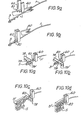
- Figures 9a and 9b are fragmentary, perspective views illustrating successive initial stages in the operation of terminal insertion jaws of the terminal insertion unit; and
- Figures lOa to 10d are fragmentary, perspective views illustrating successive further, and final stages in the operation of the terminal insertion jaws, Figures 10a to lOc also showing terminal positioning arms of the terminal positioning sub-unit in co-operation with the terminal insertion jaws.
- The apparatus to be described is, as illustrated in Figure 1, for inserting
electrical terminals 3 into through cavities 5' in aninsulating housing 5 of a printed circuit board edge connector. Eachterminal 3, which has been connected by crimping to awire 1 or 1', comprises a contact spring 3' which projects laterally from one side of theterminal 3. - As shown in Figure 1, the cavities 5' are arranged in pairs of cavities juxtaposed transversely of the
housing 5, one cavity of each pair 5' being disposed on each side of a printed circuit board receiving channel 5'' of thehousing 5. In order to enable the contact springs 3' of a pair ofterminals 3 inserted into the cavities 5' of a pair, to contact opposite sides of a printed circuit board (not shown) inserted into thechannel 5" , the cavities 5' are such thatterminals 3 can only be inserted into a pair of -cavities 5' with the contact springs 3' Of these terminals facing one another. The apparatus to be described is arranged to take each of a plurality ofterminals 3 supplied to.the apparatus, and to insert it into an individual cavity 5', after rotating the terminal through 90° about the longitudinal axis of itswire 1 to 1', correctly to orient theterminal 3 for insertion into its cavity 5'. The apparatus is accordingly arranged oppositely to rotate theterminals 3 to be inserted into the cavities 5' of each pair, as shown in Figure 1, prior to inserting these terminals into their individual Cavities 5'. - The apparatus will now be described in outline with reference to Figure 2.
- The apparatus comprises a
base plate 100 on which are mounted; ahousing positioning unit 10 for locating eachconnector housing 5 into whichterminals 3 are to be inserted, at a predetermined terminal receiving position; aterminal rotation unit 20 for rotating, as described above, eachterminal 3, which has been conveyed to the apparatus from a crimping station (not shown); and aterminal insertion unit 50 for inserting eachterminal 3 into one of the cavities 5' after the terminal has been rotated through 90° by means of theunit 20. - The
housing positioning unit 10 includes X-Y positioning tables 11 and 12 which are relatively movable at right angles to one another, by means ofelectrical stepping motors housing support plate 13 connected to the table 11, and ahousing holder 14 secured to theplate 13 and in which ahousing 5 can be releasably engaged. In practice, a row ofholders 14 extending longitudinally of the plate 13' is provided. - The terminal rotation unit 20.comprises a slide plate constituting a
carriage 21 which is mounted to slide alonghorizontal guide rods 22 supported bybrackets 8 on thebase plate 100. Thecarriage 21 is provided, on its rear face, with a tapped eye (not shown) through which extends a screw threadedrod 23 which is connected to, and is intermittently rotatable by means of anelectric motor 24 carried by one of thebrackets 8, to move thecarriage 21 along theguide rods 22. Thecarriage 21 is arranged to dwell at a terminal pick-up first position at which it receives, by means described below, awire 1 or 1' to which aterminal 3 has previously been crimped. Thecarriage 21 is then moved to a terminal transfer second dwell position at which the wire, after theterminal 3 has been rotated through 90° on the carriage 21 (by means described below), is seized byterminal insertion jaws 60 of theinsertion unit 50 which insert theterminal 3 into its individual cavity 5' with the aid of terminal grippingarms 78 of aterminal positioning sub-unit 70 of theunit 50, as described below. - The apparatus will now be described in detail.
- As shown in Figures 3 and 4, the
terminal rotation unit 20 comprises a block 25 secured to thecarriage 21 and having formed integrally therewith aguide sector 27 having upper and lower V-sectionarcuate grooves 26 in which rotatably engage three rollers 28 (Figure 3) journalled in ablock 29 which is thereby movable along the sector shaped track defined by thegrooves 26. A terminal rotation member in the form of a swingable, finger-shaped wire clamp 30 described in detail below with reference to Figure 6 and shown only schematically in Figures 2 and 4, is fixed to the side of theblock 29 remote from the block 25. Anendless chain 33 is engaged about two horizontally spacedsprocket wheels 32 rotatably supported by thecarriage 21, and about the sector- shaped under side of achain guide 34 depending from the block 25 as shown in Figure 4.' - The
chain 33 is connected to theblock 29 by means of a bracket 31 (Figure 4) and to aslide block 36 by means of anattachment 35. Theslide block 36 is drivable in reciprocating motion along aguide rod 38 by means of a pneumatic piston-and-cylinder device 37, to rotate thesprocket wheels 32 so as to swing theclamp wire 30 through a predetermined angle about thesector 27. When theslide block 36 is moved from one to another of its end positions, thewire clamp 30 is swung through 90 0. - As shown in Figure 6, the
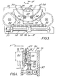
wire clamp 30 includes a main, fixedclamp member 40 arranged to be driven in intermittent reciprocating axial movement in a support block 39, by means of a pneumatic piston-and-cylinder device 41, and a smaller,movable clamp member 42 having a clampingnose 49. Themember 42 is pivotable, by means of a pneumatic piston-and-cylinder device 44, about apin 46, in a clockwise (as seen in Figure 6) sense to clamp a wire when such is received therein in arecess 45 in the free end of themember 40, and in the opposite direction to release the wire from therecess 45. - The terminal insertion unit 50 (shown in detail in Figures 7 and 8) includes an L-shaped support bracket 51 (Figure 2) secured to the
base plate 100, and carrying aframe 52 supporting aslide plate 53. Theplate 53 is connected to the piston rod of a pneumatic piston-and-cylinder device 55 by means of abracket 54. Ahousing 56 slidably connected to theplate 53 contains acranked lever 58 pivoted to across shaft 57 extending between opposed side walls of thehousing 56. One end of thelever 58 is connected to the piston rod 59' of a pneumatic piston-and-cylinder device 59, the other end of thelever 58 being pivotally connected to theterminal insertion jaws 60 which haveterminal stuffing projections 80 at their ends remote from thehousing 56. Thehousing 56 has in its left hand (as seen in Figure 7) wall, anadjustable length stop 61 adapted to limit the rotation of thelever 58 in a clockwise (as seen in Figure 7) sense,-as the piston rod 59' is retracted, so as to limit the descent of thejaws 60 which are mounted for vertical reciprocating movement relative to thehousing 56. - In the vertical position in which they are shown in Figure 7, the
jaws 60 are open as shown in Figure 9a. Further retraction of the piston rod 59' after thelever 58 has engaged thestop 61, causes thehousing 56 to be retracted leftwardly (as seen in Figure 7) to close theinsertion jaws 60 about a wire therebetween to grip it, by virtue of the engagement of thejaws 60 with cam surfaces (not shown) which are fixed relative to theframe 52. - The
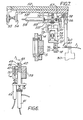
terminal positioning sub-unit 70 is secured to theslide plate 53 by means of a depending plate 53' and extends transversely of theframe 52, as best,seen in Figure 2, being connected to the plate 53' through a slide base 71 (Figure (8). Theslide base 71 carries the cylinder of a piston-and-cylinder device 72 for driving horizontally aslide 73 connected to aslide plate 77 which supports aterminal positioner 75 having a housing 75'. Theslide plate 77 is driven horizontally by a piston-and-cylinder device 74 fixed to theslide 73, in turn horizontally to drive thepositioner 75 between a first position referenced (a) in Figure 8a -and a second position referenced (b) in Figure 8a. - A piston-and-
cylinder device 76 is arranged to open and close theterminal gripping arms 78, through a linkage 78'. Eacharm 78 has, at its end remote from the housing 75', tworecesses 79 and 79' having different configurations, each for receiving aterminal 3 in a different one of the two angular orientations, described above. - The electric motors and the piston-and-cylinder devices mentioned above are automatically operated according to a predetermined programme described below, by means of a conventional pneumatic or electronic control logic system (not shown).
- The operation of the apparatus will now be described in detail.
- The
wires 1 and 1' are intermittently conveyed to theterminal rotation unit 20, one by one, in the direction of the arrow A in Figure 2, by means of pairs of wire clamp jaws 2 (Figure 2) of a conveyor (not shown), from a crimping station (not shown) upstream of the apparatus, at which station, theterminals 3 are crimped to thewires 1. - To receive a
wire 1, thecarriage 21 of theunit 20 is driven to its first position (Figure 5a) to dwell thereat, thewire clamp 30 having been simultaneously displaced by 45° by the device 47 in a clockwise (as seen in Figures 5a and 5b) sense with respect to the centre of theguide sector 27 and being stationary. - When a
wire 1 gripped by a pair ofjaws 2 reaches a position shown in Figure 5a, in which thewire 1 is located centrally of thesector 27, above theunit 20 and opposite to therecess 45 of theclamp 30, themain clamp member 40 is advanced by means of thedevice 41 so that thewire 1 is received in the recess 45 (Figure 5b) whereafter thedevice 44 is actuated to cause themovable clamp member 42 to clamp thewire 1 in therecess 45. - The
jaws 2 are then opened to release thewire 1 and themotor 24 is simultaneously run to slide thecarriage 21 to its second position (Figure 5c). Thedevice 37 is operated simultaneously with the movement of thecarriage 21 to its second position, to move theslide block 36 along theguide rod 38 to cause thechain 33 to rotate thewire clamp 30 in an anticlockwise (as seen in Figures 5a to 5c) sense through 90°, from its Figure 5a and b position to the position shown in Figure 5c, so that theterminal 3 is rotated about the longitudinal axis of thewire 1 and thus about its own longitudinal axis, through 90°, also in an anticlockwise sense. - When the
carriage 21 has reached its second position, themotor 24 and thedevice 37 are stopped. Theterminal insertion jaws 60 of theunit 50 are now moved downwards and leftwards (as seen in Figure 7) by means of thedevice 59, so that thejaws 60 are closed about thewire 1, after thelever 58 has engaged thestop 61, at a position just back from theterminal 3; as shown in Figures 9a and 9b. Thenose 49 of themovable clamp member 42 is now retracted by operation of thedevice 44 to release thewire 1 from therecess 45, themain clamp member 40 is retracted (Figure 5d), and themotor 24 is simultaneously run in a reverse direction to return.thecarriage 21 to its first position, whereby thecarriage 21 is positioned to receive the next wire 1' (Figure 5e), from the next pair ofconveyor jaws 2. Whilst thecarriage 21 is being returned to its first position, thedevice 37 is maintained inoperative so that thewire clamp 30 remains in its fully anticlockwise position, as shown in Figure 5e. Themain clamp member 40 is advanced again to receive the wire 1', themovable clamp member 42 is operated so that the wire 1' is gripped in thewire clamp 30, and thewire clamp 30 is returned to its Figure 5a position whilst thecarriage 21 is being moved to its second position, whereby theterminal 3 on the wire 1' is rotated about its longitudinal axis by 90° in the opposite sense to that in which the terminal on thewire 1 was rotated. The wire 1' is then released from thewire clamp 30 when thejaws 60 have been closed about the wire 1'. - Upon the release of each
wire 1 or 1' from thewire clamp 30, theinsertion jaws 60 co-operate with theterminal positioner 75 to insert theterminal 3 on thewire 1 or I' gripped by thejaws 60 into a corresponding cavity 5' of theconnector housing 5, during the subsequent return movement of thecarriage 21. - When the
insertion jaws 60 have gripped awire 1 or 1', theterminal positioner 75 is driven by thedevice 74 to bring thepositioner 75 into its position (a) or its position (b) in Figure 8a in dependence upon the orientation of theterminal 3. Thedevice 76 is then operated to close thearms 78, so that the crimped portion of theterminal 3 is received in the recesses 79' (Figure lOa) or 79 (Figure lOb), as the case may be of thearms 78. Thedevice 55 is then operated to retract theslide plate 53 leftwardly (as seen in Figure 7) similarly to displace theterminal positioner 75 and theinsertion jaws 60, to insert theterminal 3 into its individual cavity 5' of theconnector housing 5, as shown in Figure 10c. As the leading end of theterminal 3 enters the cavity 5', thedevice 76 is actuated to open thearms 78, and thedevice 2 is operated to move theslide 73 leftwardly (as seen in Figure 8) to retract thearms 78 from between thejaws 60 and thehousing 5, thedevice 55 being still in operation, so that thejaws 60 fully insert theterminal 3 into the cavity 5' with the aid of theterminal stuffing projections 80 on the-jaws 60, as shown in Figure 10d. - Following the terminal insertion operation, the
devices slide plate 53 and theterminal positioner 75, respectively, to their starting positions and the tables 11 and 12 are shifted to position thehousing 5 for the insertion of thenext terminal 3 thereinto, whereby a cycle of operation of the apparatus has been completed.
Claims (10)
1. Apparatus for inserting electrical terminals (3 and 3') connected to a wire (1 or 1'), into respective cavities (5') in an electrical connector housing (5), the apparatus comprising a housing positioning unit (10) arranged to locate the housing (5) in a predetermined terminal receiving position; a terminal insertion unit (50) arranged to insert each terminal (3 and 3') into its respective cavity (5') in the housing (5), when the housing is located in its predetermined position; a terminal rotation member (30) arranged to rotate each terminal (3 or 3') prior to its insertion into its respective cavity (5'), the terminal rotation member (30) being movable towards and away from the terminal insertion unit (50), and means (60) arranged to transfer each rotated terminal from the terminal rotation member (30) to the terminal insertion unit (50), characterised in that the terminal rotation member (30) is arranged to rotate a first terminal (3) in one sense about the longitudinal axis of the wire (1) to which the terminal (3) is connected, in respect of a first traverse of the terminal rotation member (30) towards the terminal insertion unit (50) and to rotate a second terminal (3') in the opposite sense about such axis in respect of a subsequent traverse of the terminal rotation member (30) towards the terminal insertion unit (50), so that the first and second terminals (3 and 3') are inserted into their cavities (5') in oppositely oriented relationship.
2. Apparatus according to Claim 1, characterised in that the terminal rotation member (30) is mounted on a carriage (21) which is movable towards and away from the terminal insertion unit (50), each terminal (3 and 3') being received by the terminal rotation member (30) at the same terminal pick-up position along the path of travel of the carriage (21) and being transferred to the terminal insertion unit (50) at the same terminal transfer position along the path of travel of the carriage (21).
3. Apparatus according to Claim 2, characterised in that the terminal rotation member (30) is mounted on the carriage (21) to swing about the axis of an arcuate guide surface (27) thereon, and is arranged to be swung in one sense about the axis of the guide surface (27) during the first traverse of the carriage (21) and in the opposite sense about such axis during the subsequent traverse of the carriage (21), the terminal rotation member (30) being stationary with respect to such axis during the intermediate return traverse of the carriage (21) away from the terminal insertion unit (30).
4. Apparatus according to Claim 3, characterised in that the terminal rotation member is in the form of an elongate wire clamp (30) one end (40, 49) of which is adapted releasably to receive a wire (l or 1') and the other end of which is arranged to follow the arcuate guide surface which is provided by a guide sector (27) secured to the carriage (21), the wire clamp (30) being mounted on a block (29) which is swingable on bearings (26, 28) about the guide sector (27), the wire clamp (30) being driven through a chain (33) and sprocket (32) mechanism, and the carriage (21) being driven by a separate driving device (24).
5. Apparatus according to any one of the preceding claims, characterised in that the terminal transfer means comprises a pair of terminal insertion jaws (60) of the terminal insertion unit (50), which are movable towards and away from the terminal rotation member (30) transversely of the path of travel thereof, and a movable jaw (49) of the terminal rotation member (30), the terminal insertion jaws (60) being arranged to grasp the wire (1 or 1') to which the,terminal (3 or 3') is connected, at a position just back from the terminal (3 or 3'), the movable jaw (49) being adapted to release the wire (1 or 1') to allow the terminal insertion jaws (60) to carry the wire (1 or 1'), with the terminal (3 or 3') thereon, towards the housing (5), to insert the terminal (3 or 3') into the housing (5) with the aid of wire stuffer projections (80) on the terminal insertion jaws (60).
6. Apparatus according to any one of the preceding claims, characterised in that the terminal insertion unit (50) comprises a terminal positioning sub-unit (70) for accurately locating each terminal (3 or 3') in alignment with the cavity (5') into which it is to be inserted by the terminal insertion unit (50), the terminal positioning sub-unit (70) comprising a pair of terminal positioning arms (78) which are closeable about the terminal (3 or 3') and which are movable between a terminal position location between the terminal insertion jaws (60) and the housing (5), and a retracted position to allow the insertion of the terminal (3 or 3') into its cavity (5).
7. Apparatus according to Claim 6, characterised in that terminal positioning arms (78) are provided with two pairs of recesses (79 and 79') each shaped to receive a terminal (3 or 3') in a different angular position about the longitudinal axis of the wire (1 or 1') to which the terminal is connected, the terminal positioning arms (78) being provided with means (74) for moving them between first and second terminal receiving positions, in dependence upon the angular position of a terminal (3 or 3') grasped by the terminal insertions jaws (60).
8. Apparatus according to Claim 7, characterised in that the terminal positioning sub-unit (70) includes a first driving device (76) for opening and closing the terminal positioning arms (78), a second driving device (74) for moving the terminal positioning arms (78) between their first and second terminal receiving positions and a third driving device {72) for moving the terminal positioning arms (78) between their terminal receiving location and their retracted position.
9. Apparatus according to Claim 8, characterised in that the terminal insertion jaws (60) are secured to a first slide (53) which is in turn mounted to a frame (52) fixedly connected to a base plate (100) of the apparatus, the first slide (53) being slidable with respect to a slide base (71) carrying the positioning sub-unit (70), the third driving device (72) being mounted on the slide base (71) and the first and second driving devices (74 and 76) being carried by second and third slides (73 and 77) which are slidable with respect to the slide base (71), and with respect to one another, the first slide (53) being slidable transversely of the path of traverse of the terminal rotation member (30) and the second and third slides (73 and 77) being slidable in a direction parallel to such path.
10. A method of inserting elongate electrical terminals (3 and 3') into respective cavities (5') in an electrical connector housing (5), comprising the steps of supplying respective terminals (3) to terminal rotation means (30) at a terminal receiving position thereof, operating the terminal rotation means (30) to rotate each terminal (3), in the course of moving the terminal rotation means (30) from its terminal receiving position, towards the housing (5) and transferring each terminal (3) from the terminal rotation means (30) into a respective cavity (5) of the housing (5); characterised in that a first terminal (3) is rotated by the terminal rotation means (30) by 90° about the longitudinal axis of the first terminal (3), in a first sense, and is transferred into the cavity (5') whilst returning the terminal rotation means (30) to its terminal receiving position; and a second terminal (3') is then supplied to the terminal rotating means (30), which is operated to rotate the second terminal (3') through 900 about its longitudinal axis in a second sense opposite to the first sense, whilst moving the terminal rotating means (30) towards the housing (5), the second terminal (3') is then transferred from the terminal rotating means (30) into a second cavity (5') in the housing (5), whereby the second terminal (3') is oppositely angularly positioned in the housing (5) with respect to the first terminal (3).
Applications Claiming Priority (2)
| Application Number | Priority Date | Filing Date | Title |
|---|---|---|---|
| GB8018044 | 1980-06-03 | ||
| GB8018044 | 1980-06-03 |
Publications (1)
| Publication Number | Publication Date |
|---|---|
| EP0041332A2 true EP0041332A2 (en) | 1981-12-09 |
Family
ID=10513775
Family Applications (1)
| Application Number | Title | Priority Date | Filing Date |
|---|---|---|---|
| EP19810302186 Withdrawn EP0041332A2 (en) | 1980-06-03 | 1981-05-18 | Apparatus for, and a method of, inserting electrical terminals into an electrical connector housing |
Country Status (3)
| Country | Link |
|---|---|
| EP (1) | EP0041332A2 (en) |
| JP (1) | JPS5723488A (en) |
| ES (1) | ES8204241A1 (en) |
Cited By (12)
| Publication number | Priority date | Publication date | Assignee | Title |
|---|---|---|---|---|
| US4470181A (en) * | 1981-04-27 | 1984-09-11 | Amp Incorporated | Apparatus for loading color-coded wires into a connector half |
| DE3727429A1 (en) * | 1986-09-16 | 1988-03-17 | Amp Inc | Connection rotation station |
| EP0286208A1 (en) * | 1987-04-07 | 1988-10-12 | The Whitaker Corporation | Electrical lead parking and sorting station |
| EP0286207A1 (en) * | 1987-04-07 | 1988-10-12 | The Whitaker Corporation | Electrical harness making apparatus |
| EP0286206A1 (en) * | 1987-04-07 | 1988-10-12 | The Whitaker Corporation | Electrical-terminal block loading apparatus |
| EP0330309A2 (en) * | 1988-02-23 | 1989-08-30 | Molex Incorporated | Crimped wire harness fabricator and method |
| EP0348615A1 (en) * | 1988-07-01 | 1990-01-03 | Komax Ag | Process for automatically mounting electrical conductors with contact elements in connector shells |
| WO1991015042A1 (en) * | 1990-03-28 | 1991-10-03 | Siemens Aktiengesellschaft | Process for the manufacture of connectors |
| EP0534822A1 (en) * | 1991-09-26 | 1993-03-31 | AEROSPATIALE Société Nationale Industrielle | Device and machine for inserting connection elements into connectors |
| EP0817333A2 (en) * | 1996-06-25 | 1998-01-07 | Sumitomo Wiring Systems, Ltd. | A wire assembly producing method and a terminal connected wire inserting apparatus |
| GB2328323A (en) * | 1997-08-15 | 1999-02-17 | Japan Aviation Electron | Mounting a connector to a board by rotation of the connector and using a clip |
| CN114833589A (en) * | 2022-04-26 | 2022-08-02 | 东莞市品晔电子有限公司 | Connector terminal edging milling flutes necking machine |
-
1981
- 1981-05-18 EP EP19810302186 patent/EP0041332A2/en not_active Withdrawn
- 1981-06-02 ES ES502697A patent/ES8204241A1/en not_active Expired
- 1981-06-02 JP JP8391681A patent/JPS5723488A/en active Pending
Cited By (21)
| Publication number | Priority date | Publication date | Assignee | Title |
|---|---|---|---|---|
| US4470181A (en) * | 1981-04-27 | 1984-09-11 | Amp Incorporated | Apparatus for loading color-coded wires into a connector half |
| DE3727429B4 (en) * | 1986-09-16 | 2004-05-06 | Amp Inc. | Port rotation station |
| DE3727429A1 (en) * | 1986-09-16 | 1988-03-17 | Amp Inc | Connection rotation station |
| EP0286208A1 (en) * | 1987-04-07 | 1988-10-12 | The Whitaker Corporation | Electrical lead parking and sorting station |
| EP0286207A1 (en) * | 1987-04-07 | 1988-10-12 | The Whitaker Corporation | Electrical harness making apparatus |
| EP0286206A1 (en) * | 1987-04-07 | 1988-10-12 | The Whitaker Corporation | Electrical-terminal block loading apparatus |
| US4835844A (en) * | 1987-04-07 | 1989-06-06 | Amp Incorporated | Block loading apparatus |
| US4925007A (en) * | 1987-04-07 | 1990-05-15 | Amp Incorporated | Electrical lead parking and sorting station |
| EP0330309A2 (en) * | 1988-02-23 | 1989-08-30 | Molex Incorporated | Crimped wire harness fabricator and method |
| EP0330309A3 (en) * | 1988-02-23 | 1991-03-27 | Molex Incorporated | Crimped wire harness fabricator and method |
| EP0348615A1 (en) * | 1988-07-01 | 1990-01-03 | Komax Ag | Process for automatically mounting electrical conductors with contact elements in connector shells |
| WO1991015042A1 (en) * | 1990-03-28 | 1991-10-03 | Siemens Aktiengesellschaft | Process for the manufacture of connectors |
| FR2681987A1 (en) * | 1991-09-26 | 1993-04-02 | Aerospatiale | DEVICE AND MACHINE FOR CONNECTING CONNECTION ELEMENTS INTO CONNECTORS. |
| US5333374A (en) * | 1991-09-26 | 1994-08-02 | Societe Nationale Industrielle Et Aerospatiale | Device for connecting connexion elements into connectors |
| US5485660A (en) * | 1991-09-26 | 1996-01-23 | Aerospatiale Societe Nationale Industrielle | Machine for connection connexion elements into connectors |
| EP0534822A1 (en) * | 1991-09-26 | 1993-03-31 | AEROSPATIALE Société Nationale Industrielle | Device and machine for inserting connection elements into connectors |
| EP0817333A2 (en) * | 1996-06-25 | 1998-01-07 | Sumitomo Wiring Systems, Ltd. | A wire assembly producing method and a terminal connected wire inserting apparatus |
| EP0817333A3 (en) * | 1996-06-25 | 1999-01-13 | Sumitomo Wiring Systems, Ltd. | A wire assembly producing method and a terminal connected wire inserting apparatus |
| GB2328323A (en) * | 1997-08-15 | 1999-02-17 | Japan Aviation Electron | Mounting a connector to a board by rotation of the connector and using a clip |
| GB2328323B (en) * | 1997-08-15 | 2002-03-13 | Japan Aviation Electron | Mounting apparatus and method for mounting a connector to a board with a turn of the connector |
| CN114833589A (en) * | 2022-04-26 | 2022-08-02 | 东莞市品晔电子有限公司 | Connector terminal edging milling flutes necking machine |
Also Published As
| Publication number | Publication date |
|---|---|
| ES502697A0 (en) | 1982-04-01 |
| JPS5723488A (en) | 1982-02-06 |
| ES8204241A1 (en) | 1982-04-01 |
Similar Documents
| Publication | Publication Date | Title |
|---|---|---|
| US3872584A (en) | Method and apparatus for processing a plurality of wire leads | |
| US4194281A (en) | Apparatus and method for stripping wire leads | |
| EP0041332A2 (en) | Apparatus for, and a method of, inserting electrical terminals into an electrical connector housing | |
| CA1049236A (en) | Arranging randomly positioned articles into preselected positions | |
| US6135164A (en) | Apparatus and method for preparing wires in a harness making machine | |
| EP0127330B1 (en) | Modular lead maker | |
| EP0286206B1 (en) | Electrical-terminal block loading apparatus | |
| US4196510A (en) | Apparatus and method for production of wire leads | |
| US3869781A (en) | Apparatus for attaching terminals to electric conductors | |
| US4825537A (en) | Automated crimped wire harness fabricator | |
| US6279215B1 (en) | Automatic wire cutting and terminating apparatus | |
| EP0040491A1 (en) | Apparatus for inserting electrical terminals into an electrical connector housing | |
| US4409734A (en) | Harness making apparatus and method | |
| EP0190821A2 (en) | Apparatus for connecting electrical connectors to cable | |
| US4395818A (en) | Block loader | |
| WO1989007850A1 (en) | Apparatus for inserting terminals on the ends of wires into cavities in an electrical connector | |
| EP0131436B1 (en) | Stripping apparatus for stripping coated wire | |
| JP3703503B2 (en) | Cable bundling device for cable processing machine | |
| US5761796A (en) | Device for fitting out connector shells | |
| CN111585139A (en) | Wire harness processing device, wire harness bending device and wire harness processing system | |
| EP0286207B1 (en) | Electrical harness making apparatus | |
| EP0660466A2 (en) | Terminal inserting drive apparatus for inserting terminals on wire | |
| EP0817329A1 (en) | Apparatus for making wire harnesses | |
| EP0765535B1 (en) | A machine and method for producing electrical harnesses | |
| US4633570A (en) | Apparatus for assembling an electrical connector to a cable |
Legal Events
| Date | Code | Title | Description |
|---|---|---|---|
| PUAI | Public reference made under article 153(3) epc to a published international application that has entered the european phase |
Free format text: ORIGINAL CODE: 0009012 |
|
| AK | Designated contracting states |
Designated state(s): AT BE CH DE FR GB IT NL SE |
|
| STAA | Information on the status of an ep patent application or granted ep patent |
Free format text: STATUS: THE APPLICATION HAS BEEN WITHDRAWN |
|
| 18W | Application withdrawn |
Withdrawal date: 19820525 |
|
| RIN1 | Information on inventor provided before grant (corrected) |
Inventor name: TOMINOI, KUNITADA |