EP0040734B1 - Arrangement for the cooling of a superconducting excitation winding and of a damping shield of the rotor of an electric machine - Google Patents
Arrangement for the cooling of a superconducting excitation winding and of a damping shield of the rotor of an electric machine Download PDFInfo
- Publication number
- EP0040734B1 EP0040734B1 EP81103525A EP81103525A EP0040734B1 EP 0040734 B1 EP0040734 B1 EP 0040734B1 EP 81103525 A EP81103525 A EP 81103525A EP 81103525 A EP81103525 A EP 81103525A EP 0040734 B1 EP0040734 B1 EP 0040734B1
- Authority
- EP
- European Patent Office
- Prior art keywords
- coolant
- line
- cooling
- chamber
- rotor
- Prior art date
- Legal status (The legal status is an assumption and is not a legal conclusion. Google has not performed a legal analysis and makes no representation as to the accuracy of the status listed.)
- Expired
Links
Images
Classifications
-
- H—ELECTRICITY
- H02—GENERATION; CONVERSION OR DISTRIBUTION OF ELECTRIC POWER
- H02K—DYNAMO-ELECTRIC MACHINES
- H02K55/00—Dynamo-electric machines having windings operating at cryogenic temperatures
- H02K55/02—Dynamo-electric machines having windings operating at cryogenic temperatures of the synchronous type
- H02K55/04—Dynamo-electric machines having windings operating at cryogenic temperatures of the synchronous type with rotating field windings
-
- H—ELECTRICITY
- H02—GENERATION; CONVERSION OR DISTRIBUTION OF ELECTRIC POWER
- H02K—DYNAMO-ELECTRIC MACHINES
- H02K9/00—Arrangements for cooling or ventilating
- H02K9/22—Arrangements for cooling or ventilating by solid heat conducting material embedded in, or arranged in contact with, the stator or rotor, e.g. heat bridges
- H02K9/225—Heat pipes
-
- Y—GENERAL TAGGING OF NEW TECHNOLOGICAL DEVELOPMENTS; GENERAL TAGGING OF CROSS-SECTIONAL TECHNOLOGIES SPANNING OVER SEVERAL SECTIONS OF THE IPC; TECHNICAL SUBJECTS COVERED BY FORMER USPC CROSS-REFERENCE ART COLLECTIONS [XRACs] AND DIGESTS
- Y02—TECHNOLOGIES OR APPLICATIONS FOR MITIGATION OR ADAPTATION AGAINST CLIMATE CHANGE
- Y02E—REDUCTION OF GREENHOUSE GAS [GHG] EMISSIONS, RELATED TO ENERGY GENERATION, TRANSMISSION OR DISTRIBUTION
- Y02E40/00—Technologies for an efficient electrical power generation, transmission or distribution
- Y02E40/60—Superconducting electric elements or equipment; Power systems integrating superconducting elements or equipment
-
- Y—GENERAL TAGGING OF NEW TECHNOLOGICAL DEVELOPMENTS; GENERAL TAGGING OF CROSS-SECTIONAL TECHNOLOGIES SPANNING OVER SEVERAL SECTIONS OF THE IPC; TECHNICAL SUBJECTS COVERED BY FORMER USPC CROSS-REFERENCE ART COLLECTIONS [XRACs] AND DIGESTS
- Y10—TECHNICAL SUBJECTS COVERED BY FORMER USPC
- Y10S—TECHNICAL SUBJECTS COVERED BY FORMER USPC CROSS-REFERENCE ART COLLECTIONS [XRACs] AND DIGESTS
- Y10S505/00—Superconductor technology: apparatus, material, process
- Y10S505/825—Apparatus per se, device per se, or process of making or operating same
- Y10S505/876—Electrical generator or motor structure
- Y10S505/877—Rotary dynamoelectric type
- Y10S505/878—Rotary dynamoelectric type with cooling
Definitions
- the invention relates to a device for cooling a superconducting field winding in the rotor of an electrical machine, in particular a turbogenerator, with at least one coolant chamber, which in the operating state has a vaporous and a liquid phase of a co-rotating feed line connected to the coolant chamber at a connection head contains cryogenic coolant introduced with subcritical pressure, with coolant paths running through the excitation winding, which are connected to the liquid space of the coolant space occupied by the liquid phase, with at least one coolant discharge line, which is connected to the vapor space of the coolant space occupied by the gaseous phase, and with at least one coolant storage chamber containing liquid coolant and with at least one further, coolant path running in a loop, which has a damper shield arranged around the excitation winding thermally connected and which is connected at its beginning and end to the coolant storage chamber.
- the superconducting excitation winding of a generator must be kept at such a low temperature during the operation of the machine that its superconductors do not change into the normal conducting state.
- cooling of the winding with liquid helium as cryogenic coolant is therefore provided, the heat loss generated in the superconductors and the heat introduced from the outside via torque-transmitting parts of the rotor body leading to a partial evaporation of the coolant.
- the heat flow introduced into the low-temperature area of the rotor can, however, be greatly reduced according to the principle of countercurrent cooling if the evaporated but still cool coolant exhaust gas is guided in good thermal contact along the torque-transmitting rotor parts, absorbs a large part of the incoming heat, heats up and leaves the rotor at a connection head as warm gas.
- the excitation winding can be surrounded by one or more damper shields which shield the magnetic field and at the same time dampen oscillations. Damper shields made of thermally and electrically highly conductive material are favorable for shielding low-frequency fields.
- the damper shield of the machine known from the EPRI report is fastened to a support cylinder of the rotor body, in which individual channels are present which serve as damper cooling channels.
- liquid helium is provided, which flows in these channels due to a so-called thermosiphon effect: heat generated in the cold damper shield penetrates the support cylinder, reaches the helium located in its cooling ducts, and starts convection there. Due to this convection, the heated helium flows back into a helium bath in the center of the rotor, where a corresponding amount of liquid helium evaporates.
- a coolant circuit is formed due to a thermosiphon effect from the helium bath in the coolant storage chamber through the first damper shield to the phase separator and through the second damper shield back to the helium bath.
- the heat supply creates helium vapor in the helium bath of the coolant storage chamber and in the phase separator, which can escape through special gas outlet openings and also through an emergency exit provided in the separator.
- a reflux valve in the connection between the coolant supply chamber and the coolant chamber containing the coolant bath for the winding prevents the pressure increase in the coolant supply chamber from having an effect on the coolant bath of the winding. This valve also enables the coolant supply chamber to be filled with liquid helium.
- the object of the present invention is therefore to simplify the cooling device of the type mentioned at the outset and to improve it in such a way that the removal of coolant vapor caused by losses in the damper shield is facilitated from the rotor without any significant heating of the cooling element for the Excitation winding to be provided liquid coolant is connected.
- the coolant supply chamber is connected directly to the coolant supply line via a radially extending connecting line and that for a discharge of gaseous coolant fractions from the coolant supply chamber to the connecting head, the flow cross section of the radially extending connecting line and the flow cross section at least that between the connecting head and the connection point of the radial connecting line extending portion of the coolant supply line are sized accordingly.
- the coolant path of the damper shield comprises at least a pair of parallel, essentially axially extending coolant lines which are connected to one another at the point furthest away from the assigned coolant storage chamber.
- One coolant line of each line pair is advantageously located radially further outward, while the other coolant line is arranged radially further inward. In this way, a very effective coolant flow through the coolant lines is due to a Thermosiphon effect enables.
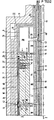
- the guidance of a coolant is indicated only by a part of the rotor of an electrical machine, in particular a turbogenerator, adjoining a connection head.
- the rotor parts which are not detailed in the figure, can correspond, for example, to parts of a machine which is known from DE-OS 2 439 719. From the figure, only a part of the upper half of the rotor with a cooling device according to the invention can be seen.
- a rotor body 3 of the machine which is rotatably mounted about an axis 2, contains a winding support 4 which is provided with slots 5, into which the conductors of a superconducting excitation winding 6 are introduced.
- the conductors of the winding 6 contain superconducting material; Liquid helium is provided as the cryogenic coolant.
- the rotor parts 10 and 11 are generally at about room temperature.
- the required for cooling helium is at subcritical pressure, ie for example in normalsiedenden state at normal pressure or a slight overpressure of for example 1.1 to 10 5 Pa and removed at a temperature of about 4.4 K of a coolant supply means not shown in the figure and introduced into the rotor via a helium coupling on a connection head which is not described in more detail.
- a helium coupling which is known, for example, from the publication "Siemens Research and Development Reports", Volume 5 (1976), No. 1, page 13, the coolant is thereby transferred from stationary to rotating machine parts. The coolant thus flows into a co-rotating feed line 13 which extends in the interior of the rotor body in the axial direction.
- This feed line is a double tube concentric to axis 2 with a coolant guide space which is annular in cross section.
- it can, for example, also consist of several individual tubes that lie together on the jacket of a cylinder, or it can be a simple, centrally arranged tube if no other lines are required in the center.
- a liquid fraction of the coolant designated A is stored in the feed line 13 under the action of the centrifugal force in a radially outer region 14 and a gaseous fraction B in the region facing the rotor axis 2 15 of the supply line 13.
- the liquid helium required for cooling the excitation winding 6 is taken from the area 14 of the feed line 13 containing the liquid portion A, for example approximately in the middle of the rotor indicated by a dashed line 16, and via a coolant feed line 17 initially into a coolant chamber 18 arranged concentrically around the feed line 13 transferred.
- a circuit is advantageously provided in which the known self-pumping effect is used.
- a corresponding cooling circuit is e.g. B. provided in the cooling device known from DE-OS 2 830 887.
- the coolant vapor B 1 present in the coolant chamber 18 is discharged to the outside via a specially designed exhaust pipe 22.
- a self-pumping effect is used to extract the gaseous coolant.
- the coolant gas withdrawn at a point near the axis of the steam chamber 19 via a radially extending pipe 23 is namely warmed up by being used for countercurrent cooling of a torque-transmitting connecting piece 24 of the rotor body 3.
- This connecting piece 24 is the front end piece of a hollow cylindrical carrier body part 25 of the rotor body 3 and extends between a cold middle part 26 of this carrier body part and the warm side part 11 of the rotor body.
- the exhaust gas line 22 also contains an axially extending line part 28, which is thermally connected to the connector 24 remote from the axis and which acts as a heat exchanger.
- the so heated and designated B 2 coolant exhaust gas is then returned near the axis and at the connection head not shown in the figure from the Runners rejected and fed to a chiller. Because of the self-pumping effect for pumping out the coolant exhaust gas, a negative pressure is then advantageously established in the exhaust pipe 23 and thus in the coolant chamber 18, which, for. B. is below 10 5 Pa.
- the coolant in the supply line 13 is under normal pressure or a slight excess pressure, but there is a negative pressure in the coolant chamber 18, a pressure equalization must take place between these two rooms.
- the pressure compensation is achieved in a known manner due to the special design of the coolant feed line 17 as a pressure compensation line (cf., for example, »Cryogenics «, 1977, pages 429 to 433).
- the coolant feed line 17 contains a tubular line part 30, which is connected to the supply line 13 and leads radially outwards, to the outer end of which a tubular line part 31 leading radially inwards and opening into the coolant chamber 18 is connected.
- connection point 32 there is pressure equilibrium at the connection point 32 remote from the axis between the tubular line parts 30 and 31, since the two helium columns in these line parts have different temperatures and therefore densities due to different pressures.
- Lowering the level in the coolant chamber 18 to a larger radius also causes a pressure imbalance at the connection point 32.
- Helium can then continue to flow in via the feed line 17 until the equilibrium condition between the pressures is restored.
- the field winding is surrounded by two co-rotating damper shields 34 and 35.
- the damper shield 34 is attached to the outside of the hollow cylindrical outer part 10 of the rotor body 3 and is at room temperature, while the damper shield 35 is arranged on the inside of the hollow cylindrical carrier body part 25 and is cooled to low temperature.
- this plate 35 which is advantageously made of a material with very good thermal and electrical conductivity such. B. copper, there is practically no heat loss in stationary generator operation. It is only during the relatively short transient operating cases that a very large amount of heat is temporarily released.
- the cooling system required for cooling the inner damper shield 35 is advantageously largely separate from the system for cooling the field winding 6.
- This damper cooling system contains one or more pairs of axially running damper cooling channels 36 and 37, at least one coolant storage chamber 38 and at least one radially running, tubular connecting line 39
- the coolant storage chamber 38 is connected to the helium supply line 13 and thus to the cooling system of the excitation winding 6 only via this connecting line.
- Each pair of damper cooling ducts 36 and 37 is connected to the coolant storage chamber 38 via two connecting lines 40 and 41, the connecting line 40 opening radially further out and the connecting line 41 radially further inside into the chamber 38.
- the two cooling channels of a pair of cooling channels are also advantageously not arranged at the same distance with respect to the rotor axis 2, but rather the damper cooling channel 36 lies on a larger radius with respect to the axis 2 than the cooling channel 37.
- the two cooling channels 36 and 37 of a pair of cooling channels are also connected to one another at a point 42 which is the most distant from the coolant storage chamber 38 assigned to them.
- this connection point is located in the middle of the rotor indicated by the dashed line 16, since it is assumed that a corresponding cooling circuit for the cold damper shield is also provided on the rotor part which is not shown in the figure. This enables the coolant provided for cooling the damper shield 35 to flow in a closed circuit.
- Each pair of cooling channels forms a thermosiphon loop together with the connecting lines 40 and 41.
- the helium in the cooling channels 36 and 37 and the connecting lines 40 and 41 experiences a lift towards the rotor axis 2.
- the heated helium strives towards the rotor axis 2 and reaches the helium supply line 13 via the radial connecting line 39 at a connection point 43.
- a part of the helium evaporates here and leaves the rotor in the gas space 15 of this supply line near the axis.
- the damping of the winding is impaired Freezing largely excluded. Since the axial helium feed line 13 is dimensioned sufficiently large, a sudden amount of helium vapor can escape through the rotor through its gas space 15 without a large increase in pressure. A slight increase in pressure in the axial feed line 13 has at most the consequence that the relatively small amount of liquid helium A located in the feed line is pumped into the coolant chamber 18 via the feed line 17.
- the pressure of the deflection point 32 mainly depends on the radial distance of the helium mirror in the coolant chamber 18 with respect to the axis of rotation 2 and on the distance of the deflection point 32 from the axis of rotation 2. If this is, for example, 0.4 m and is large compared to the radial distance of the helium level in the coolant chamber 18, this pressure is approximately 11-10 5 Pa at a rotor speed of 50 revolutions per second.
- the rotor body 3 indicated in the figure also contains a hollow cylindrical component 46 acting as a radiation shield, which is located between the outer part 10 of the rotor body 3 and its hollow cylindrical carrier body part 25 surrounding the cold damper shield 35.
- This radiation shield 46 is mechanically and thermally connected on its end faces to the torque-transmitting connecting parts 24 of the carrier body part 25.
- the figure also shows a coolant exhaust gas line 48 close to the axis, via which the exhaust gas is led out of the rotor, which serves for countercurrent cooling of the turbine-side end piece of the torque-transmitting hollow cylindrical rotor body part 25, which is not shown in the figure.
Description
Die Erfindung bezieht sich auf eine Einrichtung zur Kühlung einer supraleitenden Erregerwicklung im Läufer einer elektrischen Maschine, insbesondere eines Turbogenerators, mit mindestens einem Kühlmittelraum, der im Betriebszustand eine dampfförmige und eine flüssige Phase eines an einem Anschlußkopf in mindestens eine mit dem Kühlmittelraum verbundene, mitrotierende Zuführungsleitung mit unterkritischem Druck eingeleiteten kryogenen Kühlmittels enthält, mit durch die Erregerwicklung verlaufenden Kühlmittelwegen, die mit dem von der flüssigen Phase eingenommenen Flüssigkeitsraum des Kühlmittelraumes verbunden sind, mit mindestens einer Kühlmittelabführungsleitung, die an den von der gasförmigen Phase eingenommenen Dampfraum des Kühlmittelraumes angeschlossen ist, und mit mindestens einer flüssiges Kühlmittel enthaltenden Kühlmittelvorratskammer sowie mit mindestens einem weiteren, schleifenartig verlaufenden Kühlmittelweg, der mit einem um die Erregerwicklung angeordneten Dämpferschild thermisch verbunden und der an seinem Anfang und Ende an die Kühlmittelvorratskammer angeschlossen ist. Eine derartige Kühleinrichtung ist aus dem Bericht von M. T. Brown et al. mit dem Titel »Rotor Cooling System for a 10 MVA Superconducting Generator« aus: Proceedings of the 1979 Cryogenic Engineering Conference, Madison (Wisconsin), USA, 21.-24. 8. 1979, Paper IC 9, bekannt.The invention relates to a device for cooling a superconducting field winding in the rotor of an electrical machine, in particular a turbogenerator, with at least one coolant chamber, which in the operating state has a vaporous and a liquid phase of a co-rotating feed line connected to the coolant chamber at a connection head contains cryogenic coolant introduced with subcritical pressure, with coolant paths running through the excitation winding, which are connected to the liquid space of the coolant space occupied by the liquid phase, with at least one coolant discharge line, which is connected to the vapor space of the coolant space occupied by the gaseous phase, and with at least one coolant storage chamber containing liquid coolant and with at least one further, coolant path running in a loop, which has a damper shield arranged around the excitation winding thermally connected and which is connected at its beginning and end to the coolant storage chamber. Such a cooling device is known from the report by M. T. Brown et al. entitled "Rotor Cooling System for a 10 MVA Superconducting Generator" from: Proceedings of the 1979 Cryogenic Engineering Conference, Madison (Wisconsin), USA, 21-24. 8. 1979, Paper IC 9, known.
Die supraleitende Erregerwicklung eines Generators muß während des Betriebs der Maschine auf so tiefer Temperatur gehalten werden, daß ihre Supraleiter nicht in den normalleitenden Zustand übergehen. Im allgemeinen ist deshalb eine Kühlung der Wicklung mit flüssigem Helium als kryogenem Kühlmittel vorgesehen, wobei die in den Supraleitern entstehende Verlustwärme und die von außen über drehmomentübertragende Teile des Läuferkörpers eingeleitete Wärme zu einem teilweisen Verdampfen des Kühlmittels führen. Der in den Tieftemperaturbereich des Läufers eingeleitete Wärmestrom kann jedoch nach dem Prinzip einer Gegenstromkühlung stark vermindert werden, wenn das verdampfte, aber noch kalte Kühlmittelabgas in gutem Wärmekontakt an den drehmomentübertragenden Läuferteilen entlanggeführt wird, dort einen großen Teil der einströmenden Wärme aufnimmt, sich dabei erwärmt und als warmes Gas den Läufer an einem Anschlußkopf verläßt.The superconducting excitation winding of a generator must be kept at such a low temperature during the operation of the machine that its superconductors do not change into the normal conducting state. In general, cooling of the winding with liquid helium as cryogenic coolant is therefore provided, the heat loss generated in the superconductors and the heat introduced from the outside via torque-transmitting parts of the rotor body leading to a partial evaporation of the coolant. The heat flow introduced into the low-temperature area of the rotor can, however, be greatly reduced according to the principle of countercurrent cooling if the evaporated but still cool coolant exhaust gas is guided in good thermal contact along the torque-transmitting rotor parts, absorbs a large part of the incoming heat, heats up and leaves the rotor at a connection head as warm gas.
In der supraleitenden Erregerwicklung selbst entsteht unter anderem Verlustwärme, wenn die Supraleiter einem magnetischen Wechselfeld ausgesetzt werden. Im Läufer eines Generators tritt dies z. B. dann auf, wenn bei Schieflast nicht alle Stromphasen der Ständerwicklung gleichmäßig belastet sind, ferner nach einer Kurzschlußfortschaltung oder bei Pendelungen, bei denen die Läuferdrehzahl vorübergehend mit der vorbestimmten Netzfrequenz nicht völlig übereinstimmt. Um in solchen transienten Betriebszuständen die Wechselfeldamplituden an den Supraleitern kleinzuhalten, kann die Erregerwicklung von einem oder mehreren Dämpferschilden umgeben werden, die das Magnetfeld abschirmen und gleichzeitig Pendelungen dämpfen. Zur Abschirmung von niederfrequenten Feldern sind auf tiefer Temperatur gehaltene Dämpferschilde aus thermisch und elektrisch gut leitendem Material günstig. In einem Dämpferschild entsteht nämlich beim stationären Generatorbetrieb praktisch keine Verlustwärme. Nur während der verhältnismäßig kurzen transienten Betriebsfälle, insbesondere bei Pendelungen, wird vorübergehend eine sehr große Verlustwärme frei. Dabei darf, im Gegensatz zu den Supraleitern der Erregerwicklung, deren Temperatur auch während der transienten Betriebsfälle unter der Sprungtemperatur ihres supraleitenden Materials bleiben muß, die Temperatur des kalten Dämpferschildes stärker anwachsen, beispielsweise auf 20 bis 30 Kelvin.In the superconducting field winding itself, heat is generated when the superconductors are exposed to an alternating magnetic field. In the rotor of a generator, this occurs e.g. B. on when unbalanced load all current phases of the stator winding are evenly loaded, further after a short-circuit advancement or in oscillations in which the rotor speed temporarily does not completely match the predetermined network frequency. In order to keep the alternating field amplitudes at the superconductors small in such transient operating states, the excitation winding can be surrounded by one or more damper shields which shield the magnetic field and at the same time dampen oscillations. Damper shields made of thermally and electrically highly conductive material are favorable for shielding low-frequency fields. There is practically no heat loss in a damper shield during stationary generator operation. A very large heat loss is only temporarily released during the relatively short transient operating cases, especially in the case of commuting. In contrast to the superconductors of the field winding, whose temperature must remain below the transition temperature of their superconducting material even during transient operating cases, the temperature of the cold damper shield may increase more, for example to 20 to 30 Kelvin.
Ein Turbogenerator mit einer von einem solchen Dämpferschild umgebenden supraleitenden Erregerwicklung ist aus dem Bericht des Electric Power Research Institute, USA: »EPRI EL-577, Project 429-1, Final Report«, November 1977, Seiten 3-258 bis 3-270 bekannt. Bei der Kühlung der Erregerwicklung wird ein sogenannter Selbstpump-Effekt ausgenutzt, wie er z. B. beschrieben ist in der Dissertation von A. Bejan: »Improved thermal Design of the Cryogenic Cooling System for a Superconducting Synchronous Generator«, Ph. D.-Thesis, Massachusetts Institute of Technology (USA), Dezember 1974, Seiten 148 bis 159. Der Dämpferschild der aus dem EPRI-Bericht bekannten Maschine ist auf einem Tragzylinder des Läuferkörpers befestigt, in dem einzelne Kanäle vorhanden sind, welche als Dämpferkühlkanäle dienen. Zu dieser indirekten Kühlung des Dämpferschildes ist flüssiges Helium vorgesehen, das in diesen Kanälen aufgrund einer sogenannten Thermosiphonwirkung strömt: In dem kalten Dämpferschild erzeugte Wärme durchdringt den Tragzylinder, gelangt in das in seinen Kühlkanälen befindliche Helium und facht dort eine Konvektion an. Aufgrund dieser Konvektion fließt das erwärmte Helium in ein im Zentrum des Läufers vorhandenes Heliumbad zurück, wo eine entsprechende Menge an flüssigem Helium verdampft.A turbogenerator with a superconducting excitation winding surrounded by such a damper shield is known from the report of the Electric Power Research Institute, USA: "EPRI EL-577, Project 429-1, Final Report", November 1977, pages 3-258 to 3-270 . In the cooling of the excitation winding, a so-called self-pumping effect is used, as z. B. is described in the dissertation by A. Bejan: "Improved thermal Design of the Cryogenic Cooling System for a Superconducting Synchronous Generator", Ph. D. Thesis, Massachusetts Institute of Technology (USA), December 1974, pages 148 to 159 The damper shield of the machine known from the EPRI report is fastened to a support cylinder of the rotor body, in which individual channels are present which serve as damper cooling channels. For this indirect cooling of the damper shield, liquid helium is provided, which flows in these channels due to a so-called thermosiphon effect: heat generated in the cold damper shield penetrates the support cylinder, reaches the helium located in its cooling ducts, and starts convection there. Due to this convection, the heated helium flows back into a helium bath in the center of the rotor, where a corresponding amount of liquid helium evaporates.
Bei dieser bekannten Kühleinrichtung ist gewährleistet, daß die Wärme aus dem kalten Dämpferschild nicht direkt in den Bereich der supraleitenden Erregerwicklung gelangt, da die Dämpferkühlkanäle von den Wicklungskühlkanälen thermisch isoliert sind. Außerdem ermöglicht ein guter Wärmeübergang von dem Tragzylinder in das in seinen Kühlkanälen befindliche Helium eine rasche Dämpferkühlung. Bei dieser Kühleinrichtung ist jedoch eine Abführung des entstehenden gasförmigen Heliums durch Abgasleitungen mit verhältnismäßig kleinem Strömungsquerschnitt vorgesehen, die an den drehmomentübertragenden Teilen des Läuferkörpers verlaufen. Ein in einem Störungsfall plötzlich auftretender großer Heliumdampfstrom kann dann aber den Läufer durch diese Abgasleitungen nicht schnell genug verlassen, so daß der Druck in dem zentralen Heliumbad entsprechend ansteigt. Die Folge davon ist auch ein Ansteigen der Sättigungstemperatur des zur Kühlung der supraleitenden Erregerwicklung verwendeten Heliums dieses Bades und damit der Temperatur der Wicklung selbst.In this known cooling device it is ensured that the heat from the cold damper shield does not reach the area of the superconducting field winding, since the damper cooling ducts are thermally insulated from the winding cooling ducts. In addition, good heat transfer from the support cylinder into the helium located in its cooling channels enables rapid damper cooling lung. In this cooling device, however, the resulting gaseous helium is discharged through exhaust pipes with a relatively small flow cross-section, which run on the torque-transmitting parts of the rotor body. A large flow of helium vapor that suddenly occurs in the event of a fault cannot then leave the rotor quickly enough through these exhaust gas lines, so that the pressure in the central helium bath rises accordingly. The consequence of this is also an increase in the saturation temperature of the helium of this bath used to cool the superconducting excitation winding and thus the temperature of the winding itself.
Diese Schwierigkeiten sind bei der eingangs genannten, aus dem Bericht aus »Proceedings of the 1979 Cryogenic Engineering Conference« bekannten Kühleinrichtung für einen entsprechenden Turbogenerator weitgehend vermieden. Bei dieser Kühleinrichtung sind nämlich die Kühlung zweier Dämpferschilde und die Wicklungskühlung weitgehend voneinander getrennt. Dementsprechend ist neben einem zentralen Kühlmittelraum zur Aufnahme des zur Kühlung der supraleitenden Erregerwicklung erforderlichen Kühlmittels noch eine besondere Kühlmittelvorratskammer vorgesehen, in der das zur Kühlung der Dämpferschilde erforderliche flüssige Helium gespeichert wird. Außerdem ist in dem Kühlmittelkreislauf zur Dämpferschildkühlung ein Phasenseparator zur Abtrennung von gasförmigen Heliumanteilen vorgesehen. Wenn nun in den Dämpferschilden plötzlich Wärme frei wird, bildet sich aufgrund einer Thermosiphon-Wirkung ein Kühlmittelkreislauf von dem in der Kühlmittelvorratskammer vorhandenen Helium-Bad durch den ersten Dämpferschild zu dem Phasenseparator und durch den zweiten Dämpferschild zurück zu dem Helium-Bad aus. Durch die Wärmezufuhr entsteht dabei in dem Helium-Bad der Kühlmittelvorratskammer und in dem Phasenseparator Heliumdampf, der durch besondere Gasaustrittsöffnungen und ferner durch einen in dem Separator vorhandenen Notausgang entweichen kann. Ein Rückflußventil in der Verbindung zwischen der Kühlmittelvorratskammer und dem das Kühlmittelbad für die Wicklung enthaltenden Kühlmittelraum verhindert dabei, daß der Druckanstieg in der Kühlmittelvorratskammer auf das Kühlmittelbad der Wicklung zurückwirken kann. Über dieses Ventil ist ferner ermöglicht, daß die Kühlmittelvorratskammer mit flüssigem Helium gefüllt wird. Bei dieser Kühleinrichtung besteht aber die Schwierigkeit, daß der Heliumdampf, der in dem Kühlmittelbad der Wicklung gebildet wird, so lange nicht entweichen kann, wie das Rückflußventil der Kühlmittelvorratskammer geschlossen ist. Dann kann aber der Druck und damit die Temperatur des für die Kühlung der Erregerwicklung vorgesehenen Kühlmittels ansteigen. Außerdem ist ein einwandfreies Arbeiten des Rückflußventils mit seinen beweglichen Teilen bei Tieftemperatur nur mit verhältnismäßig großem Aufwand zu gewährleisten.These difficulties are largely avoided in the cooling device for a corresponding turbogenerator known from the report from "Proceedings of the 1979 Cryogenic Engineering Conference". With this cooling device, the cooling of two damper shields and the winding cooling are largely separated from one another. Accordingly, in addition to a central coolant chamber for receiving the coolant required for cooling the superconducting field winding, a special coolant storage chamber is also provided, in which the liquid helium required for cooling the damper shields is stored. In addition, a phase separator for separating gaseous helium components is provided in the coolant circuit for cooling the damper shield. If heat is suddenly released in the damper shields, a coolant circuit is formed due to a thermosiphon effect from the helium bath in the coolant storage chamber through the first damper shield to the phase separator and through the second damper shield back to the helium bath. The heat supply creates helium vapor in the helium bath of the coolant storage chamber and in the phase separator, which can escape through special gas outlet openings and also through an emergency exit provided in the separator. A reflux valve in the connection between the coolant supply chamber and the coolant chamber containing the coolant bath for the winding prevents the pressure increase in the coolant supply chamber from having an effect on the coolant bath of the winding. This valve also enables the coolant supply chamber to be filled with liquid helium. With this cooling device, however, there is the difficulty that the helium vapor which is formed in the coolant bath of the winding cannot escape as long as the reflux valve of the coolant storage chamber is closed. Then, however, the pressure and thus the temperature of the coolant provided for cooling the excitation winding can rise. In addition, trouble-free operation of the reflux valve with its moving parts at low temperature can only be ensured with relatively great effort.
Aufgabe der vorliegenden Erfindung ist es deshalb, die Kühleinrichtung der eingangs genannten Art zu vereinfachen und dahingehend zu verbessern, daß eine Abführung von aufgrund von Verlusten in dem Dämpferschild hervorgerufenem Kühlmitteldampf aus dem Läufer erleichtert wird, ohne daß damit eine wesentliche Erwärmung des für die Kühlung der Erregerwicklung vorzusehenden flüssigen Kühlmittels verbunden ist.The object of the present invention is therefore to simplify the cooling device of the type mentioned at the outset and to improve it in such a way that the removal of coolant vapor caused by losses in the damper shield is facilitated from the rotor without any significant heating of the cooling element for the Excitation winding to be provided liquid coolant is connected.
Diese Aufgabe wird erfindungsgemäß dadurch gelöst, daß die Kühlmittelvorratskammer über eine radial verlaufende Verbindungsleitung direkt an die Kühlmittelzuführungsleitung angeschlossen ist und daß zu einer Abführung von gasförmigen Kühlmittelanteilen aus der Kühlmittelvorratskammer zu dem Anschiußkopf hin der Strömungsquerschnitt der radial verlaufenden Verbindungsleitung sowie der Strömungsquerschnitt zumindest des zwischen dem Anschlußkopf und der Anschlußstelle der radialen Verbindungsleitung verlaufenden Teilstücks der Kühlmittelzuführungsleitung entsprechend groß bemessen sind.This object is achieved in that the coolant supply chamber is connected directly to the coolant supply line via a radially extending connecting line and that for a discharge of gaseous coolant fractions from the coolant supply chamber to the connecting head, the flow cross section of the radially extending connecting line and the flow cross section at least that between the connecting head and the connection point of the radial connecting line extending portion of the coolant supply line are sized accordingly.
Die Vorteile dieser Gestaltung der Kühleinrichtung bestehen zum einen darin, daß schon vorhandene Kühlmittelleitungen zum Einleiten des für den Kreislauf zur Kühlung des Dämpferschildes erforderlichen Kühlmittels in den Läufer und auch zur Abführung dieses. Kühlmittels verwendet werden. Für das Dämpferkühlmittel sind somit besondere und konstruktiv aufwendige Kupplungsteile zwischen rotierenden und feststehenden Maschinenteilen an dem Anschlußkopf des Läufers nicht erforderlich. Durch die ausreichend große Bemessung der Strömungsquerschnitte der das Kühlmittelabgas des Dämpfungskreislaufs führenden Leitungsteile ist zugleich gewährleistet, daß bei einem transienten Betriebsfall der Maschine auftretende größere Abgasmengen ohne weiteres aus dem Läufer ausgeleitet werden können. Zum anderen ist bei dieser Kühleinrichtung eine Kühlung des Dämpferschildes ermöglicht, die im wesentlichen unabhängig von dem Kühlsystem zur Kühlung der supraleitenden Erregerwicklung erfolgt. Bei Temperaturerhöhungen in dem Kühlkreislauf des Dämpferschildes ist deshalb ein über das Kühlmittel bewirkter Wärmetransport zu den Leitern der Erregerwicklung weitgehend ausgeschlossen.The advantages of this design of the cooling device consist on the one hand in the fact that existing coolant lines for introducing the coolant required for the circuit for cooling the damper shield into the rotor and also for removing it. Coolant can be used. Special and structurally complex coupling parts between rotating and fixed machine parts on the connecting head of the rotor are therefore not required for the damper coolant. The sufficiently large dimensioning of the flow cross sections of the line parts carrying the coolant exhaust gas of the damping circuit also ensures that larger amounts of exhaust gas occurring during a transient operating mode of the machine can be easily discharged from the rotor. On the other hand, cooling of the damper shield is made possible in this cooling device, which takes place essentially independently of the cooling system for cooling the superconducting field winding. In the event of temperature increases in the cooling circuit of the damper shield, heat transfer to the conductors of the field winding via the coolant is therefore largely ruled out.
Gemäß einer Weiterbildung der Kühleinrichtung nach der Erfindung umfaßt der Kühlmittelweg des Dämpferschildes mindestens ein Paar paralleler, im wesentlichen axial verlaufender Kühlmittelleitungen, die an der von der zugeordneten Kühlmittelvorratskammer am weitesten entfernten Stelle miteinander verbunden sind. Dabei liegt vorteilhaft eine Kühlmittelleitung jedes Leitungspaares radial weiter außen, während die andere Kühlmittelleitung radial weiter innen angeordnet ist. Auf diese Weise wird eine sehr wirksame Kühlmittelströmung durch die Kühlmittelleitungen aufgrund einer Thermosiphon-Wirkung ermöglicht.According to a development of the cooling device according to the invention, the coolant path of the damper shield comprises at least a pair of parallel, essentially axially extending coolant lines which are connected to one another at the point furthest away from the assigned coolant storage chamber. One coolant line of each line pair is advantageously located radially further outward, while the other coolant line is arranged radially further inward. In this way, a very effective coolant flow through the coolant lines is due to a Thermosiphon effect enables.
Andere vorteilhafte Ausgestaltungen der Kühleinrichtung nach der Erfindung gehen aus den restlichen Unteransprüchen hervor.Other advantageous embodiments of the cooling device according to the invention emerge from the remaining subclaims.
Zur weiteren Erläuterung der Erfindung und deren in den Unteransprüchen gekennzeichneten Weiterbildungen wird auf die Zeichnung Bezug genommen, in deren Figur schematisch ein Längsschnitt durch einen Läufer mit einer Kühleinrichtung gemäß der Erfindung veranschaulicht ist.To further explain the invention and its further developments characterized in the subclaims, reference is made to the drawing, in the figure of which a longitudinal section through a rotor with a cooling device according to the invention is schematically illustrated.
In der Figur ist die Führung eines Kühlmittels nur durch einen an einen Anschlußkopf angrenzenden Teil des Läufers einer elektrischen Maschine, insbesondere eines Turbogenerators, angedeutet. Die in der Figur nicht näher ausgeführten Läuferteile können beispielsweise Teilen einer Maschine entsprechen, die aus der DE-OS 2 439 719 bekannt ist. Aus der Figur ist nur ein Teil der oberen Hälfte des Läufers mit einer Kühleinrichtung nach der Erfindung ersichtlich.In the figure, the guidance of a coolant is indicated only by a part of the rotor of an electrical machine, in particular a turbogenerator, adjoining a connection head. The rotor parts, which are not detailed in the figure, can correspond, for example, to parts of a machine which is known from DE-OS 2 439 719. From the figure, only a part of the upper half of the rotor with a cooling device according to the invention can be seen.
Ein um eine Achse 2 drehbar gelagerter Läuferkörper 3 der Maschine enthält einen Wicklungsträger 4, der mit Nuten 5 versehen ist, in welche die Leiter einer supraleitenden Erregerwicklung 6 eingebracht sind. In der Figur sind nur einige der Nuten mit den in ihnen angeordneten Wicklungsteilen ausgeführt. Die Leiter der Wicklung 6 enthalten supraleitendes Material; als kryogenes Kühlmittel ist flüssiges Helium vorgesehen. Zur thermischen Isolation der tiefzukühlenden Wicklung nach außen hin ist diese von in dem Läuferkörper 3 vorhandenen Vakuumräumen 7, 8, 9 umgeben, die sich innerhalb eines hohlzylindrischen Außenteils 10 und stirnseitigen, sich im wesentlichen radial erstreckenden Teilen 11 des Läuferkörpers 3 befinden. Die Läuferteile 10 und 11 liegen dabei im allgemeinen auf etwa Raumtemperatur.A
Das zur Kühlung erforderliche Helium wird bei unterkritischem Druck, d. h. zum Beispiel im normalsiedenden Zustand bei Normaldruck oder einem geringen Überdruck von beispielsweise 1,1 - 105 Pa und bei einer Temperatur von etwa 4,4 K einer in der Figur nicht dargestellten Kühlmittelversorgungseinrichtung entnommen und über eine Heliumkupplung an einem nicht näher ausgeführten Anschlußkopf in den Läufer eingeleitet. Mit Hilfe einer solchen Heliumkupplung, die beispielsweise aus der Veröffentlichung »Siemens Forschungs- und Entwicklungsberichte«, Band 5 (1976), Nr. 1, Seite 13 bekannt ist, wird dabei das Kühlmittel von feststehenden auf rotierende Maschinenteile überführt. Das Kühlmittel gelangt so in eine sich im Inneren des Läuferkörpers in axialer Richtung erstreckende, mitrotierende Zuführungsleitung 13. Diese Zuführungsleitung ist ein zur Achse 2 konzentrisches Doppelrohr mit im Querschnitt ringförmigem Kühlmittelführungsraum. Sie kann beispielsweise aber auch aus mehreren Einzelrohren bestehen, die gemeinsam auf dem Mantel eines Zylinders liegen, oder ein einfaches, zentrisch angeordnetes Rohr sein, falls im Zentrum keine anderen Leitungen benötigt werden.The required for cooling helium is at subcritical pressure, ie for example in normalsiedenden state at normal pressure or a slight overpressure of for example 1.1 to 10 5 Pa and removed at a temperature of about 4.4 K of a coolant supply means not shown in the figure and introduced into the rotor via a helium coupling on a connection head which is not described in more detail. With the help of such a helium coupling, which is known, for example, from the publication "Siemens Research and Development Reports", Volume 5 (1976), No. 1,
Da ein Teil des Kühlmittels bei der Zuführung in den Läuferkörper verdampft, lagert sich innerhalb der Zuführungsleitung 13 unter Einwirkung der Zentrifugalkraft ein mit A bezeichneter flüssiger Anteil des Kühlmittels in einem radial außen liegenden Bereich 14 und ein gasförmiger Anteil B in dem der Läuferachse 2 zugewandten Bereich 15 derZuführungsleitung 13 an.Since part of the coolant evaporates when it is fed into the rotor body, a liquid fraction of the coolant designated A is stored in the
Das zur Kühlung der Erregerwicklung 6 erforderliche flüssige Helium wird aus dem den flüssigen Anteil A enthaltenden Bereich 14 der Zuführungsleitung 13 beispielsweise etwa in der durch eine gestrichelte Linie 16 angedeuteten Läufermitte entnommen und über eine Kühlmitteleinspeisungsleitung 17 zunächst in einen konzentrisch um die Zuführungsleitung 13 angeordneten Kühlmittelraum 18 überführt.The liquid helium required for cooling the excitation winding 6 is taken from the
Zur Kühlung der supraleitenden Erregerwicklung ist vorteilhaft ein Kreislauf vorgesehen, in dem der bekannte Selbstpump-Effekt ausgenutzt wird. Ein entsprechender Kühlkreislauf ist z. B. bei der aus der DE-OS 2 830 887 bekannten Kühleinrichtung vorgesehen.To cool the superconducting excitation winding, a circuit is advantageously provided in which the known self-pumping effect is used. A corresponding cooling circuit is e.g. B. provided in the cooling device known from
Aufgrund einer Wärmeeinleitung von außen und auch durch die in den Wicklungsteilen der Erregerwicklung 6 entstehenden Verlustleistungen verdampfen Anteile des zur Kühlung der Erregerwicklung vorgesehenen Kühlmittels. Diese Anteile lagern sich in einem achsnahen, als Dampfraum bezeichneten Bereich 19 des Kühlmittelraumes 18 an. Somit befindet sich im Betriebszustand in dem Raum 18 ein Zweiphasengemisch von flüssigem Kühlmittel A1 und gasförmigem Kühlmittel B1. Bei Rotation erfolgt unter Einfluß zentrifugaler Kräfte eine Phasentrennung, so daß sich das schwerere flüssige Kühlmittel A1 in einem Flüssigkeitsraum 20 konzentrisch um das in dem der Läuferachse 2 zugewandten Bereich 19 gehaltene gasförmige Kühlmittel B1 anlagert.Due to the introduction of heat from the outside and also due to the power losses occurring in the winding parts of the field winding 6, portions of the coolant provided for cooling the field winding evaporate. These portions accumulate in a
Der in dem Kühlmittelraum 18 vorhandene Kühlmitteldampf B1 wird über eine besonders gestaltete Abgasleitung 22 nach außen abgeleitet. Auch hierbei wird ein Selbstpump-Effekt zum Absaugen des gasförmigen Kühlmittels ausgenutzt. Das an einer achsnahen Stelle des Dampfraumes 19 über ein radial verlaufendes Rohr 23 entnommene Kühlmittelgas wird nämlich aufgewärmt, indem es zu einer Gegenstromkühlung eines drehmomentübertragenden Verbindungsstücks 24 des Läuferkörpers 3 herangezogen wird. Dieses Verbindungsstück 24 ist das stirnseitige Endstück eines hohlzylinderförmigen Trägerkörperteils 25 des Läuferkörpers 3 und erstreckt sich zwischen einem kalten Mittelstück 26 dieses Trägerkörperteils und dem warmen Seitenteil 11 des Läuferkörpers. Die Abgasleitung 22 enthält ferner ein axial verlaufendes, mit dem achsfernen Verbindungsstück 24 thermisch verbundenes Leitungsteil 28, das als Wärmetauscher wirkt. Das so aufgewärmte und mit B2 bezeichnete Kühlmittelabgas wird dann in Achsnähe zurückgeführt und an dem in der Figur nicht näher ausgeführten Anschlußkopf aus dem Läufer ausgeleitet und einer Kältemaschine zugeführt. Aufgrund des Selbstpump-Effektes zum Abpumpen des Kühlmittelabgases stellt sich dann vorteilhaft ein Unterdruck in dem Abgasrohr 23 und somit in dem Kühlmittelraum 18 ein, der z. B. unter 105 Pa liegt.The coolant vapor B 1 present in the
Da sich das Kühlmittel in der Zuführungsleitung 13 unter Normaldruck oder geringem Überdruck befindet, in dem Kühlmittelraum 18 jedoch ein Unterdruck herrscht, muß ein Druckausgleich zwischen diesen beiden Räumen erfolgen. Der Druckausgleich wird in bekannter Weise aufgrund der besonderen Gestaltung der Kühlmitteleinspeisungsleitung 17 als Druckausgleichsleitung erreicht (vgl. z. B. »Cryogenics«, 1977, Seiten 429 bis 433). Dementsprechend enthält die Kühlmitteleinspeisungsleitung 17 ein an die Zuführungsleitung 13 angeschlossenes, radial nach außen führendes, rohrförmiges Leitungsteil 30, an dessen äußerem Ende ein radial nach innen führendes, in den Kühlmittelraum 18 mündendes rohrförmiges Leitungsteil 31 angeschlossen ist. Es kann so erreicht werden, daß an der achsfernen Verbindungsstelle 32 zwischen den rohrförmigen Leitungsteilen 30 und 31 Druckgleichgewicht herrscht, da die beiden Heliumsäulen in diesen Leitungsteilen wegen unterschiedlicher Drücke unterschiedliche Temperaturen und damit Dichten aufweisen. Ein Absenken des Spiegels in dem Kühlmittelraum 18 zu größerem Radius hin bewirkt außerdem ein Druckungleichgewicht an der Verbindungsstelle 32. Es kann dann Helium über die Einspeisungsleitung 17 so lange nachfließen, bis sich wieder die Gleichgewichtsbedingung zwischen den Drücken einstellt.Since the coolant in the
Zur Begrenzung der Wechselfeldamplituden an den supraleitenden Leitern der Erregerwicklung 6, beispielsweise im Falle eines Stoßkurzschlusses oder bei Pendelungen, ist die Erregerwicklung von zwei mitrotierenden Dämpferschilden 34 und 35 konzentrisch umgeben. Der Dämpferschild 34 ist dabei auf der Außenseite des hohlzylindrischen Außenteils 10 des Läuferkörpers 3 angebracht und befindet sich auf Raumtemperatur, während der Dämpferschild 35 auf der Innenseite des hohlzylinderförmigen Trägerkörperteils 25 angeordnet ist und auf Tieftemperatur gekühlt wird. In diesem Schild 35, der vorteilhaft aus einem Material sehr guter thermischer und elektrischer Leitfähigkeit wie z. B. Kupfer besteht, entsteht bei stationärem Generatorbetrieb praktisch keine Verlustwärme. Nur während der verhältnismäßig kurzen transienten Betriebsfälle wird in ihm vorübergehend eine sehr große Verlustwärmemenge frei. Das zur Kühlung des inneren Dämpferschildes 35 erforderlich Kühlsystem ist vorteilhaft weitgehend getrennt von dem System zur Kühlung der Erregerwicklung 6. Dieses Dämpferkühlsystem enthält ein oder mehrere Paare von axial verlaufenden Dämpferkühlkanälen 36 und 37, mindestens eine Kühlmittelvorratskammer 38 und mindestens eine radial verlaufende, rohrförmige Verbindungsleitung 39. Nur über diese Verbindungsleitung ist die Kühlmittelvorratskammer 38 mit der Heliumzuführungsleitung 13 und damit mit dem Kühlsystem der Erregerwicklung 6 verbunden. Jedes Paar von Dämpferkühlkanälen 36 und 37 ist über zwei Anschlußleitungen 40 und 41 mit der Kühlmittelvorratskammer 38 verbunden, wobei die Anschlußleitung 40 radial weiter außen und die Anschlußleitung 41 radial weiter innen in die Kammer 38 münden. Vorteilhaft sind auch die beiden Kühlkanäle eines Kühlkanalpaares nicht im gleichen Abstand bezüglich der Läuferachse 2 angebracht, sondern liegt der Dämpferkühlkanal 36 auf größerem Radius bzgl. der Achse 2 als der Kühlkanal37.To limit the alternating field amplitudes on the superconducting conductors of the field winding 6, for example in the event of a short-circuit or in the event of oscillations, the field winding is surrounded by two co-rotating damper shields 34 and 35. The
Die beiden Kühlkanäle 36 und 37 eines Kühlkanalpaares sind an einer von der ihnen zugeordneten Kühlmittelvorratskammer 38 am weitesten entfernten Stelle 42 auch untereinander verbunden. Diese Verbindungsstelle befindet sich gemäß dem Ausführungsbeispiel nach der Figur in der durch die gestrichelte Linie 16 angedeuteten Läufermitte, da angenommen ist, daß auch an dem in der Figur nicht ausgeführten Läuferteil ein entsprechender Kühlkreislauf für den kalten Dämpferschild vorgesehen ist. Es wird so eine Strömung des zur Kühlung des Dämpferschildes 35 vorgesehenen Kühlmittels in einem geschlossenen Kreislauf ermöglicht. Dabei bildet jedes Kühlkanalpaar zusammen mit den Anschlußleitungen 40 und 41 eine Thermosiphon-Schleife. Durch die im Dämpferschild 35 frei werdende Wärme erfährt nämlich das Helium in den Kühlkanälen 36 und 37 und den Anschlußleitungen 40 und 41 einen Auftrieb zur Läuferachse 2 hin. Dadurch bildet sich eine Strömung aus: Kälteres, spezifisch schwereres Helium fließt aus der Kühlmittelvorratskammer 38 zum Dämpferschild 35, während wärmeres, spezifisch leichteres Helium in die Vorratskammer zurückgelangt. Hier strebt das erwärmte Helium zur Läuferachse 2 hin und gelangt über die radiale Verbindungsleitung 39 an einer Anschlußstelle 43 in die Heliumzuführungsleitung 13. Ein Teil des Heliums verdampft hier und verläßt im achsnahen Gasraum 15 dieser Zuführungsleitung den Läufer.The two
Im Verlauf eines transienten Betriebsfalles, insbesondere bei einem Pendelvorgang, verdampft ein großer Teil des in der Heliumvorratskammer 38 vorhandenen Kühlmittels. Eine Abführung der anfallenden Gasmengen läßt sich vorteilhaft dadurch gewährleisten, daß der Strömungsquerschnitt der rohrförmigen Verbindungsleitung 39 und zumindest das zwischen dem Anschlußkopf und der Einmündungsstelle 43 der Verbindungsleitung 39 sich erstreckenden Teilstückes 44 der Heliumzuführungsleitung 13 ausreichend groß bemessen sind. Nach dem Störungsfall wird dann die Kühlmittelvorratskammer 38 wieder mit flüssigem, einer externen Kühlmittelversorgungseinheit entnommenem Helium aufgefüllt.In the course of a transient operating case, in particular during a pendulum process, a large part of the coolant present in the
Bei dieser Kühleinrichtung ist eine Beeinträchtigung der Wicklungskühlung durch die Dämpferkühlung weitgehend ausgeschlossen. Da die axiale Heliumzuleitung 13 genügend groß dimensioniert ist, kann durch ihren Gasraum 15 eine plötzlich anfallende Heliumdampfmenge ohne großen Druckanstieg aus dem Läufer entweichen. Ein geringer Druckanstieg in der axialen Zuführungsleitung 13 hat höchstens zur Folge, daß die in Zuführungsleitung befindliche verhältnismäßig kleine Menge an flüssigem Helium A über die Einspeisungsleitung 17 in den Kühlmittelraum 18 gepumpt wird. Heliumdampf kann aber nicht aus der Zuführungsleitung 13 in diesen Kühlmittelraum 18 gelangen, da die Flüssigkeit in den radialen Kanälen 30 und 31 der Einspeisungsleitung 17 als Sperre wirkt: Dem Gasdruck in der axialen Zuführungsleitung 13 und der radialen Zulaufleitung 30 wirkt nämlich der durch die Zentrifugalkraft hervorgerufene Druck der Flüssigkeitssäule in der anderen radialen Zulaufleitung 31 entgegen. Solange der Gasdruck nicht größer wird als der Druck der Flüssigkeit an der achsfernen Umlenkstelle 32, kann also kein Gas von der axialen Zuführungsleitung 13 in den Kühlmittelraum 18 gelangen. Der Druck der Umlenkstelle 32 hängt dabei hauptsächlich vom radialen Abstand des Heliumspiegels in dem Kühlmittelraum 18 bezüglich der Drehachse 2 und vom Abstand der Umlenkstelle 32 von der Drehachse 2 ab. Wenn dieser Beispielsweise 0,4 m beträgt und groß gegenüber dem radialen Abstand des Heliumspiegels in dem Kühlmittelraum 18 ist, beträgt dieser Druck etwa 11 - 105 Pa bei einer Drehzahl des Läufers von 50 Umdrehungen pro Sekunde.With this cooling device, the damping of the winding is impaired Freezing largely excluded. Since the axial
Bei dieser Kühleinrichtung werden somit vorteilhaft besondere Zu- oder Abführungskanäle zur Zu- bzw. Ableitung von Kühlmittel, das zur Kühlung eines oder mehrerer Dämpferschilde vorgesehen ist, vermieden, ohne daß eine Beeinträchtigung des Wicklungs-Kühlsystems bewirkt wird.With this cooling device, special supply or discharge channels for supplying or discharging coolant, which is provided for cooling one or more damper shields, are thus advantageously avoided, without the winding cooling system being adversely affected.
Der in der Figur angedeutete Läuferkörper 3 enthält ferner noch ein hohlzylindrisches, als Strahlungsschild wirkendes Bauteil 46, das sich zwischen dem Außenteil 10 des Läuferkörpers 3 und dessen den kalten Dämpferschild 35 umschließenden hohlzylindrischen Trägerkörperteil 25 befindet. Dieser Strahlungsschild 46 ist an seinen Stirnseiten mit den drehmomentübertragenden Verbindungsteilen 24 des Trägerkörperteils 25 mechanisch und thermisch verbunden.The
In der Figur istferner eine achsnahe Kühlmittelabgasleitung 48 dargestellt, über die das Abgas aus dem Läufer herausgeführt wird, das zur Gegenstromkühlung des in der Figur nicht ausgeführten turbinenseitigen Endstückes des drehmomentübertragenden hohlzylindrischen Läuferkörperteils 25 dient.The figure also shows a coolant
Claims (6)
Applications Claiming Priority (2)
| Application Number | Priority Date | Filing Date | Title |
|---|---|---|---|
| DE19803019673 DE3019673A1 (en) | 1980-05-22 | 1980-05-22 | DEVICE FOR COOLING A SUPRAL-CONDUCTING EXCITATION AND A DAMPER SHIELD OF THE RUNNER OF AN ELECTRICAL MACHINE |
| DE3019673 | 1980-05-22 |
Publications (3)
| Publication Number | Publication Date |
|---|---|
| EP0040734A2 EP0040734A2 (en) | 1981-12-02 |
| EP0040734A3 EP0040734A3 (en) | 1981-12-09 |
| EP0040734B1 true EP0040734B1 (en) | 1984-01-11 |
Family
ID=6103111
Family Applications (1)
| Application Number | Title | Priority Date | Filing Date |
|---|---|---|---|
| EP81103525A Expired EP0040734B1 (en) | 1980-05-22 | 1981-05-08 | Arrangement for the cooling of a superconducting excitation winding and of a damping shield of the rotor of an electric machine |
Country Status (4)
| Country | Link |
|---|---|
| US (1) | US4396847A (en) |
| EP (1) | EP0040734B1 (en) |
| JP (1) | JPS5722346A (en) |
| DE (1) | DE3019673A1 (en) |
Families Citing this family (15)
| Publication number | Priority date | Publication date | Assignee | Title |
|---|---|---|---|---|
| US4647804A (en) * | 1983-07-15 | 1987-03-03 | Sundstrand Corporation | High speed generator rotor oil path air vent |
| US4602177A (en) * | 1984-12-20 | 1986-07-22 | Westinghouse Electric Corp. | Homopolar generators with thermosyphons for improved cooling |
| US4908347A (en) * | 1985-11-20 | 1990-03-13 | Allied-Signal Inc. | Dynamoelectric machine with diamagnetic flux shield |
| US6347522B1 (en) * | 2000-01-11 | 2002-02-19 | American Superconductor Corporation | Cooling system for HTS machines |
| US6597082B1 (en) | 2000-08-04 | 2003-07-22 | American Superconductor Corporation | HTS superconducting rotating machine |
| US6882068B2 (en) * | 2002-10-08 | 2005-04-19 | General Electric Company | Forced air stator ventilation system and stator ventilation method for superconducting synchronous machine |
| US6794792B2 (en) * | 2002-11-13 | 2004-09-21 | General Electric Company | Cold structural enclosure for multi-pole rotor having super-conducting field coil windings. |
| US7466046B2 (en) * | 2006-07-05 | 2008-12-16 | General Electric Company | Methods and apparatus for operating an electric machine |
| US7821164B2 (en) * | 2007-02-15 | 2010-10-26 | General Electric Company | Method and apparatus for a superconducting generator driven by wind turbine |
| US20090229291A1 (en) * | 2008-03-11 | 2009-09-17 | American Superconductor Corporation | Cooling System in a Rotating Reference Frame |
| US8338979B2 (en) * | 2011-06-30 | 2012-12-25 | General Electric Company | Method and apparatus for a superconducting direct current generator driven by a wind turbine |
| US9985501B2 (en) * | 2013-08-16 | 2018-05-29 | Hamilton Sundstrand Corporation | Generators with open loop active cooling |
| DE102015201610A1 (en) * | 2015-01-30 | 2016-08-04 | Siemens Aktiengesellschaft | Cooling device for cooling a high-pole rotor |
| DE102017208556A1 (en) * | 2017-05-19 | 2018-11-22 | Mahle International Gmbh | Electric machine, in particular for a vehicle |
| DE102017221803A1 (en) * | 2017-12-04 | 2019-06-06 | Mahle International Gmbh | Electric machine, in particular for a vehicle |
Family Cites Families (13)
| Publication number | Priority date | Publication date | Assignee | Title |
|---|---|---|---|---|
| DE2830887C3 (en) * | 1978-07-13 | 1982-03-11 | Siemens AG, 1000 Berlin und 8000 München | Cooling device for the rotor of an electrical machine with a superconducting excitation winding |
| DE2742477C3 (en) * | 1977-09-21 | 1980-06-19 | Siemens Ag, 1000 Berlin Und 8000 Muenchen | Arrangement for cooling the rotor of an electrical machine, in particular a turbo generator |
| US3618337A (en) * | 1970-06-22 | 1971-11-09 | Carrier Corp | Hermetic refrigeration compressor |
| DE2339772C3 (en) * | 1973-08-06 | 1979-10-04 | Kraftwerk Union Ag, 4330 Muelheim | Arrangement for fastening a superconducting excitation winding in the rotor of a turbo generator |
| DE2453182C3 (en) * | 1974-11-08 | 1982-01-21 | Siemens AG, 1000 Berlin und 8000 München | Arrangement for cooling rotor parts of a turbo generator |
| US4082967A (en) * | 1976-03-31 | 1978-04-04 | General Electric Company | Uniformly-cooled superconducting rotor |
| DE2713885C2 (en) * | 1977-03-29 | 1979-02-01 | Kraftwerk Union Ag, 4330 Muelheim | Coolant circuit for the rotor of a turbo generator with superconducting excitation winding |
| JPS5450909A (en) * | 1977-09-21 | 1979-04-21 | Siemens Ag | Device for cooling superconductive rotor |
| DE2830852C3 (en) * | 1978-07-13 | 1981-04-02 | Siemens AG, 1000 Berlin und 8000 München | Cooling device for the rotor of an electrical machine |
| DE2843129C2 (en) * | 1978-10-03 | 1987-03-26 | Institut teplofiziki sibirskogo otdelenija Akademii Nauk SSSR, Novosibirsk | Electric machine with cryocooling |
| DE2849602C2 (en) * | 1978-11-15 | 1981-10-01 | Kraftwerk Union AG, 4330 Mülheim | Arrangement for cooling the rotor of an electrical machine with a superconducting field winding |
| DE2854059A1 (en) * | 1978-12-14 | 1980-07-17 | Kraftwerk Union Ag | COOLING SYSTEM FOR RUNNERS OF ELECTRICAL MACHINES, ESPECIALLY FOR TURBOGENERATOR RUNNERS WITH SUPRAL-CONDUCTING FIELD DEVELOPMENT |
| DE2918148A1 (en) * | 1979-05-05 | 1980-11-20 | Kernforschungsz Karlsruhe | METHOD AND DEVICE FOR SELF-REGULATING REFILLING OF HELIUM INTO THE ROTOR OF A SUPRAL-CONDUCTING GENERATOR |
-
1980
- 1980-05-22 DE DE19803019673 patent/DE3019673A1/en active Granted
-
1981
- 1981-05-08 EP EP81103525A patent/EP0040734B1/en not_active Expired
- 1981-05-20 US US06/265,454 patent/US4396847A/en not_active Expired - Fee Related
- 1981-05-22 JP JP7789281A patent/JPS5722346A/en active Pending
Also Published As
| Publication number | Publication date |
|---|---|
| DE3019673C2 (en) | 1988-09-22 |
| JPS5722346A (en) | 1982-02-05 |
| DE3019673A1 (en) | 1981-11-26 |
| US4396847A (en) | 1983-08-02 |
| EP0040734A2 (en) | 1981-12-02 |
| EP0040734A3 (en) | 1981-12-09 |
Similar Documents
| Publication | Publication Date | Title |
|---|---|---|
| EP0040734B1 (en) | Arrangement for the cooling of a superconducting excitation winding and of a damping shield of the rotor of an electric machine | |
| EP0012318B1 (en) | Cooling system for rotors of electric machines, especially for rotors of turbogenerators having superconducting field winding | |
| DE3020831C2 (en) | Device for cooling a superconducting excitation winding and a damper shield of the rotor of an electrical machine | |
| EP3202022B1 (en) | Cooling device for cooling a high-pole-count rotor | |
| WO2004068682A1 (en) | Machine comprising a rotor and a superconducting rotor winding | |
| DE2830852C3 (en) | Cooling device for the rotor of an electrical machine | |
| DE2849602C2 (en) | Arrangement for cooling the rotor of an electrical machine with a superconducting field winding | |
| CH627889A5 (en) | COOLING DEVICE WITH A CLOSED COOLING CIRCUIT FOR THE RUNNER OF A TURBOG GENERATOR WITH SUPRAL-CONDUCTING EXCITATION. | |
| DE2440132C3 (en) | Cooling arrangement for the rotor of an electrical machine | |
| DE2919115A1 (en) | EQUIPMENT, PREFERABLY GENERATOR WITH A SUPRAL CONDUCTIVE DEVICE PART | |
| DE60210704T2 (en) | Coil carrier for high-temperature superconducting synchronous rotor with tie rods | |
| EP4248468A1 (en) | Apparatus for transmitting electrical energy with a superconducting current carrier | |
| DE2163270B1 (en) | Power supply for electrical equipment with conductors cooled to a low temperature | |
| DE3151119A1 (en) | "THERMAL METHOD FOR THE FAST TRANSFER OF A SUPRAL-CONDUCTIVE WINDING FROM THE SUPRAL-CONDUCTOR TO THE NORMALLY-CONDUCTIVE STATE AND DEVICE FOR IMPLEMENTING THE PROCESS" | |
| DE102008002299A1 (en) | Rotor for high-power turbogenerator, has axially running slot base channel divided into two parallely guided feed channels for separate supply of cooling agent in opposite flow directions to axial cooling channels | |
| DE2753460A1 (en) | Electric machine with cryogenic cooling | |
| DE2301343A1 (en) | ROTOR COOLER | |
| DE2742477C3 (en) | Arrangement for cooling the rotor of an electrical machine, in particular a turbo generator | |
| DE2753459B2 (en) | Electric machine with cryogenic cooling | |
| DE2731462A1 (en) | MIXED PHASE PUMP FOR A FAST ROTATING LOWEST TEMPERATURE MACHINE | |
| DE2920742C2 (en) | Arrangement for cooling a "to be cooled" in particular superconducting excitation winding in the rotor of an electrical machine | |
| EP0019259B1 (en) | Device for cooling a cryogenic excitation winding in the rotor of an electric machine | |
| DE3104469C2 (en) | ||
| DE1954681C (en) | Line system for electrical power transmission | |
| WO2015197478A1 (en) | Cooling device for cooling an electric machine, featuring coolant transfer in the axial direction |
Legal Events
| Date | Code | Title | Description |
|---|---|---|---|
| PUAI | Public reference made under article 153(3) epc to a published international application that has entered the european phase |
Free format text: ORIGINAL CODE: 0009012 |
|
| PUAL | Search report despatched |
Free format text: ORIGINAL CODE: 0009013 |
|
| AK | Designated contracting states |
Designated state(s): CH FR GB |
|
| AK | Designated contracting states |
Designated state(s): CH FR GB |
|
| 17P | Request for examination filed |
Effective date: 19811028 |
|
| GRAA | (expected) grant |
Free format text: ORIGINAL CODE: 0009210 |
|
| AK | Designated contracting states |
Designated state(s): CH FR GB LI |
|
| PG25 | Lapsed in a contracting state [announced via postgrant information from national office to epo] |
Ref country code: FR Free format text: THE PATENT HAS BEEN ANNULLED BY A DECISION OF A NATIONAL AUTHORITY Effective date: 19840111 |
|
| PG25 | Lapsed in a contracting state [announced via postgrant information from national office to epo] |
Ref country code: LI Effective date: 19840531 Ref country code: CH Effective date: 19840531 |
|
| EN | Fr: translation not filed | ||
| PLBE | No opposition filed within time limit |
Free format text: ORIGINAL CODE: 0009261 |
|
| STAA | Information on the status of an ep patent application or granted ep patent |
Free format text: STATUS: NO OPPOSITION FILED WITHIN TIME LIMIT |
|
| 26N | No opposition filed | ||
| REG | Reference to a national code |
Ref country code: CH Ref legal event code: PL |
|
| GBPC | Gb: european patent ceased through non-payment of renewal fee | ||
| PG25 | Lapsed in a contracting state [announced via postgrant information from national office to epo] |
Ref country code: GB Effective date: 19881118 |