EP0040501A1 - Automatic tool changer and tool storage arrangement for machine tool - Google Patents
Automatic tool changer and tool storage arrangement for machine tool Download PDFInfo
- Publication number
- EP0040501A1 EP0040501A1 EP81302053A EP81302053A EP0040501A1 EP 0040501 A1 EP0040501 A1 EP 0040501A1 EP 81302053 A EP81302053 A EP 81302053A EP 81302053 A EP81302053 A EP 81302053A EP 0040501 A1 EP0040501 A1 EP 0040501A1
- Authority
- EP
- European Patent Office
- Prior art keywords
- tool
- storage magazine
- shank
- tool storage
- spindle
- Prior art date
- Legal status (The legal status is an assumption and is not a legal conclusion. Google has not performed a legal analysis and makes no representation as to the accuracy of the status listed.)
- Granted
Links
Images


Classifications
-
- B—PERFORMING OPERATIONS; TRANSPORTING
- B23—MACHINE TOOLS; METAL-WORKING NOT OTHERWISE PROVIDED FOR
- B23Q—DETAILS, COMPONENTS, OR ACCESSORIES FOR MACHINE TOOLS, e.g. ARRANGEMENTS FOR COPYING OR CONTROLLING; MACHINE TOOLS IN GENERAL CHARACTERISED BY THE CONSTRUCTION OF PARTICULAR DETAILS OR COMPONENTS; COMBINATIONS OR ASSOCIATIONS OF METAL-WORKING MACHINES, NOT DIRECTED TO A PARTICULAR RESULT
- B23Q3/00—Devices holding, supporting, or positioning work or tools, of a kind normally removable from the machine
- B23Q3/155—Arrangements for automatic insertion or removal of tools, e.g. combined with manual handling
- B23Q3/157—Arrangements for automatic insertion or removal of tools, e.g. combined with manual handling of rotary tools
- B23Q3/15773—Arrangements for automatic insertion or removal of tools, e.g. combined with manual handling of rotary tools a transfer device taking the tool from a storage device and passing it on to other transfer devices, which insert it in a spindle
-
- Y—GENERAL TAGGING OF NEW TECHNOLOGICAL DEVELOPMENTS; GENERAL TAGGING OF CROSS-SECTIONAL TECHNOLOGIES SPANNING OVER SEVERAL SECTIONS OF THE IPC; TECHNICAL SUBJECTS COVERED BY FORMER USPC CROSS-REFERENCE ART COLLECTIONS [XRACs] AND DIGESTS
- Y10—TECHNICAL SUBJECTS COVERED BY FORMER USPC
- Y10T—TECHNICAL SUBJECTS COVERED BY FORMER US CLASSIFICATION
- Y10T29/00—Metal working
- Y10T29/49—Method of mechanical manufacture
- Y10T29/49815—Disassembling
- Y10T29/49819—Disassembling with conveying of work or disassembled work part
-
- Y—GENERAL TAGGING OF NEW TECHNOLOGICAL DEVELOPMENTS; GENERAL TAGGING OF CROSS-SECTIONAL TECHNOLOGIES SPANNING OVER SEVERAL SECTIONS OF THE IPC; TECHNICAL SUBJECTS COVERED BY FORMER USPC CROSS-REFERENCE ART COLLECTIONS [XRACs] AND DIGESTS
- Y10—TECHNICAL SUBJECTS COVERED BY FORMER USPC
- Y10T—TECHNICAL SUBJECTS COVERED BY FORMER US CLASSIFICATION
- Y10T483/00—Tool changing
- Y10T483/10—Process
-
- Y—GENERAL TAGGING OF NEW TECHNOLOGICAL DEVELOPMENTS; GENERAL TAGGING OF CROSS-SECTIONAL TECHNOLOGIES SPANNING OVER SEVERAL SECTIONS OF THE IPC; TECHNICAL SUBJECTS COVERED BY FORMER USPC CROSS-REFERENCE ART COLLECTIONS [XRACs] AND DIGESTS
- Y10—TECHNICAL SUBJECTS COVERED BY FORMER USPC
- Y10T—TECHNICAL SUBJECTS COVERED BY FORMER US CLASSIFICATION
- Y10T483/00—Tool changing
- Y10T483/17—Tool changing including machine tool or component
- Y10T483/1733—Rotary spindle machine tool [e.g., milling machine, boring, machine, grinding machine, etc.]
- Y10T483/1748—Tool changer between spindle and matrix
- Y10T483/175—Plural matrices
-
- Y—GENERAL TAGGING OF NEW TECHNOLOGICAL DEVELOPMENTS; GENERAL TAGGING OF CROSS-SECTIONAL TECHNOLOGIES SPANNING OVER SEVERAL SECTIONS OF THE IPC; TECHNICAL SUBJECTS COVERED BY FORMER USPC CROSS-REFERENCE ART COLLECTIONS [XRACs] AND DIGESTS
- Y10—TECHNICAL SUBJECTS COVERED BY FORMER USPC
- Y10T—TECHNICAL SUBJECTS COVERED BY FORMER US CLASSIFICATION
- Y10T483/00—Tool changing
- Y10T483/17—Tool changing including machine tool or component
- Y10T483/1733—Rotary spindle machine tool [e.g., milling machine, boring, machine, grinding machine, etc.]
- Y10T483/1748—Tool changer between spindle and matrix
- Y10T483/1752—Tool changer between spindle and matrix including tool holder pivotable about axis
- Y10T483/1755—Plural tool holders pivotable about common axis
-
- Y—GENERAL TAGGING OF NEW TECHNOLOGICAL DEVELOPMENTS; GENERAL TAGGING OF CROSS-SECTIONAL TECHNOLOGIES SPANNING OVER SEVERAL SECTIONS OF THE IPC; TECHNICAL SUBJECTS COVERED BY FORMER USPC CROSS-REFERENCE ART COLLECTIONS [XRACs] AND DIGESTS
- Y10—TECHNICAL SUBJECTS COVERED BY FORMER USPC
- Y10T—TECHNICAL SUBJECTS COVERED BY FORMER US CLASSIFICATION
- Y10T483/00—Tool changing
- Y10T483/18—Tool transfer to or from matrix
- Y10T483/1845—Plural matrices
Landscapes
- Engineering & Computer Science (AREA)
- Mechanical Engineering (AREA)
- Automatic Tool Replacement In Machine Tools (AREA)
Abstract
Description
- This invention relates to automatic tool changers for machine tools, to an improved tool storage arrangement for such automatic tool changers, and to an improved method of storing and transferring tools for machine tools.
- In the past, many different types of automatic tool changers for machine tools have been known, such as, for example, those shown by U.S. Patent Nos. 3,760,491, 4,087,901 and 4,164,290.
- Another automatic tool changer for machine tools, which has certain features in common with the automatic tool changer of the present invention, is shown by European Patent Application No. 79104114.8. The usual practice in the prior art is to provide in association with the automatic tool changer a tool storage magazine for storing a plurality of tools which may be used during various operations performed by the machine tool. Typically, such a tool storage magazine may store seventy tools, and the tool storage magazine is indexed by a numerical program control to position at a tool transfer point the various tools required by the machine tool in operating on a workpiece.
- It is often desirable to be able to store tools having different shank sizes or diameters in the tool storage magazine. Thus, many larger tools have relatively large shanks while other tools which it may be desired to store in the magazine are much smaller and have correspondingly smaller tool shanks, such as, for example, #50 taper shanks. The sockets of the tool storage magazine are all sized to receive the shanks of the larger tools, and hence, when it was desired in the prior art to store smaller tools having smaller tool shanks in the same tool magazine, it was necessary to provide an adapter on the shank of each of the small tools in order to adapt the shank of the small tool to be received in the sockets of the tool magazine. When the small tools are stored in the tool magazine using adapters on the shanks thereof, as just explained, only one small tool may be stored in a given tool receiving socket of the tool magazine, with the small tool having the adapter on the shank thereof occupying the same storage space in the tool magazine. as a large tool. Hence, if there are a large number of small tools to be stored in the same tool storage magazine which also receives the larger tools, a substantial portion of the available storage space of the tool magazine may be occupied by the small tools, which is an inefficient use of the tool storage magazine.
- The object of the present invention is to provide a tool storage arrangement for use with automatic tool changers for machine tools in which the tool storage arrangement is adapted to store tools having shanks of different peripheral sizes of diameters with significantly improved space utilization, and with significantly increased tool storage capacity for a given size tool storage facility than in prior art tool storage arrangements.
- Accordingly, the present invention provides a combined tool storage and tool change arrangement for use with a machine tool of the type which includes a power-driven rotatable spindle having a socket which ,receives a tool shank of a predetermined size, said tool storage arrangement comprising a main tool storage magazine for receiving and storing a plurality of tool members each having a shank of said predetermined size, said main tool storage magazine comprising a plurality of tool receiving sockets sized to receive a tool having a shank of said predetermined size and means for moving said main tool storage magazine whereby to present a predetermined tool receiving socket to a first tool transfer point;-characterized by an auxiliary tool storage magazine for receiving and storing a plurality of tools, said auxiliary tool storage magazine having a shank of said predetermined size whereby said auxiliary tool storage magazine may be stored in a socket of said main tool storage magazine; first tool transfer means for transferring said auxiliary tool storage magazine from said main tool storage magazine to a tool transfer station intermediate said main tool storage magazine and said spindle; means for indexing said auxiliary tool storage magazine at said tool transfer station whereby to present a predetermined tool carried by said auxiliary tool storage magazine to a second tool transfer point at said tool transfer station; and second tool transfer means for transferring said predetermined tool from said auxiliary tool storage magazine to said spindle.
- Further features and advantages of the invention will become apparent in connection with the accompanying drawings.
- In the drawings:
- Figure 1 is a front elevation view of a horizontal machining center which utilizes an automatic tool changer and tool storage arrangement in accordance with the present invention;
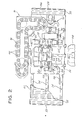
- Fig. 2 is a top plan view of the machining center of Fig. 1;
- Fig. 3 is a view taken substantially along line 3-3 of Fig. 2;
- Fig. 3A is a view in vertical section of one of the tool receiving sockets carried by the endless chains 98 of main
tool storage magazine 90; - Fig. 4'is a plan view of the tool change arm assembly which transfers tools (as defined in the specification) from the main tool storage magazine to the tilt unit and vice versa;
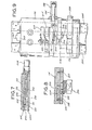
- Fig. 5 is a view taken in section along the line 5-5 of Fig. 4;
- Fig. 6 is a fragmentary longitudinal sectional view taken along line 6-6 of Fig. 5;
- Fig. 7 is a view taken in section along line 7-7 of Fig. 5;
- Fig. 8 is a view in section along line 8-8 of Fig. 5;
- Fig. 9 is a front elevational view of the tool change arm assembly of Fig. 4.
- Fig. 10 is a rear elevational view of the upright which supports the tool change arm assembly of Fig. 4;
- Fig. 11 is a side elevational view of the upright which supports the tool change arm assembly of Fig. 4;
- Fig. 12 is a view partially in vertical elevation and partially in vertical section of the 90° tilt device, with the tilt device being shown in phantom in its horizontal tilted position;
- Fig. 12A is an enlarged view in vertical section of the tilt unit shown in Fig. 12;
- Fig. 13 is an end view of the tilt device of Fig. 12, with the tilt device being shown in its normally vertical position corresponding to the full line view of Fig. 12;
- Fig. 14 is a top plan view of the tilt device of Figs. 12 and 13, partially broken away, showing the operating mechanism for indexing the rotatable small tool carrier or auxiliary tool storage magazine which is positioned on the tilt device during Mode II operation (as defined in the specification);
- Fig. 15 is an enlarged fragmentary portion in elevation of the right-hand end of Fig. 1, showing the tool change arm assembly used for interchanging small tools between the indexable small tool carrier or auxiliary tool storage magazine and the machine tool spindle in operative position preparatory to interchanging small tools between the rotatable small tool carrier and the spindle of the machine tool;
- Fig. 16 is a view of the "other" or second tool change arm of the two selectively operable tool change arms, the second tool change arm being used for interchanging larger diameter tools between the tilt device and the spindle of the machine tool, the second of the tool change arms being shown in operative position in readiness to transfer to the machine tool spindle the adapter which receives the shanks of the small tools when the small tools are being rotatably driven by the machine tool spindle;
- Fig. 17 is a fragmentary plan view, partially broken away, of the tool change housing adjacent the spindle of the machining center;
- Fig. 18 is a view taken along line 18-18 of Fig. 17;
- Fig. 19 is a front elevational view with the front cover cut away of the tool change assembly which is used to interchange large diameter tools between the tilt unit and the machine tool spindle, with the tool change assembly being shown in vertical position;
- Fig. 20 is a front elevational view with the front cover cut away of the tool change assembly of Fig. 19 in its horizontal position;
- Fig. 21 is a fragmentary plan view, partially cut away, of the two selectively operable tool change assemblies which transfer tools (as defined in the specification) between the tilt unit and the spindle of the machining center;
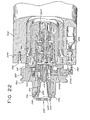
- Fig. 22 is a view in longitudinal section of the spindle of the machine tool, and showing the adapter which receives one small tool mounted on the machine tool spindle for rotation therewith; and
- Fig. 23 is a block diagram of the electrical circuits which control the machine tool, and which also control the automatic tool changer and tool storage arrangement of the invention.
- Referring now to the drawings, and more particularly to Figs. 1 and 2, which show the general arrangement of the apparatus, there is shown in the front elevational view of Fig. 1 and in the plan view of Fig. 2 a horizontal machining center, generally indicated at 10, which is equipped with the automatic tool changer and tool storage arrangement of the present invention. The machining center includes a
bed 50 upon which asaddle 52 is slidably mounted on X-axis ways 54 (Fig. 2).Saddle 52 is driven alongways 54 by a rack and pinion drive which consists of a rack 56 (Fig. 2) onbed 50 and twopinions 58 onsaddle 52 which are driven by aservo motor 60 through a conventional speedreduction gear box 62.Motor 60 is selectively energized by a conventional numerically controlled X-axis servo system (not shown) to movesaddle 52 to any desired position along-the X-axis. - A pair of flexible
metallic cover sheets 53 are coupled between opposite side edges ofsaddle 52 and a corresponding pair ofstorage rollers 55 which are mounted on opposite ends ofbed 50.Cover sheets 53 are both made of relatively narrow interlocked metal slats 57 (Fig. 2) and easily roll up on theirrespective rollers 55. Bothrollers 55 are torsion biased away fromsaddle 52 by motors 59 (Fig. 1) and maintain a tension incover sheets 53 at all times so that eachcover sheet 53 will roll up automatically whensaddle 52 moves toward it, while theopposing cover sheet 53 will be drawn off itsroller 55 against the force of thecorresponding motor 59.Cover sheets 53 protect the portions ofX-axis ways 54 that are not covered bysaddle 52. - A set of Z-
axis ways 64, lying in a horizontal plane, are formed on top ofsaddle 52 perpendicular toX-axis ways 54. An upright 66 is slidably mounted on " Z-axis ways 64 and is driven therealong by a conventional ballscrew drive (not shown) which is powered by a servo motor 68 (Fig. 2).Motor 68 is selectively energized by a conventional numerically controlled Z-axis servo system (not shown) to move upright 66 to any desired position along the Z-axis. - A set of vertical Y-
axis ways 70 are formed on upright 66 perpendicular to bothX-axis ways 54 and Z-axis ways 64. Aspindlehead 72 is slidably mounted on Y-axis ways 70 and is driven therealong by a conventional ballscrew drive (not shown) which is powered by a servo motor 74 (Fig. 2). Motor 74 is selectively energized by a conventional numerically controlled Y-axis servo system (not shown) to movespindlehead 72 to any desired vertical position along the Y-axis. - A hydraulically actuated counterweight system is coupled to
spindlehead 72 to take the weight ofspindlehead 72 off the ballscrew drive therefor. The counterweight system includes two hydraulic piston and cylinder mechanisms 76 (Fig. 1), twocables 78 which are coupled between the respective hydraulic andpiston cylinder mechanisms 76 andspindlehead 72, andpulleys 80 which guidecables 78. Hydraulic piston andcylinder mechanisms 76 apply a'tension tocables 78 which is approximately equal and opposite to the weight ofspindlehead 72 to take the weight ofspindlehead 72 off the ballscrew drive. - A
spindle 82 is rotatably mounted inspindlehead 72 and, as will be explained in more detail later, is sized to receive a "large" tool having a shank of a particular predetermined configuration, size, or diameter (hereinafter referred to in the specification and claims as a "said predetermined size"), such as, for example, a four inch diameter shank. The words "large tool" as used in the specification and claims are intended to include any one of the following: - (1) A single tool having a shank of said predetermined size.
- (2) A multiple spindle toolhead having a shank of said predetermined size, aaid toolhead carrying a plurality of tools which are being driven simultaneously by gearing carried by the multiple spindle toolhead, as shown, for example by Fig. 33 of the aforementioned European Patent Application No. 79104114.8.
- (3) An adapter device having a built-in tool' retention mechanism for holding a tool having a different shank size than said predetermined shank size. For example, the tool supported by the adapter device may be a #50 taper shank tool. The adapter device itself has a shank of said predetermined size and is mounted on and . rotatable with the spindle.
- (4) An indexable carrier or auxiliary-tool storage magazine for supporting a plurality (such as six) of tools. The indexable carrier has a shank of said predetermined size, whereby the carrier may be stored in a socket of the main tool storage magazine. The tools supported by a particular indexable rotary carrier have a shank size different than said predetermined size and may be, for example, #50 taper shank tools. In this case, the tool handling operations are performed in accordance with Mode II operation to be described.
- It should be noted that main
tool storage magazine 90 stores all of the "large" tools just described and thattool receiving sockets 100 of maintool storage magazine 90 are sized to receive the shanks of any of the "large" tools as hereinbefore defined, and also that the socket of the 90° tilt device, and also the socket .of the machine tool spindle is sized to receive the shank of any of the "large" tools, except theindexable carrier 400 which has the proper size shank forspindle 82 but is never transferred to the spindle. - It should also be noted that in either the case of "large" tools or "small" tools, as set forth in the specification and claims, the term "tool" is intended, where applicable, to include the tool element which operates on the workpiece, and also the tool shank which is received in a socket of the main tool storage magazine, of the tilt device, or of the spindle (all in the case of the "large" tools), or in one of the sockets of the auxiliary magazine (in the case of the "small" tools):, or in the socket of the adapter (also in the case of the "small" tools). All of the tools, whether "large" or "small" include a grooved flange which is adapted to be. gripped by the appropriate tool change arm assembly.
-
Spindle 82 is driven in its rotary motion by a spindle motor 84 (Fig. 2) through a set of conventional speed change gears (not shown) to rotatespindle 82 at a desired speed in the desired direction to machine a workpiece 86 (Fig. 2) on aconventional worktable 88 positioned in front ofbed 50. The details ofworktable 88 are omitted since they are not relevant to the automatic tool changer of the present invention. - The automatic tool change of the invention includes:
- . (A) A double-deck main
tool storage magazine 90 which is adapted to store a plurality of any of the "large" tools previously defined, each of the stored "tools" having a shank of said predetermined size or diameter, such as a four inch diameter cylindrical shank.
Maintool storage magazine 90 includestool receiving sockets 100 which are sized to receive the shanks of any of the "large" tools as hereinbefore defined. Since one of the "tools" adapted to be received in thesockets 100 of the maintool storage magazine 90 is the indexable carrier or auxiliarytool storage magazine 400 which supports a plurality of the "small" tools 600 (such as #50 taper shank tools), it therefore follows that maintool storage magazine 90 also serves to store the "small" tools as well as the "large" tools since each indexable carrier or auxiliarytool storage magazine 400 when stored inmain tool magazine 90 is provided with an assortment of "small" tools, different auxiliarytool storage magazines 400 carrying different assortments of "small" tools. - (B) A tilt unit, generally indicated at 92, which is adapted to receive any of the foregoing defined "large" tools which have a shank of said predetermined size or diameter. The
tilt unit 92 is pivotally mounted to tilt from a vertical position, in which the tilt unit receives the tool from the maintool storage magazine 90, to a horizontal position parallel to the axis ofspindle 82, in which it is in a proper plane to transfer the tool to spindle 82.Tilt unit 92 is also adapted to tilt from a horizontal position back to a vertical position. The tilt unit is adapted to receive the indexable carrier or auxiliarytool storage magazine 400.Indexable carrier 400 has a shank of said predetermined size or diameter which is received in a socket forming part of the tilt unit. A drive means is provided for rotatably indexing the socket of the tilt unit and the indexable carrier mounted in the socket, whereby to present a predetermined one of the tools on the indexable carrier to a pick-up station or tool transfer point for transfer to the spindle of the machine tool. - (C) A first tool
change arm assembly 94, which is adapted to transfer any of the foregoing defined "tools" designated at (1), (2), (3) and (4), namely, the single tool, the multiple spindle toolhead, the adapter device, and the indexable small tool carrier or auxiliary tool storage magazine, all of which have a shank of said predetermined diameter, between maintool storage magazine 90 and thetilt unit 92. - (d) A second tool change arm assembly, generally indicated at 96 and comprising a pair of independently operated tool
change arm assemblies change arm assembly 96A is adapted to transfer any one of the "tools" designated at (1), (2) and (3) hereinbefore, namely, the single tool, the multiple spindle toolhead, or the adapter device, all of which have a shank of said predetermined diameter, fromtilt unit 92 tospindle 82.Tool change assembly 96B is adapted to interchange the smaller diameter tools, such as the #50 tapered shank tools, between the indexable carrier or auxiliarytool storage magazine 400 andadapter device 500 mounted inspindle 82. - Main
tool storage magazine 90 is a double-deck structure which supports two endless chains 98 (Fig. 2) oftool sockets 100. As best seen in Fig. 3A, eachtool socket 100 of the endless chains 98 has a hollowcylindrical body 102 which has acentral bore 104 which is of a size to receive a "large" tool of any of the types previously defined having a shank of said predetermined diameter, such as, for example, a four inch diameter straight shank. - A
flange 106 is formed on the top ofbody 102 of eachtool socket 100 for supporting theflange 108 on any of the large tools whose cylindrical shank (such as a four inch diameter straight shank) is received inbore 104 oftool socket 100. As seen in Figs. 2 and 3, each of the endless chains 98 is guided and driven around a corresponding L-shaped path by means of conventional sprockets including a drive sprocket 128 (Figs. 2 and 3) which is driven by a servo motor through a pinion gear engaging drive sprocket 128. Idler sprocket 136 (Figs. 2 and 3) carries a plurality of angularly spaced stop lugs which are spaced apart from each other circumferentially by an angle corresponding to the spacing oftool sockets 100. Suitable proximity switches are positioned in the path of the stop lugs carried by theidler sprocket 136 and produce an output signal whenever one of the lugs carried by the sprocket passes over it whereby to count the tool sockets passing the proximity switch, and thus whereby to determine when a predetermined desired tool socket is in position to transfer or receive a tool received in the tool socket. - When the desired
tool socket 100 is in the predetermined required position to transfer or receive a tool, the drive motor for the tool supporting endless chain is deenergized and suitable means, which forms no part of the present invention, is provided to insure that the desiredtool socket 100 is properly located and oriented attool transfer point 478 to transfer or receive a tool or other device supported in the tool socket. - Fig. 3 shows the supporting structure for
tool storage magazine 90. The rear portion oftool storage magazine 90 at the right side of Fig. 3, is rollably supported on a stationary rail 162 byrollers 164 which are journaled to a base 166. Base 166 is attached to'thelower plate 130 of the lower deck oftool storage magazine 90. A group of spacedposts 168 extend betweenlower plate 130 of the lower deck and thelower plate 132 of the upper deck of thetool storage magazine 90. The front portion oftool storage magazine 90 is slidably supported onbases 170 which extend from the adjacent portion of the X-axis bed 50 (Fig. 1). Abase plate 172 is attached to the adjacent end ofsaddle 52 and slides overbases 170. The front portion oftool magazine 90 is supported bybase plate 172 and thus moves withsaddle 52 over theX-axis bed 50 and bases 170.Base plate 172 also supports tool changearms Upright 66,tool storage magazine 90, toolchange arm assemblies tilt unit 92 all move as a unit withsaddle 52. - Referring to Fig. 2, a first tool change-arm assembly generally indicated at 94 transfers "large" tools (such as the four inch diameter cylindrical shank tools) as previously defined, from main
tool storage magazine 90 to tiltunit 92.Tilt unit 92 is in the position shown in Fig. 16 of the drawings, with piston andcylinder mechanism 390 in extended position, whentilt unit 92 receives a tool from first toolchange arm assembly 94. - Referring to Figs. 4 and 5, first tool
change arm assembly 94 comprises atool gripper arm 174 which is rotatably mounted on abase 176 for rotation about a vertical axis 178 (Fig. 5).Tool gripper arm 174 is rotatable from a forward position, indicated in Fig. 4 by broken outline 174A, to a central position indicated in Fig. 4 by the solid outline 174B, to a rear position indicated in Fig. 4 by broken outline 174C. In the rear position,tool gripper arm 174 picks up a tool fromtool storage magazine 90. In the central position, the tool is placed intilt unit 92. In the forward position,tool gripper arm 174 is clear oftilt unit 92 so that the latter can tilt forward. On the return portion of the cycle,tool gripper arm 174 picks up a tool fromtilt unit 92 in the central position and transfers it totool storage magazine 90 in the rear position. -
Tool gripper arm 174 is rigidly attached to a vertical shaft 184 (Fig. 5) which is rotatably attached tobrackets 186 onbase 176 bybearings 188. Ahorizontal bracket 190 is rotatably attached toshaft 184 bybearings 192 and is moved by a hydraulic piston and cylinder mechanism 194 (Fig. 4) which, in its retracted position, movesarm 174 to its forward position, and which in its extended position, movesarm 174 from its forward position to its central position. Thepiston rod 195 of hydraulic piston andcylinder mechanism 194 is connected tobracket 190 by apivotal connector 196. The other end of hydraulic piston andcylinder mechanism 194 is pivotally connected to abracket 198 onbase 176. - A bracket 200 (Fig. 5) is attached to a
projection 201 ofbracket 190 bymachine screws 203.Bracket 200 provides a pivotal mounting for another hydraulic piston andcylinder mechanism 202 which is pivotally coupled betweenbrackets cylinder mechansim 202 is pivotally coupled to a bracket 208 (Fig. 5) ontool gripper arm 174 by apivotal connector 210. Hydraulic piston andcylinder mechanism 202, when extended, movesarm 174 from its central position 174B (Fig. 4) to its rear position, indicated by broken outline 174C in Fig. 4. When hydraulic piston andcylinder mechanism 202 is retracted, it movesarm 174 from its rear position 174C to its central position, indicated by the solid line position 174B in Fig. 4. A pair of cam actuatedlimit switches 212 and 214 (Figs. 5 and 9) indicate whenarm 174 is in the forward, central or rear position.Limit switch 212 is actuated bycam 216 andlimit switch 214 is actuated bycam 218. Bothcams shaft * 219 which is attached toshaft 184. - A semicircular gripper cavity 220 (Fig. 4) is formed in the end of
arm 174. A pair ofrollers 222 and amovable jaw member 224 are movably mounted inarm 174 and are positioned aroundgripper cavity 220 in position to grip the grooved flange provided on each of the tools to securely hold the tool inarm 174 for transfer.Movable jaw member 224 is slidable inslot 226 inarm 174 between an extended position shown in Fig. 4 and a retracted position (not shown) in whichjaw member 224 is completely withdrawn intoslot 226.Jaw member 224 is moved back and forth between its extended and retracted positions by a hydraulic piston andcylinder mechanism 228 which moves aslide 230 in a slot 231 (Fig. 6) crossways ofjaw member 224.Slide 230 has a raised cam portion 232 (Fig. 6) which extends at a 45° angle (to the edge ofslide 230 and slidably engages acam slot 234 injaw 224.Cam slot 234 extends at the same angle a of 45° to the edge ofjaw member 224 and interacts with the raisedcam portion 232 ofslide 230 to movejaw member 224 between its extended and retracted position. - When hydraulic piston and
cylinder mechanism 228 is extended,jaw member 224 is retracted and when hydraulic piston andcylinder mechanism 228 is retracted, as shown in Fig. 6,jaw member 224 is extended. - The tip 236 (Fig. 6) of
cam portion 232 and the adjacent portion ofslot 234 are angled at a small angle β to the edge ofslide 230 to provide for a reduced rate of movement at the end of the retraction stroke of hydraulic piston andcylinder mechanism 228 to lock the tool ingripper jaw cavity 220. Movement of cam portion .232 along theedge 236 will continue untiljaw member 224 exerts enough pressure on the tool therein to counteract the retraction force of hydraulic piston andcylinder mechanism 228. - Referring to Figs. 5, 7 and 8, the bottom of
slot 226 intool gripper arm 174 is closed by acover plate 238 which is attached togripper arm 174 bymachine screws 240. The end ofslot 231 is closed by a cover plate 242 (Figure 7) which is attached to gripper'arm 174 bymachine screws 244. A limit switch 246 (Figs. 5 and 8) is mounted on the bottom ofcover plate 238 bymachine screws 248. A spring loaded plunger 250 (Fig. 8) bears against the bottom ofgripper jaw 224 and actuates switch 246 whengripper jaw 224 is in its retracted position. -
Tool gripper base 176 is slidably mounted for vertical movement on an upright 252 (Figs. 4, 10 and 11). A set of vertical ways 254 (Figs. 4, 9 and 11) are formed onupright 252 to guide the vertical movement oftool gripper base 176. Two vertical movements are required forbase 176. The first is a short upward movement to lift a tool from thetool storage socket 100 with whichtool gripper arm 174 is aligned, along with the complementary short downward movement to lower a tool into thetool storage socket 100. The second vertical movement is a longer upward movement to raisetool gripper arm 174 from the lower deck oftool storage magazine 90 to the upper deck thereof, along with the complementary downward movement to lowertool gripper arm 174 from the top deck to the lower deck. - These.two movements are obtained by two hydraulic piston and
cylinder mechanisms 256 and 258 (Fig. 10) which are connected together in tandem, the base of thelonger cylinder 258 being connected to and supported by the end of the piston rod of the shorter piston andcylinder mechanism 256. The end of thepiston rod 260 of the longer piston andcylinder mechanism 258 is attached to abracket 262 on the top oftool gripper base 176 by a machine screw 264 (Figs. 9 and 10). Figs. 10 and 11 show the longer piston andcylinder mechanism 258 in its fully extended position and the shorter piston andcylinder mechanism 256 in its fully retracted position. This placestool gripper arm 174 in position to pickup a tool from the upper deck oftool storage magazine 90. After the tool has been gripped bygripper arm 174 it is lifted out of itsocket 100 by extension of piston andcylinder mechanism 256. Then, aftertool gripper arm 174 has been swung clear oftool storage magazine 90, both piston andcylinder mechanisms tilt unit 92. - With both piston and
cylinder mechanisms tool gripper arm 174 is vertically positioned to grip a tool in the lower deck oftool storage magazine 90. An extension of piston andcylinder mechanism 256 will then lift the gripped tool out of itssocket 100. Thetool gripper arm 174 is then swung over tilt unit 92 (see Fig. 2) and piston andcylinder mechanism 256 is retracted to drcp the tool intotilt unit 92. - Four
limit switches upright 252 and interact with the adjacent edge oftool gripper base 176 to indicate which of the four possible vertical positions that base 176 is in at any time. - Tool
change arm assembly 94 and the associated structure just described in connection with Figs. 4-11, inclusive, are substantially the same as disclosed in connection with Figs. 10-17, inclusive, of the aforementioned European Patent Application No. 79104114.8. - Figs. 12, 13 and 14 show the details of the
tilt unit 92 which'is adapted to receive a "large" tool of any of the types previously defined from first toolchange arm assembly 94. The shank of the tool being transferred, as stored in maintool storage magazine 90 and as received by first toolchange arm assembly 94, is in a vertical position. After having received the transferred tool from toolchange arm assembly 94,tilt device 92 tilts the tool through an angle of 90° whereby the shank of the tool is then in a common horizontal plane withrotatable spindle 82 of the machine tool. -
Tilt unit 92 comprises ahousing 274 having - pivotally connected thereto anarm 276, which is pivotally attached to a pair of upstandingtriangular sides 278 • bytrunnions 280.Triangular sides 278 are bolted tobase plate 282. - Housing 274 can be pivotally moved from a vertical position, shown in solid lines in Fig. 12, to a horizontal position, shown in broken lines in Fig. 12, by extension and retraction of two hydraulic piston and
cylinder mechanisms 284, which are pivotally connected at one end tobase plate 282 and are pivotally connected at the other end tohousing 274. Withinhousing 274 there is positioned a cup-like socket generally indicated atsocket 290. Within the hollow interior ofsocket 290, there is positioned acollet clamp 292 of generally hollow cylindrical shape. Rigidly secured to or integral withclamp 292 is a base portion 294, which is fixed to or otherwise secured to ashaft 296.Shaft 296 passes downwardly through a passage 299 inbase portion 302 ofsocket 290,shaft 296 passing belowbase portion 302, withshaft 296 being provided at the lower portion thereof with a shoulder 304 upon which are seated a plurality of Belleville springs 306 which urgeshaft 296 in a downward direction whereby to movecollet clamp 292 to clamped position. A short hydraulic piston andcylinder mechanism 308 is mounted at the lower end ofhousing 274 and includes a piston rod 310 which underlies but is not positively connected to the lower end ofshaft 296 carried bycollet clamp 292. When hydraulic piston andcylinder mechanism 308 is actuated to move piston rod 310 to an extended position, piston rod 310 bears against the lower end ofshaft 296 of the collet mechanism and movescollet clamp 292 to unclamped position against the force of Belleville springs 306.Collet clamp 292 serves to clamp the cylindrical shank of any "large" tool which may be received bysocket 290. - In the view shown in Fig. 12,
shank 402 of indexable carrier or auxiliarytool storage magazine 400 is shown mounted insocket 290 oftilt device 92.Carrier 400 is provided with a plurality of angularly spaced sockets for receiving a plurality, such as six of the individual small tools each generally indicated at 600 which are adapted to be transferred by toolchange arm assembly 96B to theadapter 500 onspindle 82.Adapter 500 is provided with a built-in small tool retention mechanism as will be explained in more detail hereinafter. However,socket 290 oftilt device 92 can also receive the shank of any of the other "large" tools as hereinbefore defined, including (1) the shank of a single tool, such as, for example, a tool of the type illustrated in Fig. 39 of the aforementioned European Patent Application No. 79104114.8; (2) the shank of a multiple spindle toolhead such as that shown by Fig. 33 of the aforementioned European Patent Application No. 79104114.8; or (3) the shank of adapter 500 (Fig. 22) for retaining a single "small"tool 600 inspindle 82. - A
flange member 312 oftilt device 92 is secured to the upper end of cylindrical socket member 290-and the drivenmember 316 of a Geneva drive mechanism generally indicated at 314 is secured to or is an integral part offlange 312. The under surface offlange 312 rests on the upper end of outer casing orhousing 274 oftilt device 92.Drive member 315 of the Geneva drive mechanism is in driving relation with the Geneva drivenmember 316.Geneva drive member 315 is rotatably driven by asingle revolution motor 318.Motor 318 may be operated by any suitable power means and may be electrically or hydraulically operated for example. - Geneva mechanisms are well-known per se. As best seen in Fig. 14,
drive member 315 of the Geneva mechanism is provided with apin member 320 which engages angularly spaced slots 332 in the outer periphery,of the Geneva drivenmember 316, whereby one rotation ofdrive member 315 indexes drivenmember 316 and hence indexable carrier or auxiliarytool storage magazine 400 by one angular step. Therefore it can be seen that if the indexable carrier or auxiliarytool storage magazine 400 has six angularly spaced "small" tools supported thereby, and if the Geneva drivenmember 316 is provided with a corresponding number of slots engaged bypin 320 ofGeneva drive member 315, that each rotation ofGeneva drive member 315 will cause auxiliarytool storage magazine 400 to index through one angular step whereby to permit indexing a predetermined desired smallrotary tool 600 into proper position for transfer toadapter 500 oftool spindle 82. - During the "Mode I" operation of the tool changing operation, as will be explained hereinafter, when
rotary carrier 400 is not mounted ontilt unit 92, theGeneva mechanism 314 is not in use andmotor 318 is deenergized. - In Mode I operation,
Geneva drive member 315 is stopped in a "park" position in whichedge 315A ofGeneva drive member 315 abuts againstedge 316A of Geneva drivenmember 316 to thereby stabilize therotatable socket member 290 to which Geneva drivenmember 316 is secured, and to prevent rotation or other movement ofsocket member 290 during Mode I operation. - As best seen in Figs. 1, 2, 15, 16, 17, 18 and 21, two tool change arm assemblies, respectively generally indicated at 96A and 96B, are provided to effectuate the interchange of tools between 90°
tilt device 92 andmachine tool spindle 82. Toolchange arm assembly 96A serves the function of transferring large shank diameter tools betweentilt device 92 andspindle 82. Tooltransfer arm assembly 96B is used only in Mode II operation and serves the function of transferring small shank diameter tools, such as the #50 taper shank tools, between indexable carrier or auxiliarytool storage magazine 400 mounted intilt device 92 andadapter 500 carried byspindle 82 for receiving and holding small diameter tools. - As best seen in Figs. 17, 18 and 21, tool
transfer arm assemblies coaxial shafts transfer arm assembly Shaft 351 is the outer shaft and is positioned coaxially aboutinner shaft 353.Outer shaft 351 andinner shaft 353 are capable of rotating independently of each other. - The two
coaxial shafts transfer arm assemblies transfer arm assemblies -
Outer shaft 351 is circumferentially slotted at 357 to receive a pair of rollers 358 (Fig. 21) which are mounted on ayoke 361.Yoke 361 is moved axially back and forth (right and left in Fig. 21) by a hydraulic piston andcylinder mechanism 363 whosepiston rod 365 is rigidly attached toyoke 361. Any axial movement ofyoke 361 causes a corresponding axial movement of both outer andinner shafts coaxial shafts snap ring 354 therein.Snap ring 354 projects beyond the outer periphery ofinner shaft 353 and is received in a groove defined by aretainer 356 mounted at the contiguous outer end ofouter shaft 351. This arrangement causesshafts shafts piston rod 365 is extended, it moves both tooltransfer arm assemblies piston rod 365 is retracted, it moves bothtool transfer assemblies - A spur gear 367 (Fig. 21) is rigidly attached to
inner shaft 353 contiguous the rear (right-hand in Fig. 21) end ofinner shaft 353 and engages arack 369 whencoaxial shafts Rack 369 is moved linearly by a hydraulic piston andcylinder mechanism 371 whosepiston rod 373 is attached to rack 369 and whose cylinder is attached to abracket 374 onupright 355. The full stroke ofrack 369 rotatesinner shaft 353 through 90° to rotatetool transfer arm 96B from its vertical or "parked" position shown in Fig. 16 to its horizontal operative position shown in Figs. 1 and 15. The vertical position of tooltransfer arm assembly 96B is the stand-by position, and the horizontal position thereof is the tool pick-up or deposit position. - In a similar manner, a
spur gear 376 is rigidly attached toouter shaft 351 and engages arack 378 whenshaft 351 is in its rear position shown in solid lines in Fig. 21.Rack 378 is moved linearly by a hydraulic piston andcylinder mechanism 380 whosepiston rod 382 is attached to rack 378 and whose cylinder is attached tobracket 374 onupright 355. Piston andcylinder mechanism 380 andrack 378 are all so dimensioned that one-half of the full stroke ofpiston rod 382 causes a 90° movement ofouter shaft 351 to thereby rotate toolchange arm assembly 96A from its vertical position (shown in Figs. 1 and 15) to its horizontal position shown in Fig. 16. The vertical position of toolchange arm assembly 96A is the stand-by position and the horizontal position thereof is the tool pick-up or deposit position. - When
outer shaft 351 and tooltransfer arm assembly 96A are in their forward position, shown by broken lines in Fig. 21,gear 376 carried byouter shaft 351 is aligned with a second rack 384 (Fig. 21). The piston rod 386 of piston andcylinder mechanism 385 is attached to rack 384 and piston rod 386 andrack 384 are so dimensioned that the full stroke of piston rod 386 rotatesouter shaft 351 and toolchange arm assembly 96A through 180° to interchange the ends of toolchange arm assembly 96A. This rotation through 180° only occurs whenshaft 351 and toolchange arm assembly 96A are in their forward position shown by broken lines in Fig. 21. In the axially forward position ofshaft 351, the tools supported by toolchange arm assembly 96A do not lie within a retaining socket, either in the spindle contiguous one end of toolchange arm assembly 96A, or in the socket carried bytilt device 92 contiguous the opposite end of the toolchange arm assembly 96A. - When
inner shaft 353 and tool change or transferarm assembly 96B are in their forward position, shown by broken lines in Fig. 21,gear 367 carried byinner shaft 353 moves into alignment withrack 378 of piston andcylinder mechanism 380. Movement ofpiston rod 382 to its full stroke rotatesinner shaft 353 and toolchange arm assembly 96B through 180° to interchange the ends thereof in the same manner as described hereinbefore in connection with toolchange arm assembly 96A. - Tool
change arm assembly 96A comprises a tool gripper arm 298 (Figs. 19 and 20) which is similar totool gripper arm 298 of the aforementioned U.S. Patent Application Serial No. 954,438, filed October 25, 1978, as shown in and described in connection with Figs. 25 and 26 of that application.Tool gripper arm 298 has opposedtool gripper cavities 344 and 346 which containrollers 348.`Rollers 348 are dimensioned and positioned to fit in a standard grooved flange on any of the "large" tools as hereinbefore defined. A pair of rotarytool gripper jaws arm 298 adjacent to grippercavities 344 and 346.Tool gripper jaws gripping segments Gripper jaws gripping segments tool cavities 344 and 346, respectively. The movement ofgripping segments tool cavities 344 and 346 is limited by the abutment of thestraight edges gripper jaws - A
cam 360 with an open position shown in solid lines in Fig. 19 and a locked position shown in broken lines in Fig. 19 is rotatably mounted betweengripper jaws gripper jaws respective tool cavities 344 and 346 to inserttool grip segments tools tool gripper jaws cam 360, which abuts against thestraight edges jaws tools tool cavities 344 and 346, respectively.Cam 360 is mounted to be able to float laterally to equalize clamping pressure. To releasetools cam 360 must be rotated 90° counterclockwise from the position shown in Fig. 20 back to the position shown in solid lines in Fig. 19. This permitstool gripper jaws tool cavities 344 and 346, respectively. - Referring to Figs. 20 and 21,
cam 360 is attached to a shaft 375 (Fig. 21) which extends through the hollow interior ofinner shaft 353. The rear end of shaft 375 (on the right side of Fig. 21) is connected to a hydraulicrotary actuator 377, such as manufactured by the Flo-Tork Company, Orrville, Ohio, U.S.A.Rotary actuator 377 acts to rotateshaft 375 by 90° clockwise or counterclockwise in response to electrical signals. The 90° rotation ofshaft 375 rotatescam 360 between its open and locked position as described previously. -
Tool 366 in Fig. 19 is inspindle 82 whiletool 368 is intilt unit 92. To exchangetools upright 66,saddle 52, andspindlehead 72 are moved by the N.C. axis servo systems to the positions shown in Figs. 1 and 2.Tool change arm 298 is then rotated 90° counterclockwise from the position shown in Figs. 1 and 19 to the position shown in Fig. 20. Astool cavities 344 and 346approach tools flat edges gripper jaws gripper segments respective tools Gripper segments cam 360 by 90° counterclockwise to the position shown in Fig. 20. - To unlock
gripper jaws cam 360 is rotated 90° clockwise in Fig. 20, which releasesgripper jaws tools - Although the operation of
tool change arm 298 has been described in connection with tools on both ends of the arm, it will work as well with a single tool at either end of the arm. - As best seen in Figs. 15 and 16, the 90°
tilt device 92 is mounted for axial sliding movement from right to left (or vice versa) with respect to the views shown in Figs. 1, 2, 15 and 16. The motive power for the axial adjusting movement oftilt device 92 is provided by a piston and cylinder assembly, generally indicated at 390, including ahydraulic cylinder 392 which is suitably anchored at one of its ends to the stationary structure and apiston rod 394 which is pivotally connected to amember 395 which forms part of the tilt device structure. In the position shown in Fig. 15,piston rod 394 is retracted intocylinder 392, and the slidably mountedtilt device 92 is at the extreme right end of its possible path of movement of travel. The position oftilt device 92 shown in the view of Fig. 15 is the location of the tilt device when toolchange arm assembly 96B which interchanges the "small" tools between auxiliarytool storage magazine 400 andspindle 82 is in use. When toolchange arm assembly 96A which interchanges large size shank tools betweentilt unit 92 andspindle 82 is in use, slidablymovable tilt device 92 is in the position shown in Fig. 16. In moving from the Fig. 15 position to the Fig. 16 position, or vice versa,tilt unit 92 moves a distance equal to the radius of rotary carrier or auxiliarytool storage magazine 400. The reason for providing this capability for shifting thetilt device 92 from the position shown in Fig. 15 corresponding to the retracted position ofpiston rod 394, and the position shown in Fig. 16 corresponding to the extended position of thepiston rod 394 is that the two selectively operable tooltransfer arm assemblies change arm assemblies tilt device 92 in the manner just described. - The tool change assembly generally indicated at 96B, for interchanging small tools, such as the #50 taper shank tool, between
spindle 82 and indexable carrier orauxiliary magazine 400 is similar to thetool change mechanism 172 shown in United States Patent 3,704,510 issued to Robert K. Sedgwick et al on December 5, 1972. In view of the fact that thetool change mechanism 96B is shown in a prior issued patent, it is not believed necessary to show or describe thetool change mechanism 96B in detail in the present application. However, it will be noted, as seen in Fig. 21, thatshaft 375 has a hollow axial passage therethrough for the entire length ofshaft 375, and ashaft 379 extends through the hollow passage ofshaft 375 and has a pinion (not shown) mounted at the left-hand end thereof (relative to Fig. 21) to actuate a rack which forms part oftool change assembly 96B, whereby to actuatetool grips 396 and 397 (Fig. 15). - Referring to Fig. 22, there is shown the
adapter member 500 in assembled relation tomachine tool spindle 82.Adapter 500, as seen in Fig. 22, receives thesmall tool 600 from indexable carrier or auxiliarytool storage magazine 400. The spindle assembly comprises a cylindricalstationary housing 502 for the rotatable spindle82. Aspindle bearing retainer 504 is secured tostationary spindle housing 502 bybolts 506. Aroller bearing assembly 508 is interposed between therotatable spindle 82 andstationary housing 502. The outer or left-hand end ofspindle 82 is provided with a socket 510 which receives a collet member 512.Spindle 82 is provided with aface plate 514 which is bolted to the spindle by bolt members (not shown).Face plate 514 is keyed tospindle 82 as indicated at 516. The purpose ofkey 516 betweenspindle 82 andface plate 514 is to relieve shearing stress on the bolts which secure the face plate to the spindle. Another function of the key 516 is to insure proper orientation of the tool, such as theadapter member 500, which is secured to the spindle. Theadapter 500, as in the case of any other tool which might be received byspindle 82, is provided with a large diameter shank 518, such as a four inch diameter shank for example. Large.diameter shank 518 is received by collet 512 in socket 510 at the left-hand end ofspindle 82. Shank 518 ofadapter 500 is suitably secured toadapter body 520 bybolts 522. A drawrod 524 is in threaded engagement with collet 512. Drawrod 524 is pulled to the right relative to the view in Fig. 22 by a suitable piston and cylinder mechanism (not shown) to thereby cause collet member 512 attached thereto to tightly grip shank 518 of the tool, such asadapter member 500, received byspindle 82. When collet 512 is moved into clamping and gripping engagement to adapter shank 518, it not only grips the adapter shank, but also centers the adapter shank relative to the axis ofspindle 82. - To supplement the action of the drawrod 524 just described, a second drawrod or
tool retention rod 526 is threaded and keyed to anadapter member 528 which, in turn is threaded into asecond adapter member 530, which is secured to tool shank 518.Adapter 530, in effect, is an integral part of tool shank 518. Thus, it can be seen that by pulling to the right (relative to Fig. 22) ontool retention drawrod 526,adapter 500 is pulled up tight against theface plate 514 ofspindle 82. -
Adapter 500 is provided with acylindrical passage 532 therethrough, an in the left-hand end of this passage with respect to the view of Fig. 22, ataper adapter member 534 is positioned and is provided with aperipheral flange 536 which is bolted to the forward end ofadapter 500 bybolts 538. Asmall tool 600 received from auxiliarytool storage magazine 400 is shown positioned intaper adapter 534. - The following procedure is followed to install the tapered
shank tool 600 in taper adapter 534: - (1) The hydraulic piston-cylinder assembly 540 (Fig. 22) is actuated to couple the previously uncoupled quick-
disconnect member 542 to permit flow of hydraulic fluid from a stationary supply source throughpassages collet clamp member 550 to the left to an unclamped position relative to collet 552.Collet clamp 550 is attached to and moves with piston member 546. Whencollet clamp 550 has been moved to the left to the unclamped position as just described by the moveHTentof piston 546, the felxible collet member 552 expands radially outwardly into recess 550A of thecollet clamp 550. With the collet 552 expanded radially outwardly to an open position as just described,tapered shank tool 600 may then be inserted intotaper adapter 534 untilneck 602 at the inner end of thetaper shank tool 600 is received by collet 552. When taperedshank tool 600 has thus been installed in position, the hydraulic fluid is released from behind piston member 546 by opening a suitable valve to dump the hydraulic fluid to sump. Belleville springs 548 will then force piston member 546 to the right relative to the view of Fig. 22, pullingcollet clamp member 550 to the right to the position shown in the view of Fig. 22 in whichcollet clamp 550 is in clamping engagement relative to tool retention collet 552 to thereby secure taperedshank tool 600 securely in position intaper adapter 534. - As just explained, hydraulic fluid is applied against piston 546 to cause movement of
collet clamp 550 to permit opening up of collet 552 to either receive ataper shank tool 600 which is to be inserted intaper adapter 534 or to release ataper shank tool 600 which is already in place intaper adapter 534. After removing a giventaper shank tool 600 from thetaper adapter 534 withcollet clamp 550 in unclamped position piston 546 is permitted to remain hydraulically pressurized so that collet 552 will be in proper unclamped condition to receive the next "small" tool to be inserted intotaper adapter 534. - The horizontal machining center and tool change mechanism hereinbefore described essentially has two different modes of operation which may be briefly summarized as follows:
- Mode I: In this mode of operation, the only tools used by the
machine tool spindle 82 are the "large" tools (as hereinbefore defined) having the predetermined diameter or size corresponding to the socket size of the maintool storage magazine 90, to the socket size oftilt device 92, and to the socket size ofspindle 82 without usingadapter 500. - Mode II: In this mode of operation, the indexable rotary carrier of auxiliary tool storage magazine 400 (Figs. 12-16, inclusive) is mounted on
tilt device 92 and "small"tools 600 from auxiliarytool storage magazine 400 are transferred bytool change assembly 96B toadapter 500 inmachine tool spindle 82. - An illustrative tool change cycle in accordance with Mode I will now be described, assumina that the following initial conditions prevail.
- (A) Tool No. 1 having a shank of said predetermined diameter is clamped in
spindle 82 and is being used to machine a workpiece 86 (Fig. 2) onworktable 88. - (B) The
empty tool socket 100 for tool No. 1 is at the tool transfer position in the upper deck of maintool storage magazine 90. - (C) The next tool to be used, tool No. 2, also having a shank of said predetermined diameter, is in a
socket 100 in the upper deck of maintool storage magazine 90 in a known position. - (D)
Tilt unit 92 is empty and is in the vertical position shown in Fig. 16. This is the normal position oftilt unit 92 except when small tools are being interchanged betweenrotary carrier 400 andspindle 82 during a portion of Mode II operation to be described later. - (E)
Tool change arm 174 of first toolchange arm assembly 94 is in the central position opposite the lower deck of maintool storage magazine 90. - (F)
Tool change arm 96A betweentilt unit 92 andspindle 82 is empty on both ends and is in the vertical rear position. - Under the foregoing initial conditions, the tool change cycle operating in accordance with Mode I will proceed as follows:
- (1) While
workpiece 86 is being machined, the motor which drives the upper deck of maintool storage magazine 90 is energized in the forward direction to movetool sockets 100 past the tool transfer position shown atpoint 478 in Fig. 2. - (2) The number of times that lugs carried by idler sprocket 136 (Figs. 2 and 3) pass over a proximity switch along the path of movement of the lugs and are counted by a conventional counter determines when the known position of the
tool socket 100 containing the desired tool No. 2 is attool transfer point 478. - (3) When the desired tool No. 2 is at
tool transfer point 478, the drive motor for the upper deck of maintool storage magazine 90 is deenergized and the desiredtool socket 100 containing tool No. 2 is caused to be located attool transfer point 478. - (4) Hydraulic piston and cylinder mechanism 258 (Figs. 10 and 11) is extended to raise
tool change arm 174 of the first toolchange arm assembly 94 to the level of the upper deck of main tool storage magazine-90. - (5) Hydraulic piston and cylinder mechanism 202 (Fig. 4) is extended to move
tool change arm 174 totool transfer point 478. This places tool cavity 220 (Fig. 4) around the V-groove of tool No. 2. - (6) Hydraulic piston and cylinder mechanism 228 (Fig. 4) is retracted to move gripper
jaw 224 into contact with the V-groove of tool No. 2 to clamp it toarm 174. - (7) Hydraulic piston and cylinder mechanism 256 (Figs. 10 and 11) is extended to lift tool No. 2 out of
tool socket 100. - (8). Hydraulic piston and cylinder mechanism 308 (Fig. 12) is extended to open
collet clamp 292 intilt unit 92. - (9) Hydraulic piston and cylinder mechanism 202 (Fig. 4) is retracted to swing tool No. 2 over
tilt socket 290 oftilt unit 92. - (10) Hydraulic piston and cylinder mechanism 256 (Fig. 10) is retracted to lower tool No. 2 into
tilt socket 290 oftilt unit 92. - (11) Hydraulic piston and cylinder mechanism 228 (Fig. 4) is extended to release gripper
jaw 224 from tool No. 2. - (12) Hydraulic piston and cylinder mechanism 308 (Fig. 12) is retracted to permit Belleville springs 306 to close
collet clamp 292 oftilt unit 92. - (13) Hydraulic piston and cylinder mechanism 194 (Fig. 4) is retracted to swing
tool change arm 174 to its forward position indicated at dotted line 174A in Fig. 4. - (14) Hydraulic piston and cylinder mechanisms 284 (Figs. 12, 13 and 14) are extended to
swing tilt socket 274 oftilt device 92 and tool No. 2 therein to a horizontal position. - The foregoing steps 1 through 14 or any desired portion thereof can be performed while workpiece 86 (Fig. 2) is being machined by tool No. 1 which was placed in
spindle 82 during the preceding tool change. Step 15, however, cannot be performed until the current machining operation onworkpiece 86 is completed. - (15) The X, Y, and Z axes drives for the machine tool are actuated to bring
spindle 82 into the tool change position shown in Figs. 1 and 2, and rotation ofspindle 82 is stopped. - (16) Hydraulic piston and cylinder mechanism 380 (Fig. 21) is extended to rotate
tool change arm 298 oftool change assembly 96A by 90° from the vertical to the horizontal position. - (17) Hydraulic rotary actuator 377 (Fig. 21) is rotated counterclockwise 90° to lock cam 360(Figs. 19 and 20) against
tool grip jaws - (18) Drawrod 524 is pushed to the left relative to the view in Fig. 22 by a suitable hydraulic piston and cylinder arrangement to thereby release collet member 512 from the shank of tool No. 1. Also,
tool retention rod 526 is pushed to the left relative to the view in Fig. 22 by a suitable piston and cylinder mechanism to release tool No. 1 from its engagement with theface plate 514 ofspindle 82.Tool retention rod 526 andadapter member 528 secured thereto (Fig. 22) are then rotated by a suitable means (not shown) carried by the stationary structure to causeadapter member 528 to become disengaged from its screw-threaded engagement with an adapter member such as adapter member 530 (Fig. 22) which is secured to the shank of tool No. 1. Thisdis- connectstool retention rod 526 from tool No. 1. - (19) Piston and cylinder mechanism 308 (Fig. 12) is extended to open
collet clamp 292 intilt unit 92. - (20) Piston and cylinder mechanism 363 (Fig. 21) is retracted to pull tool No. 1 out of
spindle 82 and to pull tool No. 2 out oftilt socket 290 oftilt device 92. - (21) Piston and cylinder mechanism 385 (Fig. 21) is extended to rotate
tool change arm 298 oftool change assembly 96A by 180° to interchange tool No. 1 and tool No. 2. - (22) Piston and cylinder mechanism 363 (Fig. 21) is extended to insert tool No. 2 into
spindle 82 and to insert tool No. 1 intotilt socket 290 oftilt device 92. - (23) Hydraulic rotary actuator 377 (Fig.. 21) is rotated clockwise 90° to unlock cam 360 (Figs. 19 and 20) from
tool grip jaws - (24) Drawrod 524 (Fig. 22) is pulled to the right relative to the view in Fig. 22 by a suitable hydraulic piston and cylinder mechanism to thereby cause collet member 512 to grip the shank of tool No. 2 which is now in the socket of
spindle 82.Tool retention rod 526 andadapter member 528 secured thereto are rotated by a suitable means (not shown) carried by the stationary structure to causeadapter member 528 to threadedly engage an adapter member such as adapter member 530 (Fig. 22) which is secured to the shank of tool No. 22.Tool retention rod 526 is then pulled to the right relative to the view in Fig. 22 by a suitable piston and cylinder mechanism to pull tool No. 2 up tight againstface plate 514 ofspindle 82. - (25) Hydraulic piston and cylinder mechanism 308 (Fig. 12) is retracted to permit Belleville springs 306 6o
close collet clamp 292 intilt unit 92. - (26) Piston and cylinder mechanism 380 (Fig'. 21) is retracted to rotate
tool change arm 298 oftool change assembly 96A from the horizontal to the vertical position. After this step, machining of the workpiece can begin again with the new tool. - (27) Piston and cylinder mechanisms 284 (Fig. 12) are retracted to tilt tool No. 1 in
tilt socket 274 oftilt device 92 to the vertical position. - (28) Piston and cylinder mechanism 194 (Fig. 4) is extended to swing
tool change arm 174 overtilt socket 290 oftilt unit 92. - (29) Piston and clyinder mechanism 228 (Fig. 4) is retracted to move gripper
jaw 224 into contact with tool No. 1. - (30) Hydraulic piston and cylinder mechanism 308 (Fig. 12) is extended to open
collet clamp 292 insocket 290 oftilt unit 92. - (31) Piston and
cylinder mechanisms 256 and 258 (Figs. 10 and 11) are both extended to raise tool No. 1 above the level of the upper deck of maintool storage magazine 90. - (32) Piston and cylinder mechanism 202 (Fig. 4) is extended to move tool No. 1 to tool transfer position 478 (Figs. 2 and 4).
- (33) Piston and cylinder mechanism 256 (Figs. 10 and 11) is retracted to drop tool No. 1 into
tool socket 100 of maintool storage magazine 90. - (34) Piston and cylinder mechanism228 (Fig. 4) is extended to move gripper
jaw 224 out of contact with tool No. 1. - (35) Piston and cylinder mechanism 202 (Fig. 10) is retracted to move
tool change arm 174 to its central position. - This completes the tool change cycle for tools No. 1 and No. 2 involved in Mode I operation.
- The following is a description of the Mode II operation in accordance with which the rotary carrier or auxiliary tool storage magazine 400 (Figs. 12-16, inclusive,) is mounted on
tilt device 92 and "small"tools 600 from auxiliarytool storage magazine 400 are transferred tomachine tool spindle 82 which is provided for this Mode of operation with an adapter member 500 (Fig. 22). As previously described,adapter 500 is provided with a special tool retention mechanism for retaining a single "small"tool 600 used in Mode II operation. - In certain respects, the various tool handling operations which are performed in the Mode II operation are the same as or similar to corresponding operations in Mode I operation. To that extent, the operations in Mode II operation which are similar to corresponding steps- in Mode I operation will not be described again in any detail.
- In describing the Mode II operation, it will be assumed, for simplicity of description, that
spindle 82 does not have a tool of any kind therein at the beginning of the tool change cycle for Mode II operation. It will also be assumed thattilt unit 92 is empty and is in the vertical position of Fig.16 corresponding to Mode I operation. It will also be assumed that toolchange arm assembly 96B, which is used for transferring "small" tools betweentilt unit 92 andspindle 82, is empty on both ends and is in the vertical rear position (i.e., the full line position in Fig. 21). - It is inherent in Mode II operation that the first "tool" to be transferred out of main
tool storage magazine 90 is the adapter member 500 (Fig. 22) and that the second "tool" to be transferred out of maintool storage magazine 90 is a carrier member or auxiliary tool storage magazine 400 (Figs. 12-16, inclusive,) having, a predetermined assortment of "small" tools (such as #50 taper shank tools) positioned thereon. Theadapter member 500 and the auxiliarytool storage magazine 400 which may be one of a plurality of auxiliarytool storage magazines 400 having different assortments of "small" tools are in two different predetermined sockets in the upper deck of maintool storage magazine 90 in two known positions. -
Adapter unit 500 which is to be mounted onspindle 82 is transferred from the upper deck of maintool storage magazine 90 to the socket of spindle-82 by a series of steps substantially corresponding to the steps 1-24, inclusive, described in Mode I operation in describing the transfer of "tool No. 2" in Mode I operation from the upper deck of maintool storage magazine 90 to thespindle 82, sinceadapter 500 is merely another "large" tool having a cylindrical shank of said predetermined diameter, such as a four inch diameter shank. Substantially, the only different between steps 1-24, inclusive, of Mode I operation hereinbefore described and the corresponding steps used for transferringadapter unit 500 from the upper deck of maintool storage magazine 90 tospindle 82 in Mode II operation is that it is assumed, in order to simplify the description of the Mode II operation, thatspindle 82 is empty at the beginning of Mode II operation and hence under the assumed conditions, there is no tool No. 1 already inspindle 82 which is to be transferred back to maintool storage magazine 90 as in the description of Mode I. - With the
adapter member 500 received in socket 510 of spindle 82 (Fig. 22) as just described, the following steps are followed in proceeding with Mode II operation: - (1) Drawrod 524 is pulled to the right relative to the view in Fig. 22 by a suitable piston and cylinder mechanism to cause collet 512 attached to drawrod 524 to tightly grip shank 518 of
adapter member 500. When collet 512 is moved into clamping and gripping engagement to adapter shank 518, it not only grips the adapter shank but also centers the adapter shank relative to the axis ofspindle 82. - (2)
Tool retention rod 526 andadapter member 528 secured thereto are rotated by a suitable means (not shown) carried by the stationary structure to causeadapter member 528 to threadedly engageadapter member 530 which is secured to the shank ofadapter 500. This causestool retention rod 526 to be secured toadapter 500.Tool retention rod 526 is then pulled to the right (relative to Fig. 22) by a suitable piston and cylinder mechanism to causeadapter 500 to be pulled up tight againstface plate 514 ofspindle 82. The action oftool retention rod 526 supplements the action of drawrod 524. - (3) The next step is to retrieve from main storage magazine 90 a particular rotary carrier or auxiliary
tool storage magazine 400 having the desired assortment of "small"tools 600 positioned thereon. There may be a plurality of rotary carriers or auxiliarytool storage magazine 400 stored in maintool storage magazine 90, the differentrotary carriers 400 having different assortments of small tools thereon. Auxiliarytool storage magazine 400, as previously explained, is stored in maintool storage magazine 90 just like any other "large" tool, and is retrieved from maintool storage magazine 90 by firsttool transfer assembly 94 in the same manner as previously described in connection with Mode I operation. The desired auxiliarytool storage magazine 400 which has been retrieved from maintool storage magazine 90 is transferred bytool transfer assembly 94 tosocket 290 oftilt unit 92 where it is gripped bycollet clamp 292 oftilt unit 92 in the same manner as previously described in connection with any other "large" tool. - (4)
Tilt unit 92, with auxiliarytool storage magazine 400 positioned thereon, is moved from a vertical position to a horizontal position, all in the same manner as described in connection with Mode I operation. - (5) Piston and cylinder mechanism 390 (Figs. 15 and 16) is moved to retracted position to move
tilt device 92 in its horizontal position with auxiliarytool storage magazine 400 thereon, to the right from the position oftilt unit 92 shown in Fig. 16 to the position of the tilt unit shown in Fig. 15 in whichsmall tools 600 carried by auxiliarytool storage magazine 400 are at a proper radial distance from the axis of rotation R oftool change assembly 96B. - (6)
Motor 318, which drives theGeneva mechanism 314, is energized and rotatesGeneva drive member 315 through a sufficient number of revolutions toindex socket 290 oftilt unit 92 through a desired angular rotation in order to present the particular "small"tool 600 required for a given machining operation to thetool transfer point 402 where the requiredsmall tool 600 can be engaged bytool transfer assembly 96B, which is adapted to receive and transfer "small"tools 600 between rotatable carrier or auxiliarytool storage magazine 400 andspindle 82. - (7) Piston and
cylinder mechanism 371 is moved to extended position to causetool transfer assembly 96B to rotate through an angle of 90° from a vertical position as seen in Fig. 16 to a horizontal position as seen in Figs. 1, 2 and 15. - (8) Piston and cylinder assembly 363 (Fig. 21) is assumed to be in its extended position as seen in Fig. 21, in which
tool change assembly 96B is in the rear full line position in Fig. 21 and hence, in a proper plane to engage V-groove 604 in theflange 603 of thesmall tool 600.Tool change assembly 96B is actuated to grip V-groove 604 oftool 600, as taught by the aforementioned United States Patent No. 3,704,510. - (9) With one end of
tool transfer arm 96B in gripping engagement to the predetermined desiredsmall tool 600 onindexable tool carrier 400, piston and cylinder assembly 363 (Fig. 21) is then retracted to causetool transfer assembly 96B to move to the left to the dotted line position shown in Fig. 21 to thereby pull the predetermined requiredsmall tool 600 out of the socket in which it had been positioned on auxiliarytool storage magazine 400. - (10) Preparatory to receiving "small"
tool 600, it is necessary to open up collet member 552 which is adapted to receiveneck portion 602 at the inner end of taperedshank tool 600. This is accomplished by actuating hydraulic piston-cylinder assembly 540 (Fig. 22) to couple previously uncoupled quick-disconnect member 542 to permit flow of hydraulic fluid from a stationary source of fluid supply to the back side of piston member 546, causing piston member 546 to move to the left relative to the view of Fig. 22 to movecollet clamp member 550 to the left to an unclamped position relative to collet 552. This permits collet member 552 to expand radially outwardly into the recess 550A ofcollet clamp 550 and thus to an open position in which collet 552 is ready to receiveneck 602 of taperedshank tool 600. - (11) Piston and
cylinder mechanism 380 is then actuated to driverack 378 to cause 180° movement ofinner shaft 353 on which tooltransfer arm assembly 96B is mounted. This causes the "small"tool 600, which is gripped bytool transfer assembly 96B, to move from being in alignment with the "small" tool receiving socket onrotary carrier 400 to being in alignment with the socket oftaper adapter 534 ofadapter member 500. - (12) Hydraulic piston and cylinder assembly 363 (Fig. 21) is then moved to extended position to cause tool
transfer arm assembly 96B to move axially to the full line position of Fig. 22 to deposit "small"tool 600 in the socket oftaper adapter 534. - (13) When tapered
shank tool 600 has thus been installed in position intaper adapter 534 ofadapter 500, piston and cylinder assembly 540 (Fig. 22) is actuated to uncouple quick-disconnect member 542 to thereby disconnect the cylinder 543 in which piston 546 moves from the stationary source of hydraulic fluid supply. Also, hydraulic fluid is released from behind piston member 546 by opening a suitable valve to dump the hydraulic fluid to sump. Belleville springs 548 then force piston member 546 to the right to the position shown in Fig. 22, thereby also pullingcollet clamp member 550 to the position shown in Fig. 22 in whichcollet clamp 550 is in clamping engagement relative to tool retention collet 552, to thereby secure taperedshank tool 600 securely in position intaper adapter 534. - (14) Tool
transfer arm assembly 96B is then actuated as taught by the aforementioned United States Patent No. 3,704,510 to release tooltransfer arm assembly 96B from clamping engagement with respect to thesmall tool 600. - (15) Hydraulic piston and
cylinder mechanism 363 is then moved to retracted position to movetool transfer assembly 96B axially forward or to the dotted line position shown at the left of Fig. 21 in which it is axially forward of and clear oftool 600, which is now secured toadapter 500 for rotation withspindle 82. - (16) Hydraulic piston and
cylinder mechanism 371 is then moved to retracted position to cause 90° rotation of tooltransfer arm assembly 96B from the horizontal position to a vertical "park" position. After this step, machining of the workpiece can begin with the new "small"tool 600. - In order to return the "small"
tool 600 to therotatable carrier 400 and to returncarrier 400 andadapter 500 to maintool storage magazine 90, steps which are substantially the reverse of those just described under Mode II operation are followed, and in view of the foregoing explanation, it is believed that the necessary steps for returning the various members involved in the Mode II operation to the original positions which they occupied at the beginning of the Mode II operation will be obvious to one skilled in the art. - Fig. 23 is a block diagram of the electrical circuits which control the operation of the machine tool. Standard coded instruction signals are punched on a punched
tape 700 and include signals indicating which tools to use, when the tools should be changed, and detailed speed and positioning instructions forspindle 82 to perform the desired machining operations, along with any other functions (such as coolant flow) which are necessary for the operation of the machine tool. The instruction signals are read offtape 700 by atape reader 702 and are applied to acomputer 704 which controls the operation of the machine tool through a conventional threeaxes drive system 706, a conventionalspindle drive system 708, and other conventional machine tool circuits (not shown) which do not interact with the automatic tool changer of this invention. - The foregoing tool change sequences described in connection with operational Modes I and II are controlled by a suitable tool
change computer routine 710 incomputer 704 which controls the sequential actuation of toolchange solenoid valves 712 to actuate the various tool change piston andcylinder mechanisms 714 in the foregoing described sequences. Althoughsolenoid valves 712 are not shown individually, it will be understood by those skilled in the art that one solenoid valve is included in the circuit for each of the piston and cylinder mechanisms described herein and illustrated in Figs. 1 through 22. Each piston andcylinder mechanism 714 is either extended or retracted in accordance with the state of the correspondingsolenoid valve 712. The state of all of thesolenoid valves 712 at any given time is controlled by the computerizedtool change routine 710 in accordance with well-known prior art programming practice to achieve the sequences of actuation described hereinbefore. - Tool
change limit switches 716 are coupled, totool change components 718 in accordance with well-known prior art electrical control practice to indicate when the desired movement of a tool change component has been completed. The electrical control portions of the machine tool are conventional with the exception of the actuation sequences of Modes I and II described hereinbefore. Accordingly, the details of the electrical control circuits are not described herein.
Claims (14)
Applications Claiming Priority (2)
| Application Number | Priority Date | Filing Date | Title |
|---|---|---|---|
| US149124 | 1980-05-12 | ||
| US06/149,124 US4306350A (en) | 1980-05-12 | 1980-05-12 | Automatic tool changer and tool storage arrangement for machine tool |
Publications (2)
| Publication Number | Publication Date |
|---|---|
| EP0040501A1 true EP0040501A1 (en) | 1981-11-25 |
| EP0040501B1 EP0040501B1 (en) | 1984-10-24 |
Family
ID=22528895
Family Applications (1)
| Application Number | Title | Priority Date | Filing Date |
|---|---|---|---|
| EP81302053A Expired EP0040501B1 (en) | 1980-05-12 | 1981-05-08 | Automatic tool changer and tool storage arrangement for machine tool |
Country Status (8)
| Country | Link |
|---|---|
| US (1) | US4306350A (en) |
| EP (1) | EP0040501B1 (en) |
| JP (1) | JPS5949859B2 (en) |
| KR (1) | KR840000439B1 (en) |
| BR (1) | BR8102898A (en) |
| CA (1) | CA1146347A (en) |
| DE (1) | DE3166792D1 (en) |
| IL (1) | IL62255A (en) |
Cited By (9)
| Publication number | Priority date | Publication date | Assignee | Title |
|---|---|---|---|---|
| EP0142850A2 (en) * | 1983-11-21 | 1985-05-29 | Toyoda Koki Kabushiki Kaisha | Machine tool with two tool changers |
| EP0216309A1 (en) * | 1985-09-20 | 1987-04-01 | Kabushiki Kaisha Toshiba | Automatic tool assembly apparatus |
| GB2198375A (en) * | 1986-11-12 | 1988-06-15 | Brother Ind Ltd | Automatic tool changing apparatus |
| EP0293509A2 (en) * | 1987-06-01 | 1988-12-07 | IMA-Norte Maschinenfabriken Klessmann GmbH & Co. | Machine tool in the form of a machining center |
| CN102528455A (en) * | 2011-12-30 | 2012-07-04 | 浙江西菱台钻制造有限公司 | Horizontal combined machine tool with lifting spindle |
| CN104057305A (en) * | 2014-07-06 | 2014-09-24 | 滁州开关电器科技有限公司 | Drilling tapping machine |
| CN104057304A (en) * | 2014-07-06 | 2014-09-24 | 滁州开关电器科技有限公司 | Drilling and tapping machine used for electric power fittings |
| CN110958930A (en) * | 2017-06-08 | 2020-04-03 | 斗山机床株式会社 | Automatic accessory replacing machine and boring machine with same |
| WO2021115732A1 (en) * | 2019-12-11 | 2021-06-17 | P&L Gmbh & Co. Kg | Machine tool having at least two tool changing devices |
Families Citing this family (19)
| Publication number | Priority date | Publication date | Assignee | Title |
|---|---|---|---|---|
| FR2479060A1 (en) * | 1980-03-26 | 1981-10-02 | Line Sa | TOOL STORE FOR AUTOMATIC TOOL CHANGE DEVICE |
| US4720854A (en) * | 1985-12-17 | 1988-01-19 | American Telephone And Telegraph Company, At&T Bell Laboratories | Architecture for distributed control telecommunication systems |
| US4739145A (en) * | 1986-04-07 | 1988-04-19 | Ex-Cell-O Corporation | System for positioning and transferring EDM electrodes |
| DE3613206A1 (en) * | 1986-04-18 | 1987-10-22 | Maho Ag | TOOL MAGAZINE |
| JPS6357137A (en) * | 1986-08-28 | 1988-03-11 | Kitamura Mach Co Ltd | Automatic tool changer |
| DE3877047D1 (en) * | 1987-05-06 | 1993-02-11 | Doerries Scharmann Gmbh | FLEXIBLE MANUFACTURING EQUIPMENT WITH SEVERAL MACHINING MACHINES ARRANGED IN ADJUSTMENT. |
| US4841619A (en) * | 1987-11-18 | 1989-06-27 | Mario Theriault | Dewiring tool |
| IL101877A (en) * | 1992-05-15 | 1996-10-16 | Zirob Advanced Technologies Lt | Robotic manufacturing unit |
| JP2002210625A (en) * | 2001-01-16 | 2002-07-30 | Mori Seiki Co Ltd | Control method and control system for tool changer |
| DE20114908U1 (en) * | 2001-09-10 | 2001-11-22 | Deckel Maho Pfronten Gmbh | Tool changer for a machine tool |
| DE20306087U1 (en) * | 2003-04-15 | 2003-06-12 | Hueller Hille Gmbh | Machine tool with tool magazine |
| US7089826B2 (en) * | 2003-07-09 | 2006-08-15 | Ford Motor Company | Automatic tool attachment apparatus |
| AT501092B1 (en) * | 2004-11-15 | 2007-10-15 | Muser Josef Ing | METHOD AND DEVICE FOR BEZZW. UNLOADING A TOOL MACHINE WITH TOOLS |
| JP4789568B2 (en) * | 2005-10-04 | 2011-10-12 | ヤマザキマザック株式会社 | Tool magazine device for vertical machining center |
| US20080276480A1 (en) * | 2007-05-10 | 2008-11-13 | Wuu-Cheau Jou | Rack for driers |
| DE102009008647A1 (en) * | 2009-02-12 | 2010-09-09 | Deckel Maho Pfronten Gmbh | System for changing and inserting or presenting tools on a machine tool and tool magazine for storing tools |
| US7635327B1 (en) * | 2009-04-02 | 2009-12-22 | Quaser Machine Tools, Inc. | Multi-layered tool magazine of CNC machine |
| CN107717722A (en) * | 2017-10-19 | 2018-02-23 | 江门市骏杰刀具科技有限公司 | A kind of automatic segment difference machine |
| JP7274278B2 (en) * | 2018-10-30 | 2023-05-16 | 株式会社アマダ | WORK MACHINING SYSTEM AND WORK MACHINING METHOD |
Citations (3)
| Publication number | Priority date | Publication date | Assignee | Title |
|---|---|---|---|---|
| US3804426A (en) * | 1968-02-05 | 1974-04-16 | Ex Cell O Corp | Machining apparatus with automatic tool changing means |
| US4087901A (en) * | 1976-08-16 | 1978-05-09 | Kearney & Trecker Corporation | Tool change mechanism for machine tools |
| EP0011710A1 (en) * | 1978-10-25 | 1980-06-11 | KEARNEY & TRECKER CORPORATION | Machine tool with an automatic tool changer for single tools and multiple spindle toolheads, and a multiple spindle toolhead |
Family Cites Families (1)
| Publication number | Priority date | Publication date | Assignee | Title |
|---|---|---|---|---|
| CH531396A (en) * | 1970-05-29 | 1972-12-15 | Bw Weber Verwaltungs Gmbh | Machine tool with a processing unit for accommodating interchangeable multi-spindle heads |
-
1980
- 1980-05-12 US US06/149,124 patent/US4306350A/en not_active Expired - Lifetime
-
1981
- 1981-02-27 CA CA000371917A patent/CA1146347A/en not_active Expired
- 1981-03-02 IL IL62255A patent/IL62255A/en unknown
- 1981-05-01 KR KR1019810001507A patent/KR840000439B1/en active
- 1981-05-08 EP EP81302053A patent/EP0040501B1/en not_active Expired
- 1981-05-08 DE DE8181302053T patent/DE3166792D1/en not_active Expired
- 1981-05-11 BR BR8102898A patent/BR8102898A/en unknown
- 1981-05-11 JP JP56070582A patent/JPS5949859B2/en not_active Expired
Patent Citations (3)
| Publication number | Priority date | Publication date | Assignee | Title |
|---|---|---|---|---|
| US3804426A (en) * | 1968-02-05 | 1974-04-16 | Ex Cell O Corp | Machining apparatus with automatic tool changing means |
| US4087901A (en) * | 1976-08-16 | 1978-05-09 | Kearney & Trecker Corporation | Tool change mechanism for machine tools |
| EP0011710A1 (en) * | 1978-10-25 | 1980-06-11 | KEARNEY & TRECKER CORPORATION | Machine tool with an automatic tool changer for single tools and multiple spindle toolheads, and a multiple spindle toolhead |
Cited By (13)
| Publication number | Priority date | Publication date | Assignee | Title |
|---|---|---|---|---|
| EP0142850A2 (en) * | 1983-11-21 | 1985-05-29 | Toyoda Koki Kabushiki Kaisha | Machine tool with two tool changers |
| EP0142850A3 (en) * | 1983-11-21 | 1986-10-22 | Toyoda Koki Kabushiki Kaisha | Machine tool with two tool changers |
| EP0216309A1 (en) * | 1985-09-20 | 1987-04-01 | Kabushiki Kaisha Toshiba | Automatic tool assembly apparatus |
| GB2198375B (en) * | 1986-11-12 | 1991-06-19 | Brother Ind Ltd | Apparatus for use in tool storing,tool changing and tool operating. |
| GB2198375A (en) * | 1986-11-12 | 1988-06-15 | Brother Ind Ltd | Automatic tool changing apparatus |
| EP0293509A2 (en) * | 1987-06-01 | 1988-12-07 | IMA-Norte Maschinenfabriken Klessmann GmbH & Co. | Machine tool in the form of a machining center |
| EP0293509A3 (en) * | 1987-06-01 | 1989-06-14 | IMA-Norte Maschinenfabriken Klessmann GmbH & Co. | Machine tool in the form of a machining center |
| CN102528455A (en) * | 2011-12-30 | 2012-07-04 | 浙江西菱台钻制造有限公司 | Horizontal combined machine tool with lifting spindle |
| CN102528455B (en) * | 2011-12-30 | 2013-12-25 | 浙江西菱股份有限公司 | Horizontal combined machine tool with lifting spindle |
| CN104057305A (en) * | 2014-07-06 | 2014-09-24 | 滁州开关电器科技有限公司 | Drilling tapping machine |
| CN104057304A (en) * | 2014-07-06 | 2014-09-24 | 滁州开关电器科技有限公司 | Drilling and tapping machine used for electric power fittings |
| CN110958930A (en) * | 2017-06-08 | 2020-04-03 | 斗山机床株式会社 | Automatic accessory replacing machine and boring machine with same |
| WO2021115732A1 (en) * | 2019-12-11 | 2021-06-17 | P&L Gmbh & Co. Kg | Machine tool having at least two tool changing devices |
Also Published As
| Publication number | Publication date |
|---|---|
| BR8102898A (en) | 1982-02-02 |
| IL62255A (en) | 1985-07-31 |
| US4306350A (en) | 1981-12-22 |
| IL62255A0 (en) | 1981-05-20 |
| DE3166792D1 (en) | 1984-11-29 |
| KR840000439B1 (en) | 1984-04-07 |
| CA1146347A (en) | 1983-05-17 |
| JPS5727639A (en) | 1982-02-15 |
| JPS5949859B2 (en) | 1984-12-05 |
| EP0040501B1 (en) | 1984-10-24 |
| KR830005966A (en) | 1983-09-14 |
Similar Documents
| Publication | Publication Date | Title |
|---|---|---|
| EP0040501B1 (en) | Automatic tool changer and tool storage arrangement for machine tool | |
| EP0648556B1 (en) | A die exchanging device | |
| US6514183B2 (en) | Machine tool | |
| US3851380A (en) | Machine tool with tool module storage and changing means | |
| US3242568A (en) | Machine tool with a traveling tool changer | |
| KR100217948B1 (en) | Tool change method of machining center, and its implementing device | |
| EP0356216B1 (en) | Automatic pallet changer | |
| EP0011710B1 (en) | Machine tool with an automatic tool changer for single tools and multiple spindle toolheads, and a multiple spindle toolhead | |
| US4599786A (en) | Grinding machine with apparatus for changing grinding wheel tools and workpieces | |
| US4221043A (en) | Automatic tool changer for multiple spindle machine tool | |
| US4612690A (en) | Multiple spindle machine tool | |
| US4654957A (en) | Flexible machining apparatus with single shank tool and multi-spindle tool head changing and operating capabilities | |
| US4427325A (en) | Multiple spindle toolhead | |
| US3895427A (en) | Machine tool with overhead tool module storage magazine | |
| EP0003027B1 (en) | Automatic tool changer for machine tool | |
| US3678572A (en) | Tool changer | |
| EP0038158A2 (en) | Machine tool including a tool transfer mechanism | |
| US3886652A (en) | Tool changer mechanism | |
| EP0548301A1 (en) | Automated artefact handling system for machine tools. | |
| US3646664A (en) | Tool exchanger for a plurality of spindles of a machine tool | |
| EP0038157A2 (en) | Tool-change device for a machine tool | |
| EP0040012A1 (en) | Automatic tool changer for rotary tool head with cross-feed tool slide | |
| EP0175305A2 (en) | Tool transfer mechanism for machine tools | |
| JPS60259348A (en) | Workpiece replacing device in machine tool | |
| KR820001351B1 (en) | Multiple axis tool head for machine tool |
Legal Events
| Date | Code | Title | Description |
|---|---|---|---|
| PUAI | Public reference made under article 153(3) epc to a published international application that has entered the european phase |
Free format text: ORIGINAL CODE: 0009012 |
|
| AK | Designated contracting states |
Designated state(s): BE CH DE FR GB IT NL SE |
|
| 17P | Request for examination filed |
Effective date: 19811031 |
|
| ITF | It: translation for a ep patent filed |
Owner name: JACOBACCI & PERANI S.P.A. |
|
| GRAA | (expected) grant |
Free format text: ORIGINAL CODE: 0009210 |
|
| AK | Designated contracting states |
Designated state(s): BE CH DE FR GB IT LI NL SE |
|
| REF | Corresponds to: |
Ref document number: 3166792 Country of ref document: DE Date of ref document: 19841129 |
|
| ET | Fr: translation filed | ||
| PLBE | No opposition filed within time limit |
Free format text: ORIGINAL CODE: 0009261 |
|
| STAA | Information on the status of an ep patent application or granted ep patent |
Free format text: STATUS: NO OPPOSITION FILED WITHIN TIME LIMIT |
|
| 26N | No opposition filed | ||
| PGFP | Annual fee paid to national office [announced via postgrant information from national office to epo] |
Ref country code: NL Payment date: 19860531 Year of fee payment: 6 |
|
| PG25 | Lapsed in a contracting state [announced via postgrant information from national office to epo] |
Ref country code: SE Effective date: 19870509 |
|
| PG25 | Lapsed in a contracting state [announced via postgrant information from national office to epo] |
Ref country code: LI Effective date: 19870531 Ref country code: CH Effective date: 19870531 |
|
| BERE | Be: lapsed |
Owner name: KEARNEY & TRECKER CORP. Effective date: 19870531 |
|
| PG25 | Lapsed in a contracting state [announced via postgrant information from national office to epo] |
Ref country code: NL Effective date: 19871201 |
|
| NLV4 | Nl: lapsed or anulled due to non-payment of the annual fee | ||
| REG | Reference to a national code |
Ref country code: CH Ref legal event code: PL |
|
| PG25 | Lapsed in a contracting state [announced via postgrant information from national office to epo] |
Ref country code: BE Effective date: 19890531 |
|
| ITTA | It: last paid annual fee | ||
| PGFP | Annual fee paid to national office [announced via postgrant information from national office to epo] |
Ref country code: FR Payment date: 19940413 Year of fee payment: 14 |
|
| EUG | Se: european patent has lapsed |
Ref document number: 81302053.4 Effective date: 19880601 |
|
| PGFP | Annual fee paid to national office [announced via postgrant information from national office to epo] |
Ref country code: GB Payment date: 19950407 Year of fee payment: 15 |
|
| PGFP | Annual fee paid to national office [announced via postgrant information from national office to epo] |
Ref country code: DE Payment date: 19950531 Year of fee payment: 15 |
|
| PG25 | Lapsed in a contracting state [announced via postgrant information from national office to epo] |
Ref country code: FR Effective date: 19960229 |
|
| REG | Reference to a national code |
Ref country code: FR Ref legal event code: ST |
|
| REG | Reference to a national code |
Ref country code: FR Ref legal event code: ST |
|
| PG25 | Lapsed in a contracting state [announced via postgrant information from national office to epo] |
Ref country code: GB Effective date: 19960508 |
|
| GBPC | Gb: european patent ceased through non-payment of renewal fee |
Effective date: 19960508 |
|
| PG25 | Lapsed in a contracting state [announced via postgrant information from national office to epo] |
Ref country code: DE Effective date: 19970201 |