EP0040313A2 - Matrix printer - Google Patents
Matrix printer Download PDFInfo
- Publication number
- EP0040313A2 EP0040313A2 EP81102659A EP81102659A EP0040313A2 EP 0040313 A2 EP0040313 A2 EP 0040313A2 EP 81102659 A EP81102659 A EP 81102659A EP 81102659 A EP81102659 A EP 81102659A EP 0040313 A2 EP0040313 A2 EP 0040313A2
- Authority
- EP
- European Patent Office
- Prior art keywords
- printing
- head
- sheet stock
- data
- imprinting
- Prior art date
- Legal status (The legal status is an assumption and is not a legal conclusion. Google has not performed a legal analysis and makes no representation as to the accuracy of the status listed.)
- Granted
Links
Images


Classifications
-
- B—PERFORMING OPERATIONS; TRANSPORTING
- B41—PRINTING; LINING MACHINES; TYPEWRITERS; STAMPS
- B41J—TYPEWRITERS; SELECTIVE PRINTING MECHANISMS, i.e. MECHANISMS PRINTING OTHERWISE THAN FROM A FORME; CORRECTION OF TYPOGRAPHICAL ERRORS
- B41J19/00—Character- or line-spacing mechanisms
- B41J19/18—Character-spacing or back-spacing mechanisms; Carriage return or release devices therefor
- B41J19/20—Positive-feed character-spacing mechanisms
- B41J19/202—Drive control means for carriage movement
-
- G—PHYSICS
- G06—COMPUTING; CALCULATING OR COUNTING
- G06K—GRAPHICAL DATA READING; PRESENTATION OF DATA; RECORD CARRIERS; HANDLING RECORD CARRIERS
- G06K15/00—Arrangements for producing a permanent visual presentation of the output data, e.g. computer output printers
- G06K15/02—Arrangements for producing a permanent visual presentation of the output data, e.g. computer output printers using printers
- G06K15/10—Arrangements for producing a permanent visual presentation of the output data, e.g. computer output printers using printers by matrix printers
-
- G—PHYSICS
- G06—COMPUTING; CALCULATING OR COUNTING
- G06K—GRAPHICAL DATA READING; PRESENTATION OF DATA; RECORD CARRIERS; HANDLING RECORD CARRIERS
- G06K2215/00—Arrangements for producing a permanent visual presentation of the output data
- G06K2215/111—Arrangements for producing a permanent visual presentation of the output data with overlapping swaths
Definitions
- This invention relates generally to printers, and more particularly to a high quality printer that utilizes a plurality of matrix elements for producing high quality characters in various fonts.
- Matrix printers are known, and typical matrix printers according to the prior art are disclosed in United States Patents Nos. 4,159,882; 3,882,988; 3,942,620; and 3,900,094.
- data defining each character of each font to be printed is stored in two components.
- the first of these components is the nominal position of the print head at which each of the print elements is to be fired to form a particular character.
- the second component is a time delay component which defines a time delay between the time that a nominal position is reached and the time that the imprinting element is fired.
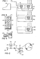
- FIG. 1 there is shown a system utilizing several printers according to the invention, 10, 10a and 10b coupled to an input terminal 12, such as, for example, a cathode ray tube input terminal, a teletype, or other input terminal.
- the printers 10, 10a and lOb according to the invention are designed so that several printers may be accessed from a single input terminal 12 to permit more efficient inputting of data into the printers by permitting data to be input into one of the printers while the other printers are in the process of printing.
- one of the printers such as, for example, the printer 10 is provided with a system control logic section 14 that communicates with the input terminal.12, the printers 10a and 10b as well as, for example, with a remotely located computer which can input data into any one of the printers 10, 10a or lOb via a line 15 and the system control logic 14.
- Each of the printers 10, 10a and 10b also contains a printer control logic section 16, 16a and 16b, respectively, which receives data from the system control logic 14 and converts the received data to control signals which operate the printing heads in the respective printers 10, 10a and 10b to generate characters in accordance with the data received from the input terminal 10 or from external sources such as via the line 15.
- Each of the printers 10, lOa and 10b also includes a printing mechanism generally designated by the reference numeral 18 which comprises a printing head 20 that is supported above a sheet stock medium 22 by.a pair of guides 24 and 26.
- the sheet stock medium is a relatively heavy paper web suitable for being fabricated into merchandise tags; however, the system may be used to print onto various forms of sheet stock, including adhesive backed stock, check printing stock or ordinary paper.
- the sheet stock, or web is contained in a roll 23 which is supported at a point 25 and advanced through the printer by a motor 28 which drives an advancing wheel 30.
- a roller 32 maintains the web 22 in contact with the advancing wheel 30 to permit the advancing wheel 30 to advance the web through the printer.
- the motor 28 is a stepping motor; however, any suitable servo motor may be used-. However, if a motor other than a servo motor is used, some means must be provided to sense the position of the motor shaft in order to permit the motor shaft position to be accurately controlled.
- a position indicating wheel 27, such as a magnetic wheel or light chopping wheel, and a sensor 29, such as a light sensor or a magnetic shaft position sensor would be suitable to provide this function.
- a web position sensor 34 which may be, for example, an optical sensor, is used to sense the position of the web and to indicate to the printer control logic that the web is in position for printing.
- a cutter 36 which is under the control of the printer control logic is used to cut the web after the web has been advanced a predetermined distance. If merchandise tag stock is being printed, the cutter 36 may be actuated each time the web is advanced a distance corresponding to the length of a single tag, or after the web has been advanced by a distance corresponding to the length of several tags, as desired.
- the print head 20 is a matrix type magnetically actuated wire printer head that has two columns of printing elements; however, any type of matrix print head having one or more columns of printing elements may be used.
- any type of matrix print head having one or more columns of printing elements may be used.
- the actual printing mechanism need not be mechanical or electromagnetic, and various printing mechanisms, such as thermal, ink spray or other printing mechanisms may be used.
- the printing head 20 utilizes nine printing elements 40 disposed in two columns designated as A and B for purposes of identification.
- each of the print elements 40 has a diameter of 0.014 inch, and the distance between the center lines of the print elements 40 in the columns A and B is 0.0138 inch.
- the vertical spacing between centers of adjacent print elements in column A and column B is 0.01175 inch.
- the printing head 20 is moved in a direction perpendicular to the columns A and B , and the print elements 40 are selectively actuated as the print head 20 is moved in order to generate imprints at predetermined locations on the web.
- the imprint is made by electrically actuating a solenoid 42 (FIG. 4) in order to cause the print element 40 to extend from the head 20 and to contact an inked or carbon ribbon disposed between the web and the element 40, thereby causing the inked or carbon ribbon to produce a mark having a diameter substantially equal to the diameter of the element 40 on the web.
- thermal, ink jet or other printing techniques may be used.
- the web In the event of thermal printing, the web would be fabricated from thermally sensitive material and the temperature of the print elements 40 would be raised whenever a mark is desired. In the case of ink jet printing, the element 40 would be replaced with nozzles which would squirt ink whenever a mark was desired.
- the printer according to the present invention is capable of printing characters of various sizes in various fonts in either one pass or two passes of the printing head.
- the printer in order to determine how the various characters are printed, it is necessary to understand the basic operation of the machine.
- the printer according to the invention generates all of its characters from a matrix whose coarseness or fineness is determined by the number of columns contained in the printing head and the number of passes required to form a character.
- a two-column printing head is employed, and characters are formed in either one or two passes; however, the device can be modified to utilize a head having more or less than two columns of elements and any number of printing passes.
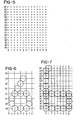
- FIG. 5 The matrix of possible print positions utilizing a two-column printing head and one or two printing passes is illustrated in FIG. 5.
- a vertical column is printed by first appropriately positioning one of the A or B columns over the area to be printed, energizing appropriate ones of the print elements in the column so positioned, stepping the head by an amount equal to the spacing between the A and B columns and energizing the other column to generate imprints between the imprints previously made in order to generate a vertical line from a series of overlapping dots.
- the sheet stock medium or web being printed is advanced by an amount equal to one-half the center-to-center vertical spacing between elements in the A and B columns of the print head, and a second pass, usually in the reverse direction, may be made to further fill in the vertical lines.
- FIG. 5 The matrix of possible print positions for a two-pass, two-column system is illustrated in FIG. 5.
- the print positions of the elements of column A during the first pass are designated as AO through A3, with the symbol A0 representing the bottom most element of column A and the designation A3 representing the upper most element of column A.
- the print positions of the elements of column B are designated as BO through B4.
- the horizontal print positions of the printing matrix are designated by the reference numerals 0 through 13.
- the designations AO' through A3' and the designations BO' through B4' indicate the print positions of the elements of the respective columns A and B during a second pass where the web of sheet stock has been advanced by a distance equal to one-half of the vertical center-to-center spacing of adjacent elements of column A and column B.
- the possible print positions of the elements during the second pass are at the same locations 0 through 13 that they were during the first pass.
- any given element cannot be fired successively along two adjacent horizontal possible print positions, but as a result of the mass of a print element, it can only be fired every other possible print position.
- the gap between horizontal imprints left during a first pass can be filled in during the second pass.
- the matrix of FIG. 5 illustrates the maximum size of a standard character.
- a standard character normally fills up the vertical possible print positions between BO and B4' and the horizontal possible print positions between 0 and 8.
- the horizontal possible print positions 9 through 13 are normally left for intercharacter spacing; however, characters smaller or larger than a standard character may occupy a greater or smaller number of horizontal possible print positions, and thus, vary the intercharacter spacing accordingly.
- a typical single-pass character is the numeral "6" (FIG. 6) which happens to be a reduced size character that does not occupy the entire matrix of possible print positions.
- each of the elements forming the character is positioned along the vertical possible print positions A0 through A2 and BO through B3, and no vertical possible print position corresponding to primed, or second pass positions, are required.
- FIG. 6 can be generated in a single pass. It is also to be noted that although a reduced size numeral "6" has been illustrated, a single-pass numeral “6" having a standard character size that occupies the entire matrix of possible print positions may also be generated. A reduced size numeral "6" is illustrated in FIG. 6 to indicate that various size characters can readily be printed on the same line in a single pass.
- OCR optical character recognition
- Such characters can readily be generated utilizing a two-pass technique wherein gaps or spaces left during the first pass can be filled in during the second pass.
- An example of a typical character than can be generated in two passes is the OCR character "6" illustrated in FIG. 7.
- the web of sheet stock is advanced one-half step to the primed position after the completion of the first printing pass in order to permit the print positions AO through A3' and BO' through B3' to be printed at the horizontal position 0, and to permit the positions BO' through Bl'. and AO' to be printed at the horizontal position 8.
- This "staircase effect" can be minimized by increasing the number of possible horizontal and vertical print positions, however, this is not practical since it greatly increases the complexity of the printer and reduces printing speed because either more passes are required, or the speed of the head must be reduced to permit a particular printing element to be fired more often within a given distance along the path of travel.
- each element forming a print character is defined not only by the horizontal and vertical possible print positions it is to occupy, but also by a time delay term.
- a particular print element need not be fired immediately when a given print position is reached, but rather, the firing may be delayed by a predetermined time interval selected to permit the head to move a predetermined distance prior to actuating the printing element.
- each element forming the character need not be positioned exactly at a possible element location, but may be offset by a distance determined by the rate at which the printing head travels across the web of sheet stock medium and the time delay defining the position of the element.
- FIG. 9 shows a substantially straight diagonal line in the numeric "N" rather than the "stairstep" diagonal illustrated in FIG. 8.
- the printer according to the present invention can also be utilized to print characters that are larger than the size of a standard character. This is done by utilizing two passes to print the large size characters. During the first pass, the lower (or upper) half of the large size character is printed. The web of sheet stock is then advanced by an amount equal to or less than the height of the enlarged character, and the other half of the enlarged character is printed during the second pass.
- the numeral. "2JI illustrated in FIG. 10 was printed by first printing the lower portion defined by the printing positions BO through B4 and A0 through A3, and then by advancing the web of sheet stock by twelve half steps (that is twelve times the distance it would have been advanced if a standard character were being printed in two passes as previously described) and printing the upper half of the numeral "2" in the print positions Al' through A3' and B2' through B4'.
- the printing elements corresponding to print positions AO' and BO' through Bl' were not used during this pass, but they could have been used to fill in gaps between print positions B3 and B4, or alternatively, the web of sheet stock medium could have been advanced up to sixteen half steps to provide a character twice as large as a standard character, rather than the one and three-quarter size character illustrated in FIG. 10.
- the position of each printed element is defined not only by a possible print position, but also by a time delay. This is illustrated by the relatively straight diagonal line in the numeral "2" of FIG. 10, and also from the fact that many of the various printed elements do not lie on a possible print position, but rather are displaced therefrom by a distance corresponding to the programmed delay.
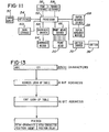
- Data is input into the printer according to the invention by a data input terminal 12 (FIG. 11) which, as previously stated, may be a cathode ray tube data input terminal, such as the terminal 12 of FIG. 1, another computer, or simply a keyboard.
- the output signal of the data input 50 may be in the form of ASCII characters, which are applied to a processor 52 within the printer via an interface 54.
- the function of the processor 52 is to receive the ASCII data from the data input terminal 50 and to convert it to a form suitable for driving the print head, the carriage and the paper advance drivers in order to generate the appropriate characters on appropriate positions on the web being printed.
- the processor 52 combines the functions of the system control logic 14 and printer control logic 16 of FIG. 1, it is illustrated as a single block for purposes of simplicity.
- the system stores three types of information.
- the information that is stored includes information defining the various fonts, which is stored in a font storage location 56; data defining the format in which a particular tag or label is to be printed, which is stored in the format storage location 58; and data defining which alpha-numeric characters are to be printed, which is stored in a format storage location 60.
- the data stored in the font storage is preprogrammed and generally cannot be changed by data input from the data input 50.
- the data input from the data input 50 merely selects which character is to be printed.
- the format storage locations 58 are programmable by data input from the data input 50 and used to define the field in which the characters are to be printed.
- the data entered in the format storage defines the skeleton or the outline of the tag to be printed and includes such information as the font of each character, check digits which may be printed, whether or not the line of characters have a fixed length, whether certain characters are always printed, the location on the merchandise tag where the characters are to be printed, the length and width of each tag, the number of tags to be printed, and the number of tags to be printed between cuts.
- the data stored in the data storage 60 stores data representative of the particular characters to be printed on a tag. This data is used in conjunction with the format storage data and the font storage data, and printing is controlled by selecting a particular format from the format storage data 58.
- the processor 52 then inserts the data from the data storage 60 in the appropriate places defined by the format storage 58 and prints the data in the appropriate font selected by the format storage 58 from the font storage 56.
- the processor 52 then converts the data stored in the data storage 60, the format storage 58 and the font storage 56 to signals that actually control the printing. These signals take the form of carriage control signals which are amplified by a carriage driver 62 which in turn actuate a carriage motor 64 which determines the position of the print head.
- a print head driver 66 receives signals from the print head driver 66 and uses selectively to actuate the various pins of the print head 20.
- a paper advance driver 68 amplifies signals from the processor 52 and controls the position of the paper advance motor 28.
- a cutter driver 70 amplifies signals from the processor 52 and causes the cutter 36 to be activated at predetermined intervals.
- FIG. 12 shows the system illustrated in FIG. 11, particularly the processor 52, in greater detail.
- the processor 52 includes program storage locations which control the flow of information between the data storage 60, the font storage 56 and the format storage 58 via a communications' interface 74.
- the processor 52 also includes cutter controls 69 which actuate the cutter driver 70, carriage controls 76 which cooperate with a step generator 78, carriage driver controls 80, a step character counter 82 and a line step counter 84 to actuate the carriage driver 62 to thereby control the motor 64.
- paper advance controls 86 cooperate with paper advance driver controls 88, a step generator 90, a half-step counter 92 and a twleve-step counter 94 to control paper advance driver 68.
- a set of printing head controls 96 selectively operate various ones of the print head drivers 66 to activate the various pins in the print head 20 at appropriate times.
- both the carriage motor 64 and the paper advance motor 28 are stepping motors having a plurality of sequentially operable field coils which cause the shaft of the motor to be incremented a predetermined increment each time different windings are successively energized.
- the speed of the motors 64 and 28 is determined by the respective step generators 78 and 90 which in turn control the carriage driver controls and the paper advance driver controls 80 and 88 to cause different ones of the windings of the motors 64 and 28 to be energized each time a new step is generated by one.of the step generators 78 or 90.
- the various counters including the character step counter 82, the line step counter 84, the half-step counter 92 and the twelve-step counter 94 serve to provide indications of the positions of the carriage and also the position of the stock being printed.
- the character step counter 82 serves to indicate where the carriage is positioned with respect to a particular character being printed
- the line step counter serves to indicate the position of the head along a particular line being printed.
- the half-step counter 92 is used to indicate when the stock has been advanced a half step so that the second printing pass, which fills in gaps left by the first printing pass, may begin.
- the twelve-step counter is used to determine when the stock has been advanced sufficiently to permit the second pass in the printing of an oversized character to be initiated.
- data is input into the system from the data input 50.
- This data may be either format data, defining the field on which characters are to be placed, or may be data representative of the characters themselves. If the data being input is format representative data, that data is routed to the format storage 58 by the communications' interface 74, which is simply a series of electronic switches that route the data to appropriate locations. Similarly, data defining the characters that are to be printed is routed to the data storage 60.
- the format storage 58 is capable of holding several formats, with the actual number of formats being determined- by their complexity. This permits the operator first to store several formats, and then to select a particular one of the formats stored and to enter data to be printed in accordance with that format. Thus, it is not necessary to enter new format data each time new character data is to be entered. The operator simply selects one of the stored formats stored in the format storage 58, enters the character data and initiates the printing cycle. In the present embodiment, the operator may transmit data to any one or more of up to seven printers.
- the paper advance controls 86 cause the step generator 90 to generate steps to thereby cause the paper advance driver controls 88 and the paper advance driver 68 to cause the motor 28 to advance the web of sheet stock to the printing position.
- the web. position sensor 34 senses the position of the web and applies the web position information, which may be information indicative of the position of the end of the web, or of the detection of a hole, slit or other index on the web, and applies this information to the paper advance controls 86.
- the paper advance controls utilize this information as well as information from the format storage 58 to advance the web 22 to a line position on which the first character is to be printed. Once this position is reached, the paper advance controls cause the step generator 90 to cease generating steps, thereby maintaining the motor 28 stationary.
- the carriage controls 76 cause the step generators 78 to generate steps that cause the carriage driver controls 80 and the carriage driver 62 to drive the motor 64 to a position corresponding to a beginning of a line position of the print head 20.
- the carriage controls cause the step generator 78 to generate steps at a gradually increasing rate to accelerate the head to printing speed.
- the line step counter 84 counts the number of steps generated by the step generator 78 (or wheel 27, FIG. 2) to provide an indication of the position of the printing head 20 along the print line.
- the printing head controls 96 cause the print head driver 66 to activate the printing elements on the print head 20 in the particular sequence necessary to generate the character to be printed.
- the sequence information is determined by which character is to be printed, as determined by data stored in the data storage 60, and by the particular font of the character to be printed, as stored in the font storage 56.
- the data storage 60 selects a particular character to be printed, and the format storage 58 determines which font is to be printed, and the information defining the sequence of actuation of the printing element of the printing head 20 is retrieved from the font storage 56 in accordance with the character defined in the data storage 60 and the font defined by the format storage 58.
- the data defining each character of each font is stored in the font storage 56 as a combination of carriage position data, which indicates.the approximate carriage position at which particular printing elements of the print head 20 are to be actuated, and time delay data which indicates a time delay interval between the time that the defined carriage position is reached and the actual time that the various print elements are fired.
- the carriage position data stored in the,font storage 56 is representative of intracharacter position, or the position of the printing head 20 with respect to the particular character being printed.
- the character step counter 82 is reset at each new character position, and counts from zero through a count corresponding to the distance between the beginning of adjacent character spaces, for example, in the present embodiment, a count from zero through thirteen.
- the count in the character step counter 82 determines the position of the print head 20 with respect to the character being printed and is compared with the printing head position data stored in the font storage to control the firing of the elements 40 in the head 20. For example, if the count in the character step counter 82 is zero and the count in the line step counter 84 corresponds to data in the data storage 60 indicating that the letter "N" is to be printed at that position, and if the font selected corresponded to the font of the letter "U” illustrated in FIG. 9, the printing head controls would cause the printing elements corresponding to elements A0, Al, A2 and A3 to be energized in order to place imprints on the medium at the zero position in FIG. 9.
- the printing elements B0, Bl, B2 and B3 are actuated when the count in the character step counter 82 indicated that the printing head 20 has moved a sufficient distance so that the B column of elements in the head 20 are positioned over the imprints previously printed by the A column of the print head 20.
- the spacing between the A and B columns on the print head 20 corresponds essentially to two steps of the character step counter 82.
- the appropriate elements in the A column are actuated when a count of zero is present in the character step counter 82, and the appropriate printing elements in the B column are actuated when the count in the character step counter reaches two.
- the line located at the zero position of the character "N" of FIG. 9 is substantially vertical, there is no need to program any time delays into the data stored in the font storage 56 defining the vertical portion of the letter "N" at the print position zero.
- the diagonal line extending between print positions one and seven does not lie along a diagonal intersecting the various print positions between one and seven, and thus, a time delay factor must be stored.
- Those imprints along the diagonal requiring a time delay factor are illustrated in dashed lines, and it can be seen that the centers of the imprints indicated by dashed lines do not lie along any of the defined possible print positions.
- the distance between the actual center of the various imprints and the defined print positions corresponds to the distance travelled by the print head 20 during the delay time interval stored in the font storage 56.
- the offset of each imprint from a defined print position is determined by the stored delay for each offset imprint stored in the font storage 56.
- a comparator 98 within the printing head controls compares the count in the character step counter 82 with carriage position data stored in the font storage 56. Whenever the count in the character step counter 82 corresponds to data in the font storage 56 indicating that one or more particular print elements are to be fired, the comparator 98 indicates to the printing head controls 96 which printing elements are to be actuated. The time delay data stored in the font storage 56 for each of the print elements to be actuated is then examined. If there is no delay stored within the font storage 56 for the actuation of a particular printing element, then that printing element is fired immediately, or within a minimum response time of the system, after the count in the character step counter corresponds to the data stored in the font storage 56.
- variable delay 100 is utilized to program the delay of a variable delay 100 within the printing control head 96.
- the output of a comparator 98 triggers the variable delay 100 whenever the print head position data stored in the font storage 56 corresponds to a count in the character step counter 82, and the variable delay 100 actuates the appropriate element in the print head 20 via the print head driver 66 after a time interval corresponding to the delay data stored in the font storage 56 has elapsed.
- the sequence of the comparator 98 triggering the variable delay 100 is utilized even when no delay term is stored for a particular actuation of a particular printing element stored within the font storage 56.
- the delay provided by the variable delay 100 is set to zero, or as near to zero as is practicable.
- the delay provided by the variable delay 100 cannot be practically reduced to zero, and it is this delay that was referred to as the system delay above in connection with the discussion of the actuation of printing elements when no delay term is stored in the font storage 56.
- the head After the first pass in the printing of the character "N", such as the character "N" illustrated in FIG. 9, or any other character being printed, has been completed, the head continues along the print line being printed, until the end is reached.
- the end of the print is indicated by an end-of-line indicator 102 which indicates to the carriage control 76 that the end of the line has been reached.
- a similar beginning of line indicator 103 is used to indicate the beginning of a line. When this occurs, the rate at which the step generator 78 generates steps is gradually reduced in order to bring the print head 20 to a stop.
- a signal is applied from the carriage control 70 to the carriage driver controls 80 via a line 104 indicating that the direction of the motor 64 is to be reversed.
- the carriage driver controls 80 to reverse the sequence of the energization of the field windings within the motor 64 to cause the motor 64 to rotate in the opposite direction.
- the step generator 78 is then caused to again generate steps at a gradually increasing rate to cause the printing head 20 to be accelerated in the reverse direction.
- the web 22 is advanced by an appropriate amount to permit the second pass to be printed.
- the web 22 is advanced by an amount equal to essentially one-half the vertical distance between the centers of the printing elements in a given column. This distance is determined by the half-step counter 92, and causes the web 22 to be advanced by an amount sufficient to cause imprints made on the web during the second pass to overlap the imprints made by elements of the same column on the first pass.
- the line step counter 84 is decremented and the count therein is compared with the data stored in the data storage 60 and the format stored in the format storage 58 to determine when and where a particular character is to be printed. Whenever a particular character to be printed is identified, the count in the character step counter 82 is increased to its maximum count of thirteen, and the count gradually decremented to zero as the reverse printing of that character takes place.
- the location of each imprint is controlled by storing position location data and delay time data in the font storage 56; however, the time delay data stored in the font storage 56 for printing in the reverse pass defining a particular print location is different from the data defining the same print position in the forward pass since printing is now occurring in the reverse direction, and the B column precedes the A column, rather than vice versa as in the forward pass.
- the delay data need only be modified by a constant relating to the distance between the A and B columns, and by the time required by the print elements to actually make an imprint after being actuated (flight time).
- the reverse printing direction print positions are indicated by the positions BO' through B3' and AO' through A3'.
- the imprints made during the second pass substantially overlap the imprints made during the first pass to form a substantially straight, solid line.
- the printer continues to print in both directions until all of the entered data is printed in accordance with the appropriate format. After this occurs, and assuming that more than one tag is to be printed, the web 22 is again advanced to the next printing position, and if it is desired to produce individual tags, the cutter 36 (FIG.
- the printer may be utilized to print individual tags, a complete roll of attached tags, or groups of tags having any number of attached tags.
- the web advance is controlled by the twelve-step counter 94, which causes the web 22 to be advanced, for example twelve steps, to permit an oversize character, such as the character "2" of FIG. 10, to be printed.
- the imprints made on the second pass All through A3' and B2' through B4', are printed above the imprints BO through B4 and A0 through A3 made on the first pass, rather than overlapping them.
- the location of each imprint is defined by a print position term as well as a delay term. This is evident from the fact that not all of the imprints, particularly along the diagonal of the figure "2", lie directly on a defined print position, but are offset therefrom by a term related to the time delay.
- the data entered by the data input 50 (FIG. 12) or the input terminal 12 (FIG. 1) is not directly compatible with the printer logic, but has typically a standard data format, such as ASCII.
- ASCII standard data format
- the data entered into the printer must first be converted to a format usable by the printer before printing can occur. This is accomplished by a series of look-up tables as illustrated in FIG. 13.
- the ASCII data representing each character is received and applied to an address look-up table that generates different eight-bit address for each of the ASCII characters received.
- the address look-up table that generates different eight-bit address for each of the ASCII characters received.
- the particular font in which that character is to be printed is determined from the data stored in the format storage 58 (FIG. 12) and applied to a font look-up table (FIG. 13) within the font storage 56 (FIG. 12).
- the font look-up table then generates a 16-bit.address indicating where the data defining the particular character to be printed in the selected font may be found in the font storage 56.
- the 16-bit address from the font look-up table addresses the data in the font storage 56 which defines the particular character to be printed.
- the data defining the character is provided in two bytes in the format illustrated in FIG. 13.
- This format begins with a link bit, typically a one which indicates that additional frames of data follow. This link bit is followed by some unused data positions, which are in turn followed by pin data which gives the frame pin pattern or which of the pins are to be fired in order to form the character. In the subsequent byte, data representative of the intracharacter position count is provided.
- the printer is able to monitor the count provided by the character step counter 82 (FIG. 12) with the data provided in FIG. 13 by comparing the count in the character step counter 18 with the stored intracharacter position count.
- the pin data is examined to determine which pins or printing elements are to be actuated at that nominal intracharacter position, and the intracharacter position delay data is examined to determine the actuation time delay for each pin.
- the distance between adjacent possible print positions is divided by sixteen, and the intracharacter position delay is stored as a number representative of the number of sixteenths of the distance between adjacent print positions that the center of the imprint is to be offset from the last possible print position.
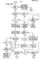
- FIGS. 14-17 The steps by which the printer processes received data are illustrated in FIGS. 14-17.
- the line pointer is initialized to starting position and the printer status is set to ready to enable the printer to receive a new transmission.
- the data received is repeatedly checked to determine whether the data being received is indeed a new transmission, or the continuation of another transmission, possibly meant for another printer, or noise. This determination is made by checking for a start of transmission code.
- a start of transmission code indicating a new transmission
- the fast font flag has been set, a determination is made if the bold flag had been set by previously-received data. The purpose of making this determination is that if single-pass font data is presently being received and if the bold font flag had been previously set, even though single-pass font data is being received, the previous setting of the bold flag indicates that the line to be printed contains bold font in addition to the single-pass font, and thus two printing passes must be made even though the data currently being received is single-font data. Similarly, if bold pass font is currently being received, the double-pass flag must be set even though the previous data was single-pass data.
- the bold flag is set to indicate to the printer that the web must be advanced a sufficient amount between passes to permit the oversize font to be printed.
- the double-pass flag simply indicates that two passes will be necessary to print that particular line.
- the stored line data and the batch control pointer data are then examined for the presence of an end of text, ETX, character, normally present at the end of the control data which follows the character data. If no end of text character is received, the printer is set to receive another transmission. If an end of text character has been received, the printer is conditioned to process the data for printing.
- ETX end of text
- the pointer indicating the present line is temporarily stored (FIG. 15) and a beginning line flag is set.
- the value of the present line pointer is set only in temporary storage because at this point it is not known whether the data represents data in the forward printing direction or in the reverse printing direction.
- the pointer is then backed to the beginning of the line, which is done by looking for the carriage return of the previous line and incrementing the pointer one space after the previous carriage return.
- the data is then converted from ASCII, or from whatever form the data was received, and loaded into a batch buffer and the pointer incremented.
- the line is then examined by determining the physical position of the head to determine whether it is a single- or double-pass line.
- the print head travel must begin in the forward direction. If it is a single-pass line, and the print head is set to travel in the reverse direction, the web is advanced to the next line position. Data is loaded temporarily as a new pointer and the pointer is decremented to indicate that the loading of the data should begin just ahead of the carriage return, CR, rather than just after it.
- the next character is then loaded and examined to determine whether it is a double-pass type of font, such as, for example, optical character recognition or oversize font, or whether it is a single-pass, high-speed font. If it is a standard size, double-pass font, such as OCR, the OCR offset, which controls the horizontal centering of the character is loaded and the font is set to double pass.
- the character is an oversize or bold character
- the bold offset is loaded and the font is again set to double pass.
- the character is a standard- size, high-speed or single-pass character
- the high-speed offset is loaded and the font is set to single pass.
- the character is a double-pass font type
- the proper beginning printing direction must be set up. The setting up of the proper beginning printing direction is illustrated in FIG. 16.
- the font of the present character is first examined to determine if it is a double-pass type font. If it is not, the data is examined to determine whether this character is the first character of the line of data to be printed. If not, the proper printing direction has already been set up in the beginning line and the next character may simply be loaded.
- the font type of the present character is a double-pass font
- the data is checked to determine whether it is beginning line data. If it is, and if the carriage is going in the forward direction, the carriage is simply ramped up. Otherwise, it is returned to the home position prior to being ramped up as previously described. If the data is not beginning line data, a determination is made to see whether the print direction is forward or reverse, and the line pointer is incremented or decremented accordingly, and the next character loaded.
- the font is none of the three fonts previously discussed, a check is made to see if it is a reduced size or small font (FIG. 17). If it is, the appropriate small font is loaded and the single-pass font flag set, and the data is processed in a similar manner to the processing of the high-speed font. If it is not a small font, a count of the data is made to determine whether there is zero data representative of the end of the line in the reverse direction. If is is a zero, the travel of the printing head is ramped. Determination is made whether or not additional lines of print are required. If not, the tag or label is cut as necessary and printing stopped if the batch is finished.
Abstract
Description
- This invention relates generally to printers, and more particularly to a high quality printer that utilizes a plurality of matrix elements for producing high quality characters in various fonts.
- Matrix printers are known, and typical matrix printers according to the prior art are disclosed in United States Patents Nos. 4,159,882; 3,882,988; 3,942,620; and 3,900,094.
- While the devices disclosed in the above patents provide a way to achieve matrix printing of reasonable quality, they do not provide the flexibility of positioning of the matrix elements provided by the apparatus according to the present invention.
- Accordingly, it is an object of the present invention to provide an improved matrix printer that overcomes many of the disadvantages of the prior art matrix printers.
- It is another object of the present invention to provide a matrix printer that provides great accuracy in the positioning of the printing elements to permit high quality characters of various fonts to be produced.
- It is yet another object of the present invention to provide a matrix printer that provides greater flexibility in the positioning of the various elements forming the printed characters than has heretofore been achieved.
- It is yet another object of the invention to provide a matrix printer capable of printing characters of various sizes.
- It is yet another object of the present invention to provide a printer capable of printing a line of characters in a single pass.
- It is still another object of the present invention to provide a matrix printer capable of printing a line of high quality characters in two passes in opposite directions.
- It is still another object of the present invention to provide a matrix printer capable of intermixing characters of the type that can be printed in a single pass with characters of the type that require two passes on the same line.
- It is yet another object of the present invention to provide a matrix printer capable of printing characters with overlapping print elements in both the horizontal and vertical direction in two passes per line, and for printing other characters in a single pass per line.
- It is yet another object of the present invention to provide a matrix printer capable of printing both in the forward and reverse direction.
- In accordance with an important aspect of the present invention; data defining each character of each font to be printed is stored in two components. The first of these components is the nominal position of the print head at which each of the print elements is to be fired to form a particular character. The second component is a time delay component which defines a time delay between the time that a nominal position is reached and the time that the imprinting element is fired. Thus, the print head position data provides a coarse definition of the shape of a character, and the time delay data provides accurate positioning of each printed element to define the fine features of the character.
- These and other objects and advantages of the present invention will become readily apparent upon consideration of the following detailed description and attached drawing, wherein:
- FIG. 1 is a block diagram illustrating a typical printer system utilizing printers according to the present invention;
- FIG. 2 is a diagram representative of the printing head and sheet stock medium advancing mechanism;
- FIG. 3 is a front view of the printing head illustrating the positions of the printing elements forming the array;
- FIG. 4 is a side view, partially in cross section, of one of the printing elements illustrated in IFG. 3;
- FIG. 5 is a diagram illustrating all of the possible print positions that may be used to define a character;
- FIGS. 6-10 are illustrations of various characters that may be printed by the printing system according to the invention;
- FIG. 11 is a functional block diagram of the control system employed in the printer according to the invention;
- FIG. 12 is a functional block diagram similar to FIG. 11 illustrating the functional elements of the control system of the printer according to the present invention in greater detail;
- FIG. 13 is a diagram illustrating the format in which the data defining each character is entered and stored; and
- FIGS. 14-17 are functional flow charts illustrating the logical operation of the control circuitry of the printer according to the invention.
- Referring now to the drawing, with particular attention to FIG. 1, there is shown a system utilizing several printers according to the invention, 10, 10a and 10b coupled to an
input terminal 12, such as, for example, a cathode ray tube input terminal, a teletype, or other input terminal. Theprinters single input terminal 12 to permit more efficient inputting of data into the printers by permitting data to be input into one of the printers while the other printers are in the process of printing. - In order to permit several printers to be coupled to a single input terminal, one of the printers, such as, for example, the
printer 10 is provided with a system control logic section 14 that communicates with the input terminal.12, theprinters 10a and 10b as well as, for example, with a remotely located computer which can input data into any one of theprinters printers control logic section respective printers input terminal 10 or from external sources such as via the line 15. Since, in the system according to the invention, only a single system control logic section 14 is required to control the operation of several printers, theprinters 10a and 10b are not provided with such a system control logic section. Such an arrangement is advantageous since it results in a significant reduction in cost and complexity because additional printers added to the system need not have the system control logic section 14. - Each of the
printers 10, lOa and 10b also includes a printing mechanism generally designated by thereference numeral 18 which comprises aprinting head 20 that is supported above asheet stock medium 22 by.a pair ofguides roll 23 which is supported at apoint 25 and advanced through the printer by amotor 28 which drives an advancingwheel 30. Aroller 32 maintains theweb 22 in contact with the advancingwheel 30 to permit the advancingwheel 30 to advance the web through the printer. In the embodiment shown, themotor 28 is a stepping motor; however, any suitable servo motor may be used-. However, if a motor other than a servo motor is used, some means must be provided to sense the position of the motor shaft in order to permit the motor shaft position to be accurately controlled. Aposition indicating wheel 27, such as a magnetic wheel or light chopping wheel, and asensor 29, such as a light sensor or a magnetic shaft position sensor would be suitable to provide this function. Aweb position sensor 34, which may be, for example, an optical sensor, is used to sense the position of the web and to indicate to the printer control logic that the web is in position for printing. Acutter 36, which is under the control of the printer control logic is used to cut the web after the web has been advanced a predetermined distance. If merchandise tag stock is being printed, thecutter 36 may be actuated each time the web is advanced a distance corresponding to the length of a single tag, or after the web has been advanced by a distance corresponding to the length of several tags, as desired. - In the embodiment illustrated in the drawing, the
print head 20 is a matrix type magnetically actuated wire printer head that has two columns of printing elements; however, any type of matrix print head having one or more columns of printing elements may be used. In addition, although a magnetically actuated wire printing head is illustrated, the actual printing mechanism need not be mechanical or electromagnetic, and various printing mechanisms, such as thermal, ink spray or other printing mechanisms may be used. - In the embodiment illustrated in FIG. 3, the
printing head 20 utilizes nineprinting elements 40 disposed in two columns designated as A and B for purposes of identification. In the embodiment shown, each of theprint elements 40 has a diameter of 0.014 inch, and the distance between the center lines of theprint elements 40 in the columns A and B is 0.0138 inch. The vertical spacing between centers of adjacent print elements in column A and column B is 0.01175 inch. Thus, since the vertical spacing between theelements 40 in column A and column B is less than the diameter of the print elements, a mark printed by an element in column A will overlap a mark printed by an adjacent element in column B. - During operation of the printer, the
printing head 20 is moved in a direction perpendicular to the columns A and B, and theprint elements 40 are selectively actuated as theprint head 20 is moved in order to generate imprints at predetermined locations on the web. In the present embodiment, the imprint is made by electrically actuating a solenoid 42 (FIG. 4) in order to cause theprint element 40 to extend from thehead 20 and to contact an inked or carbon ribbon disposed between the web and theelement 40, thereby causing the inked or carbon ribbon to produce a mark having a diameter substantially equal to the diameter of theelement 40 on the web. However, as previously stated, thermal, ink jet or other printing techniques may be used. In the event of thermal printing, the web would be fabricated from thermally sensitive material and the temperature of theprint elements 40 would be raised whenever a mark is desired. In the case of ink jet printing, theelement 40 would be replaced with nozzles which would squirt ink whenever a mark was desired. - As was previously stated, the printer according to the present invention is capable of printing characters of various sizes in various fonts in either one pass or two passes of the printing head. However, in order to determine how the various characters are printed, it is necessary to understand the basic operation of the machine.
- The printer according to the invention generates all of its characters from a matrix whose coarseness or fineness is determined by the number of columns contained in the printing head and the number of passes required to form a character. In the illustrated embodiment, a two-column printing head is employed, and characters are formed in either one or two passes; however, the device can be modified to utilize a head having more or less than two columns of elements and any number of printing passes.
- The matrix of possible print positions utilizing a two-column printing head and one or two printing passes is illustrated in FIG. 5. In the matrix illustrated in FIG. 5, a vertical column is printed by first appropriately positioning one of the A or B columns over the area to be printed, energizing appropriate ones of the print elements in the column so positioned, stepping the head by an amount equal to the spacing between the A and B columns and energizing the other column to generate imprints between the imprints previously made in order to generate a vertical line from a series of overlapping dots. If further resolution is required, the sheet stock medium or web being printed is advanced by an amount equal to one-half the center-to-center vertical spacing between elements in the A and B columns of the print head, and a second pass, usually in the reverse direction, may be made to further fill in the vertical lines.
- The matrix of possible print positions for a two-pass, two-column system is illustrated in FIG. 5. In the illustration of FIG. 5, the print positions of the elements of column A during the first pass are designated as AO through A3, with the symbol A0 representing the bottom most element of column A and the designation A3 representing the upper most element of column A. Similarly, the print positions of the elements of column B are designated as BO through B4.
- The horizontal print positions of the printing matrix are designated by the
reference numerals 0 through 13. The designations AO' through A3' and the designations BO' through B4' indicate the print positions of the elements of the respective columns A and B during a second pass where the web of sheet stock has been advanced by a distance equal to one-half of the vertical center-to-center spacing of adjacent elements of column A and column B. The possible print positions of the elements during the second pass are at thesame locations 0 through 13 that they were during the first pass. However, during any single pass, any given element cannot be fired successively along two adjacent horizontal possible print positions, but as a result of the mass of a print element, it can only be fired every other possible print position. Thus, if fine resolution in the horizontal direction is necessary, the gap between horizontal imprints left during a first pass can be filled in during the second pass. - The matrix of FIG. 5 illustrates the maximum size of a standard character. Such a standard character normally fills up the vertical possible print positions between BO and B4' and the horizontal possible print positions between 0 and 8. The horizontal
possible print positions 9 through 13 are normally left for intercharacter spacing; however, characters smaller or larger than a standard character may occupy a greater or smaller number of horizontal possible print positions, and thus, vary the intercharacter spacing accordingly. - As previously stated, the printer according to the invention is capable of printing both single-pass and double-pass characters. A typical single-pass character is the numeral "6" (FIG. 6) which happens to be a reduced size character that does not occupy the entire matrix of possible print positions. In the character illustrated in FIG. 6, each of the elements forming the character is positioned along the vertical possible print positions A0 through A2 and BO through B3, and no vertical possible print position corresponding to primed, or second pass positions, are required. In addition, it is not necessary to actuate any print elements during adjacent horizontal possible print positions. The most rapid actuation occurs at vertical positions BO and Al where the elements are acuated at every other horizontal print position, namely
horizontal positions - Often, it is necessary to generate characters with a greater resolution than can be generated with a single pass, such as in the case of optical character recognition, or OCR, characters. Such characters can readily be generated utilizing a two-pass technique wherein gaps or spaces left during the first pass can be filled in during the second pass. An example of a typical character than can be generated in two passes is the OCR character "6" illustrated in FIG. 7. In the example illustrated in FIG. 7, the web of sheet stock is advanced one-half step to the primed position after the completion of the first printing pass in order to permit the print positions AO through A3' and BO' through B3' to be printed at the
horizontal position 0, and to permit the positions BO' through Bl'. and AO' to be printed at thehorizontal position 8. This fill-in during the second pass improves the definition of the four corners forming the bottom loop of the six. It should be noted that although the OCR numeral "6" illustrated in FIG. 7 is a standard size character, two-pass printing can also be utilized to improve the definition of characters smaller than the standard size. - Although two-pass printing greatly enhances the definition of many characters, characters having diagonal lines provide a particular problem for systems like the present system having discrete possible printing positions arranged in a matrix of horizontal rows and vertical columns. This is because diagonal lines produce a pronounced "staircase effect" when the angle of the diagonal line being printed is not the same as the angle between adjacent, diagonally offset, print positions. Such a staircase effect is illustrated in the diagonal line of the numeric "N" illustrated in FIG. 8. This "staircase effect" can be minimized by increasing the number of possible horizontal and vertical print positions, however, this is not practical since it greatly increases the complexity of the printer and reduces printing speed because either more passes are required, or the speed of the head must be reduced to permit a particular printing element to be fired more often within a given distance along the path of travel.
- Therefore, in accordance with an important aspect of the present invention, the position of each element forming a print character is defined not only by the horizontal and vertical possible print positions it is to occupy, but also by a time delay term. Thus, in the system according to the present invention, a particular print element need not be fired immediately when a given print position is reached, but rather, the firing may be delayed by a predetermined time interval selected to permit the head to move a predetermined distance prior to actuating the printing element. Thus, each element forming the character need not be positioned exactly at a possible element location, but may be offset by a distance determined by the rate at which the printing head travels across the web of sheet stock medium and the time delay defining the position of the element. The improvement in definition of the character is readily apparent with reference to FIG. 9, which shows a substantially straight diagonal line in the numeric "N" rather than the "stairstep" diagonal illustrated in FIG. 8.
- The printer according to the present invention can also be utilized to print characters that are larger than the size of a standard character. This is done by utilizing two passes to print the large size characters. During the first pass, the lower (or upper) half of the large size character is printed. The web of sheet stock is then advanced by an amount equal to or less than the height of the enlarged character, and the other half of the enlarged character is printed during the second pass.
- For example, the numeral. "2JI illustrated in FIG. 10 was printed by first printing the lower portion defined by the printing positions BO through B4 and A0 through A3, and then by advancing the web of sheet stock by twelve half steps (that is twelve times the distance it would have been advanced if a standard character were being printed in two passes as previously described) and printing the upper half of the numeral "2" in the print positions Al' through A3' and B2' through B4'. The printing elements corresponding to print positions AO' and BO' through Bl' were not used during this pass, but they could have been used to fill in gaps between print positions B3 and B4, or alternatively, the web of sheet stock medium could have been advanced up to sixteen half steps to provide a character twice as large as a standard character, rather than the one and three-quarter size character illustrated in FIG. 10. It should be noted that, even in the case of large characters, such as the one illustrated in FIG. 10, the position of each printed element is defined not only by a possible print position, but also by a time delay. This is illustrated by the relatively straight diagonal line in the numeral "2" of FIG. 10, and also from the fact that many of the various printed elements do not lie on a possible print position, but rather are displaced therefrom by a distance corresponding to the programmed delay.
- Data is input into the printer according to the invention by a data input terminal 12 (FIG. 11) which, as previously stated, may be a cathode ray tube data input terminal, such as the
terminal 12 of FIG. 1, another computer, or simply a keyboard. The output signal of thedata input 50 may be in the form of ASCII characters, which are applied to aprocessor 52 within the printer via aninterface 54. The function of theprocessor 52 is to receive the ASCII data from thedata input terminal 50 and to convert it to a form suitable for driving the print head, the carriage and the paper advance drivers in order to generate the appropriate characters on appropriate positions on the web being printed. Thus, although theprocessor 52 combines the functions of the system control logic 14 andprinter control logic 16 of FIG. 1, it is illustrated as a single block for purposes of simplicity. - The system according to the present invention stores three types of information. The information that is stored includes information defining the various fonts, which is stored in a
font storage location 56; data defining the format in which a particular tag or label is to be printed, which is stored in theformat storage location 58; and data defining which alpha-numeric characters are to be printed, which is stored in aformat storage location 60. In a typical system, the data stored in the font storage is preprogrammed and generally cannot be changed by data input from thedata input 50. The data input from thedata input 50 merely selects which character is to be printed. Theformat storage locations 58 are programmable by data input from thedata input 50 and used to define the field in which the characters are to be printed. The data entered in the format storage defines the skeleton or the outline of the tag to be printed and includes such information as the font of each character, check digits which may be printed, whether or not the line of characters have a fixed length, whether certain characters are always printed, the location on the merchandise tag where the characters are to be printed, the length and width of each tag, the number of tags to be printed, and the number of tags to be printed between cuts. - The data stored in the
data storage 60 stores data representative of the particular characters to be printed on a tag. This data is used in conjunction with the format storage data and the font storage data, and printing is controlled by selecting a particular format from theformat storage data 58. Theprocessor 52 then inserts the data from thedata storage 60 in the appropriate places defined by theformat storage 58 and prints the data in the appropriate font selected by theformat storage 58 from thefont storage 56. Theprocessor 52 then converts the data stored in thedata storage 60, theformat storage 58 and thefont storage 56 to signals that actually control the printing. These signals take the form of carriage control signals which are amplified by acarriage driver 62 which in turn actuate acarriage motor 64 which determines the position of the print head. Other signals which determine which pins of the print head to be fired or actuated are amplified by aprint head driver 66 and used selectively to actuate the various pins of theprint head 20. Similarly, apaper advance driver 68 amplifies signals from theprocessor 52 and controls the position of thepaper advance motor 28. Acutter driver 70 amplifies signals from theprocessor 52 and causes thecutter 36 to be activated at predetermined intervals. - FIG. 12 shows the system illustrated in FIG. 11, particularly the
processor 52, in greater detail. In the block diagram illustrated in FIG. 12, theprocessor 52 includes program storage locations which control the flow of information between thedata storage 60, thefont storage 56 and theformat storage 58 via a communications'interface 74. Theprocessor 52 also includes cutter controls 69 which actuate thecutter driver 70, carriage controls 76 which cooperate with astep generator 78, carriage driver controls 80, astep character counter 82 and a line step counter 84 to actuate thecarriage driver 62 to thereby control themotor 64. Similarly, paper advance controls 86 cooperate with paper advance driver controls 88, a step generator 90, a half-step counter 92 and a twleve-step counter 94 to controlpaper advance driver 68. A set of printing head controls 96 selectively operate various ones of theprint head drivers 66 to activate the various pins in theprint head 20 at appropriate times. - In the system according to the present invention, both the
carriage motor 64 and thepaper advance motor 28 are stepping motors having a plurality of sequentially operable field coils which cause the shaft of the motor to be incremented a predetermined increment each time different windings are successively energized. The speed of themotors respective step generators 78 and 90 which in turn control the carriage driver controls and the paper advance driver controls 80 and 88 to cause different ones of the windings of themotors step generators 78 or 90. The various counters, including thecharacter step counter 82, the line step counter 84, the half-step counter 92 and the twelve-step counter 94 serve to provide indications of the positions of the carriage and also the position of the stock being printed. Thecharacter step counter 82 serves to indicate where the carriage is positioned with respect to a particular character being printed, while the line step counter serves to indicate the position of the head along a particular line being printed. Similarly, the half-step counter 92 is used to indicate when the stock has been advanced a half step so that the second printing pass, which fills in gaps left by the first printing pass, may begin. The twelve-step counter is used to determine when the stock has been advanced sufficiently to permit the second pass in the printing of an oversized character to be initiated. - In operation, data is input into the system from the
data input 50. This data may be either format data, defining the field on which characters are to be placed, or may be data representative of the characters themselves. If the data being input is format representative data, that data is routed to theformat storage 58 by the communications'interface 74, which is simply a series of electronic switches that route the data to appropriate locations. Similarly, data defining the characters that are to be printed is routed to thedata storage 60. - The
format storage 58 is capable of holding several formats, with the actual number of formats being determined- by their complexity. This permits the operator first to store several formats, and then to select a particular one of the formats stored and to enter data to be printed in accordance with that format. Thus, it is not necessary to enter new format data each time new character data is to be entered. The operator simply selects one of the stored formats stored in theformat storage 58, enters the character data and initiates the printing cycle. In the present embodiment, the operator may transmit data to any one or more of up to seven printers. - Once the print cycle has been initiated, the paper advance controls 86 cause the step generator 90 to generate steps to thereby cause the paper advance driver controls 88 and the
paper advance driver 68 to cause themotor 28 to advance the web of sheet stock to the printing position. The web.position sensor 34 senses the position of the web and applies the web position information, which may be information indicative of the position of the end of the web, or of the detection of a hole, slit or other index on the web, and applies this information to the paper advance controls 86. The paper advance controls utilize this information as well as information from theformat storage 58 to advance theweb 22 to a line position on which the first character is to be printed. Once this position is reached, the paper advance controls cause the step generator 90 to cease generating steps, thereby maintaining themotor 28 stationary. - As the web is being advanced, the carriage controls 76 cause the
step generators 78 to generate steps that cause the carriage driver controls 80 and thecarriage driver 62 to drive themotor 64 to a position corresponding to a beginning of a line position of theprint head 20. When the web is positioned to a position corresponding to the first line to be printed, the carriage controls cause thestep generator 78 to generate steps at a gradually increasing rate to accelerate the head to printing speed. At the same time, the line step counter 84 counts the number of steps generated by the step generator 78 (orwheel 27, FIG. 2) to provide an indication of the position of theprinting head 20 along the print line. When the count in the line step counter 84 corresponds with the position of the first character to be printed (as stored in thedata storage 60 or format storage 58), the printing head controls 96 cause theprint head driver 66 to activate the printing elements on theprint head 20 in the particular sequence necessary to generate the character to be printed. The sequence information is determined by which character is to be printed, as determined by data stored in thedata storage 60, and by the particular font of the character to be printed, as stored in thefont storage 56. Thus, thedata storage 60 selects a particular character to be printed, and theformat storage 58 determines which font is to be printed, and the information defining the sequence of actuation of the printing element of theprinting head 20 is retrieved from thefont storage 56 in accordance with the character defined in thedata storage 60 and the font defined by theformat storage 58. - As previously described, and in accordance with an important aspect of the invention, the data defining each character of each font is stored in the
font storage 56 as a combination of carriage position data, which indicates.the approximate carriage position at which particular printing elements of theprint head 20 are to be actuated, and time delay data which indicates a time delay interval between the time that the defined carriage position is reached and the actual time that the various print elements are fired. The carriage position data stored in the,font storage 56 is representative of intracharacter position, or the position of theprinting head 20 with respect to the particular character being printed. Thecharacter step counter 82 is reset at each new character position, and counts from zero through a count corresponding to the distance between the beginning of adjacent character spaces, for example, in the present embodiment, a count from zero through thirteen. The count in thecharacter step counter 82 determines the position of theprint head 20 with respect to the character being printed and is compared with the printing head position data stored in the font storage to control the firing of theelements 40 in thehead 20. For example, if the count in thecharacter step counter 82 is zero and the count in the line step counter 84 corresponds to data in thedata storage 60 indicating that the letter "N" is to be printed at that position, and if the font selected corresponded to the font of the letter "U" illustrated in FIG. 9, the printing head controls would cause the printing elements corresponding to elements A0, Al, A2 and A3 to be energized in order to place imprints on the medium at the zero position in FIG. 9. The printing elements B0, Bl, B2 and B3 are actuated when the count in thecharacter step counter 82 indicated that theprinting head 20 has moved a sufficient distance so that the B column of elements in thehead 20 are positioned over the imprints previously printed by the A column of theprint head 20. In the present embodiment, the spacing between the A and B columns on theprint head 20 corresponds essentially to two steps of thecharacter step counter 82. Thus, the appropriate elements in the A column are actuated when a count of zero is present in thecharacter step counter 82, and the appropriate printing elements in the B column are actuated when the count in the character step counter reaches two. - Since the line located at the zero position of the character "N" of FIG. 9 is substantially vertical, there is no need to program any time delays into the data stored in the
font storage 56 defining the vertical portion of the letter "N" at the print position zero. However, the diagonal line extending between print positions one and seven does not lie along a diagonal intersecting the various print positions between one and seven, and thus, a time delay factor must be stored. Those imprints along the diagonal requiring a time delay factor are illustrated in dashed lines, and it can be seen that the centers of the imprints indicated by dashed lines do not lie along any of the defined possible print positions. The distance between the actual center of the various imprints and the defined print positions corresponds to the distance travelled by theprint head 20 during the delay time interval stored in thefont storage 56. Thus, the offset of each imprint from a defined print position is determined by the stored delay for each offset imprint stored in thefont storage 56. - As the
print head 20 is transported across theweb 22, acomparator 98 within the printing head controls compares the count in the character step counter 82 with carriage position data stored in thefont storage 56. Whenever the count in thecharacter step counter 82 corresponds to data in thefont storage 56 indicating that one or more particular print elements are to be fired, thecomparator 98 indicates to the printing head controls 96 which printing elements are to be actuated. The time delay data stored in thefont storage 56 for each of the print elements to be actuated is then examined. If there is no delay stored within thefont storage 56 for the actuation of a particular printing element, then that printing element is fired immediately, or within a minimum response time of the system, after the count in the character step counter corresponds to the data stored in thefont storage 56. If there is delay time data associated with the location data for the actuation of a particular print element stored in thefont storage 56, that time delay data is utilized to program the delay of avariable delay 100 within theprinting control head 96. In this case, the output of acomparator 98 triggers thevariable delay 100 whenever the print head position data stored in thefont storage 56 corresponds to a count in thecharacter step counter 82, and thevariable delay 100 actuates the appropriate element in theprint head 20 via theprint head driver 66 after a time interval corresponding to the delay data stored in thefont storage 56 has elapsed. - In the present embodiment, the sequence of the
comparator 98 triggering thevariable delay 100, which in turn triggers theprint head 20 via theprint head driver 66, is utilized even when no delay term is stored for a particular actuation of a particular printing element stored within thefont storage 56. When no delay data is stored, the delay provided by thevariable delay 100 is set to zero, or as near to zero as is practicable. However, in practice, the delay provided by thevariable delay 100 cannot be practically reduced to zero, and it is this delay that was referred to as the system delay above in connection with the discussion of the actuation of printing elements when no delay term is stored in thefont storage 56. - After the first pass in the printing of the character "N", such as the character "N" illustrated in FIG. 9, or any other character being printed, has been completed, the head continues along the print line being printed, until the end is reached. The end of the print is indicated by an end-of-
line indicator 102 which indicates to thecarriage control 76 that the end of the line has been reached. A similar beginning ofline indicator 103 is used to indicate the beginning of a line. When this occurs, the rate at which thestep generator 78 generates steps is gradually reduced in order to bring theprint head 20 to a stop. Subsequently, a signal is applied from thecarriage control 70 to the carriage driver controls 80 via a line 104 indicating that the direction of themotor 64 is to be reversed. This causes the carriage driver controls 80 to reverse the sequence of the energization of the field windings within themotor 64 to cause themotor 64 to rotate in the opposite direction. Thestep generator 78 is then caused to again generate steps at a gradually increasing rate to cause theprinting head 20 to be accelerated in the reverse direction. Also, when the end of the print line is reached, theweb 22 is advanced by an appropriate amount to permit the second pass to be printed. In the event of a two-pass, standard size character, such as the character "N" illustrated in FIG. 9, theweb 22 is advanced by an amount equal to essentially one-half the vertical distance between the centers of the printing elements in a given column. This distance is determined by the half-step counter 92, and causes theweb 22 to be advanced by an amount sufficient to cause imprints made on the web during the second pass to overlap the imprints made by elements of the same column on the first pass. - As the reverse printing pass begins, the line step counter 84 is decremented and the count therein is compared with the data stored in the
data storage 60 and the format stored in theformat storage 58 to determine when and where a particular character is to be printed. Whenever a particular character to be printed is identified, the count in thecharacter step counter 82 is increased to its maximum count of thirteen, and the count gradually decremented to zero as the reverse printing of that character takes place. As in the case of the forward printing pass, the location of each imprint is controlled by storing position location data and delay time data in thefont storage 56; however, the time delay data stored in thefont storage 56 for printing in the reverse pass defining a particular print location is different from the data defining the same print position in the forward pass since printing is now occurring in the reverse direction, and the B column precedes the A column, rather than vice versa as in the forward pass. However, the delay data need only be modified by a constant relating to the distance between the A and B columns, and by the time required by the print elements to actually make an imprint after being actuated (flight time). - In the letter "N" illustrated in FIG. 9, the reverse printing direction print positions are indicated by the positions BO' through B3' and AO' through A3'. As can be seen from the location of the imprints occurring during the reverse pass, particularly at locations along the diagonal of the "N" as well as the upper lefthand corner and lower righthand corner of the "N", the imprints made during the second pass substantially overlap the imprints made during the first pass to form a substantially straight, solid line. The printer continues to print in both directions until all of the entered data is printed in accordance with the appropriate format. After this occurs, and assuming that more than one tag is to be printed, the
web 22 is again advanced to the next printing position, and if it is desired to produce individual tags, the cutter 36 (FIG. 12) is actuated by the cutter controls .69 and thecutter driver 70 to separate the just-printed tag from the rest of theweb 22. If individual tags are not desired, the web is simply advanced to the next printing position and the data is again printed. After the second tag or group of tags have been printed, theweb 22 is again advanced, and thecutter 36 may be actuated, if desired. Thus, the printer according to the present invention may be utilized to print individual tags, a complete roll of attached tags, or groups of tags having any number of attached tags. - In the event that an oversize character is being printed, the web advance is controlled by the twelve-
step counter 94, which causes theweb 22 to be advanced, for example twelve steps, to permit an oversize character, such as the character "2" of FIG. 10, to be printed. In the event of the printing of such oversize characters, it should be noted that the imprints made on the second pass, All through A3' and B2' through B4', are printed above the imprints BO through B4 and A0 through A3 made on the first pass, rather than overlapping them. However, as in the case of printing standard size characters, the location of each imprint is defined by a print position term as well as a delay term. This is evident from the fact that not all of the imprints, particularly along the diagonal of the figure "2", lie directly on a defined print position, but are offset therefrom by a term related to the time delay. - As previously stated, the data entered by the data input 50 (FIG. 12) or the input terminal 12 (FIG. 1) is not directly compatible with the printer logic, but has typically a standard data format, such as ASCII. Thus, the data entered into the printer must first be converted to a format usable by the printer before printing can occur. This is accomplished by a series of look-up tables as illustrated in FIG. 13. For example, the ASCII data representing each character is received and applied to an address look-up table that generates different eight-bit address for each of the ASCII characters received. Thus, if not all characters that can be defined by the ASCII system are to be printed by the printer, only those capable of being printed by the printer need be stored in the address look-up table, thus saving storage space.
- After the address of a particular character has been determined from the eight-bit address look-up table, the particular font in which that character is to be printed is determined from the data stored in the format storage 58 (FIG. 12) and applied to a font look-up table (FIG. 13) within the font storage 56 (FIG. 12). The font look-up table then generates a 16-bit.address indicating where the data defining the particular character to be printed in the selected font may be found in the
font storage 56. The 16-bit address from the font look-up table then addresses the data in thefont storage 56 which defines the particular character to be printed. In the particular embodiment shown, the data defining the character is provided in two bytes in the format illustrated in FIG. 13. This format begins with a link bit, typically a one which indicates that additional frames of data follow. This link bit is followed by some unused data positions, which are in turn followed by pin data which gives the frame pin pattern or which of the pins are to be fired in order to form the character. In the subsequent byte, data representative of the intracharacter position count is provided. - Following the intracharacter position count, data representative of the intracharacter position delay is provided. Thus, the printer is able to monitor the count provided by the character step counter 82 (FIG. 12) with the data provided in FIG. 13 by comparing the count in the character step counter 18 with the stored intracharacter position count. Whenever the count provided by the
character step counter 82 corresponds to an intracharacter position count, the pin data is examined to determine which pins or printing elements are to be actuated at that nominal intracharacter position, and the intracharacter position delay data is examined to determine the actuation time delay for each pin. In the present embodiment, the distance between adjacent possible print positions is divided by sixteen, and the intracharacter position delay is stored as a number representative of the number of sixteenths of the distance between adjacent print positions that the center of the imprint is to be offset from the last possible print position. - The steps by which the printer processes received data are illustrated in FIGS. 14-17. In FIG. 14, the line pointer is initialized to starting position and the printer status is set to ready to enable the printer to receive a new transmission. The data received is repeatedly checked to determine whether the data being received is indeed a new transmission, or the continuation of another transmission, possibly meant for another printer, or noise. This determination is made by checking for a start of transmission code.
- If a start of transmission code, indicating a new transmission, is detected, then a determination is made to determine whether a single-pass font or a double-pass font has been selected. If a single-pass font has been selected, a flag indicating a "fast font" is set. If a single-pass font has not been selected, the data is examined to determine whether the font is an oversized or "bold" font. If a bold font has been transmitted, then a bold font flag is set. If not, no flag is set. If no flag is set, this is interpreted as meaning that a double-pass, standard size font has been selected.
- If the fast font flag has been set, a determination is made if the bold flag had been set by previously-received data. The purpose of making this determination is that if single-pass font data is presently being received and if the bold font flag had been previously set, even though single-pass font data is being received, the previous setting of the bold flag indicates that the line to be printed contains bold font in addition to the single-pass font, and thus two printing passes must be made even though the data currently being received is single-font data. Similarly, if bold pass font is currently being received, the double-pass flag must be set even though the previous data was single-pass data. Thus, if a bold font is contained in any one line being printed, the bold flag is set to indicate to the printer that the web must be advanced a sufficient amount between passes to permit the oversize font to be printed. The double-pass flag simply indicates that two passes will be necessary to print that particular line.
- If only single-pass font data has been received, neither the bold flag nor the double-pass flag is set, and the data is simply stored, provided that the data is not control data as indicated by the control character SI. If the data being received is neither single-pass nor bold, it is examined for a carriage return character, CR. If such a character is present, all previous bold and fast font flags are set and the double-pass line pointer is incremented to indicate that a standard size, double-pass character is being printed. The data is then stored, provided no SI character, indicative of control data, is present. If no carriage return, CR, has been detected, the data is nevertheless examined for the presence of the SI character, and if such a character is present, the batch control pointer is set to the starting position. The stored line data and the batch control pointer data are then examined for the presence of an end of text, ETX, character, normally present at the end of the control data which follows the character data. If no end of text character is received, the printer is set to receive another transmission. If an end of text character has been received, the printer is conditioned to process the data for printing.
- If the printer has been conditioned for printing, the pointer indicating the present line is temporarily stored (FIG. 15) and a beginning line flag is set. The value of the present line pointer is set only in temporary storage because at this point it is not known whether the data represents data in the forward printing direction or in the reverse printing direction. The pointer is then backed to the beginning of the line, which is done by looking for the carriage return of the previous line and incrementing the pointer one space after the previous carriage return. The data is then converted from ASCII, or from whatever form the data was received, and loaded into a batch buffer and the pointer incremented. The line is then examined by determining the physical position of the head to determine whether it is a single- or double-pass line. If it is a double-pass line, the print head travel must begin in the forward direction. If it is a single-pass line, and the print head is set to travel in the reverse direction, the web is advanced to the next line position. Data is loaded temporarily as a new pointer and the pointer is decremented to indicate that the loading of the data should begin just ahead of the carriage return, CR, rather than just after it. The next character is then loaded and examined to determine whether it is a double-pass type of font, such as, for example, optical character recognition or oversize font, or whether it is a single-pass, high-speed font. If it is a standard size, double-pass font, such as OCR, the OCR offset, which controls the horizontal centering of the character is loaded and the font is set to double pass. If the character is an oversize or bold character, the bold offset is loaded and the font is again set to double pass. If the character is a standard- size, high-speed or single-pass character, the high-speed offset is loaded and the font is set to single pass. If the character is a double-pass font type, the proper beginning printing direction must be set up. The setting up of the proper beginning printing direction is illustrated in FIG. 16. The font of the present character is first examined to determine if it is a double-pass type font. If it is not, the data is examined to determine whether this character is the first character of the line of data to be printed. If not, the proper printing direction has already been set up in the beginning line and the next character may simply be loaded.
- If it is the beginning character, a check is made to determine whether the double-pass flag has previously been set. If no double-pass flag has been set, the beginning line flag is cleared. The print carriage is ramped up to speed and the line pointer is incremented or decremented, and the next character is loaded. If the double-pass flag had been set by previous data, a check is made to determine whether the print carriage is travelling in the forward or reverse direction. If it were forward direction, the print head is ramped up in the forward direction and the beginning line flags cleared. If the carriage were not going in the forward direction, the line pointer would be backed to zero data plus one and the carriage homed, prior to ramping up to the forward direction and clearing of the beginning line flag. The line pointer is then incremented prior to loading the new character.
- If the font type of the present character is a double-pass font, the data is checked to determine whether it is beginning line data. If it is, and if the carriage is going in the forward direction, the carriage is simply ramped up. Otherwise, it is returned to the home position prior to being ramped up as previously described. If the data is not beginning line data, a determination is made to see whether the print direction is forward or reverse, and the line pointer is incremented or decremented accordingly, and the next character loaded.
- If the font is none of the three fonts previously discussed, a check is made to see if it is a reduced size or small font (FIG. 17). If it is, the appropriate small font is loaded and the single-pass font flag set, and the data is processed in a similar manner to the processing of the high-speed font. If it is not a small font, a count of the data is made to determine whether there is zero data representative of the end of the line in the reverse direction. If is is a zero, the travel of the printing head is ramped. Determination is made whether or not additional lines of print are required. If not, the tag or label is cut as necessary and printing stopped if the batch is finished.
- Obviously, many modifications and variations of the present invention are possible in light of the above teachings. Thus, it is to be understood that, within the scope of the appended claims, the invention may be practiced otherwise than as specifically described above.
- What is claimed and desired to be secured by Letters Patent of the United States is:
Claims (12)
Applications Claiming Priority (2)
| Application Number | Priority Date | Filing Date | Title |
|---|---|---|---|
| US06/151,577 US4372696A (en) | 1980-05-20 | 1980-05-20 | High quality printer |
| US151577 | 1993-11-12 |
Publications (3)
| Publication Number | Publication Date |
|---|---|
| EP0040313A2 true EP0040313A2 (en) | 1981-11-25 |
| EP0040313A3 EP0040313A3 (en) | 1982-10-27 |
| EP0040313B1 EP0040313B1 (en) | 1985-08-14 |
Family
ID=22539380
Family Applications (1)
| Application Number | Title | Priority Date | Filing Date |
|---|---|---|---|
| EP81102659A Expired EP0040313B1 (en) | 1980-05-20 | 1981-04-08 | Matrix printer |
Country Status (8)
| Country | Link |
|---|---|
| US (1) | US4372696A (en) |
| EP (1) | EP0040313B1 (en) |
| JP (1) | JPS5715983A (en) |
| AU (1) | AU534708B2 (en) |
| BR (1) | BR8103035A (en) |
| CA (1) | CA1161170A (en) |
| DE (1) | DE3171779D1 (en) |
| MX (1) | MX153555A (en) |
Cited By (11)
| Publication number | Priority date | Publication date | Assignee | Title |
|---|---|---|---|---|
| EP0132653A1 (en) * | 1983-07-08 | 1985-02-13 | Siemens Aktiengesellschaft | Circuit arrangement for generating characters or graphic patterns by means of output units of matrix printing devices |
| EP0132576A2 (en) * | 1983-07-15 | 1985-02-13 | HONEYWELL BULL ITALIA S.p.A. | Microprogrammed control apparatus for dot matrix serial printer |
| EP0135880A1 (en) * | 1983-09-09 | 1985-04-03 | Itek Graphix Corp. | Electronic control of a matrix printer |
| EP0143995A2 (en) * | 1983-11-30 | 1985-06-12 | Kabushiki Kaisha Toshiba | Dot-matrix printer |
| EP0173287A1 (en) * | 1984-08-31 | 1986-03-05 | Kabushiki Kaisha Toshiba | Dot-matrix printer with font cartridge unit |
| WO1987006529A1 (en) * | 1986-04-24 | 1987-11-05 | Eastman Kodak Company | Double pass printing in dot matrix printer |
| GB2197105A (en) * | 1986-10-23 | 1988-05-11 | Brother Ind Ltd | Serial printer |
| EP0220443A3 (en) * | 1985-10-15 | 1989-03-15 | International Business Machines Corporation | Method of controlling a bit-image printer |
| GB2208952A (en) * | 1987-08-19 | 1989-04-19 | Brother Ind Ltd | Bidirectional printers |
| EP0367059A2 (en) * | 1988-10-31 | 1990-05-09 | International Business Machines Corporation | Wire fire control mechanism for a wire matrix printer |
| EP0990531A1 (en) * | 1998-09-28 | 2000-04-05 | Hewlett-Packard Company | Ink jet printer having means for compensating for variations in ink-drop flight-time |
Families Citing this family (12)
| Publication number | Priority date | Publication date | Assignee | Title |
|---|---|---|---|---|
| JPS5759292A (en) * | 1980-09-29 | 1982-04-09 | Canon Inc | Character processor |
| DE3132842C2 (en) * | 1981-08-19 | 1985-03-21 | Siemens AG, 1000 Berlin und 8000 München | Process for reducing the redundancy of binary character strings for matrix printing processes |
| US4516497A (en) * | 1982-06-30 | 1985-05-14 | Monarch Marking Systems, Inc. | Printer with automatic stacker |
| JPS60149471A (en) * | 1984-01-17 | 1985-08-06 | Tokyo Electric Co Ltd | Double-height letter printing in dot printer |
| US4603629A (en) * | 1985-09-05 | 1986-08-05 | Monarch Marking Systems, Inc. | Printer with automatically adjustable stacker |
| US4783667A (en) * | 1987-07-17 | 1988-11-08 | Ncr Canada Ltd - Ncr Canada Ltee | Printing of angled and curved lines using thermal dot matrix printer |
| JP2586579B2 (en) * | 1988-06-02 | 1997-03-05 | ブラザー工業株式会社 | Dot printing device |
| DE3907080A1 (en) * | 1989-03-04 | 1990-09-06 | Philips Patentverwaltung | MATRIX PRINTER |
| US5426726A (en) * | 1989-05-31 | 1995-06-20 | Mitsubishi Denki Kabushiki Kaisha | Character drawing and displaying apparatus with drawing speed control |
| US5764429A (en) * | 1996-04-29 | 1998-06-09 | Eastman Kodak Company | Magnetic writing of repetitive information on magnetic wheel and magnization head for media |
| US8186792B2 (en) * | 2005-10-28 | 2012-05-29 | Seiko Epson Corporation | Timing signal generator and liquid ejecting apparatus incorporating the same |
| JP4433055B2 (en) * | 2008-01-24 | 2010-03-17 | コニカミノルタビジネステクノロジーズ株式会社 | Image forming method, image forming program, and image forming apparatus |
Citations (3)
| Publication number | Priority date | Publication date | Assignee | Title |
|---|---|---|---|---|
| US3882988A (en) * | 1973-08-06 | 1975-05-13 | Bunker Ramo | Mechanism for bi-directionally driving a print head |
| US3900094A (en) * | 1973-05-10 | 1975-08-19 | Lrc Inc | Matrix printer with overlapping print dots |
| NL7906969A (en) * | 1978-10-30 | 1980-05-02 | Digital Equipment Corp | POINT MATRIX SIGN PRINTER WITH VARIABLE SPEED CONTROL. |
Family Cites Families (6)
| Publication number | Priority date | Publication date | Assignee | Title |
|---|---|---|---|---|
| US3991868A (en) * | 1975-03-11 | 1976-11-16 | Centronics Data Computer Corporation | Method and apparatus for printing segmented characters |
| US4125336A (en) * | 1976-04-08 | 1978-11-14 | Wang Laboratories, Inc. | Dot matrix printer |
| US4159882A (en) * | 1977-06-30 | 1979-07-03 | R. C. Sanders Technology Systems, Inc. | High quality printer |
| US4210404A (en) * | 1977-11-01 | 1980-07-01 | General Electric Company | Printhead compensation arrangement for printer |
| US4189246A (en) * | 1977-12-22 | 1980-02-19 | International Business Machines Corporation | Variable print-hammer control for on-the-fly-printing |
| US4204777A (en) * | 1978-01-16 | 1980-05-27 | Ncr Corporation | Matrix printer control system |
-
1980
- 1980-05-20 US US06/151,577 patent/US4372696A/en not_active Expired - Lifetime
-
1981
- 1981-03-26 CA CA000373939A patent/CA1161170A/en not_active Expired
- 1981-04-08 DE DE8181102659T patent/DE3171779D1/en not_active Expired
- 1981-04-08 EP EP81102659A patent/EP0040313B1/en not_active Expired
- 1981-04-22 AU AU69713/81A patent/AU534708B2/en not_active Ceased
- 1981-05-15 BR BR8103035A patent/BR8103035A/en unknown
- 1981-05-20 JP JP7636781A patent/JPS5715983A/en active Pending
- 1981-05-20 MX MX187416A patent/MX153555A/en unknown
Patent Citations (4)
| Publication number | Priority date | Publication date | Assignee | Title |
|---|---|---|---|---|
| US3900094A (en) * | 1973-05-10 | 1975-08-19 | Lrc Inc | Matrix printer with overlapping print dots |
| US3900094B1 (en) * | 1973-05-10 | 1987-05-05 | ||
| US3882988A (en) * | 1973-08-06 | 1975-05-13 | Bunker Ramo | Mechanism for bi-directionally driving a print head |
| NL7906969A (en) * | 1978-10-30 | 1980-05-02 | Digital Equipment Corp | POINT MATRIX SIGN PRINTER WITH VARIABLE SPEED CONTROL. |
Cited By (21)
| Publication number | Priority date | Publication date | Assignee | Title |
|---|---|---|---|---|
| EP0132653A1 (en) * | 1983-07-08 | 1985-02-13 | Siemens Aktiengesellschaft | Circuit arrangement for generating characters or graphic patterns by means of output units of matrix printing devices |
| EP0132576A2 (en) * | 1983-07-15 | 1985-02-13 | HONEYWELL BULL ITALIA S.p.A. | Microprogrammed control apparatus for dot matrix serial printer |
| EP0132576A3 (en) * | 1983-07-15 | 1985-03-13 | Honeywell Information Systems Italia S.P.A. | Microprogrammed control apparatus for dot matrix serial printer |
| US4664541A (en) * | 1983-07-15 | 1987-05-12 | Honeywell Information Systems Italia | Microprogrammed control apparatus for dot matrix serial printers |
| EP0135880A1 (en) * | 1983-09-09 | 1985-04-03 | Itek Graphix Corp. | Electronic control of a matrix printer |
| US4739352A (en) * | 1983-09-09 | 1988-04-19 | Itek Graphix Corp. | Electronic control of imaging system |
| EP0143995A3 (en) * | 1983-11-30 | 1987-12-02 | Kabushiki Kaisha Toshiba | Dot-matrix printer |
| EP0143995A2 (en) * | 1983-11-30 | 1985-06-12 | Kabushiki Kaisha Toshiba | Dot-matrix printer |
| EP0173287A1 (en) * | 1984-08-31 | 1986-03-05 | Kabushiki Kaisha Toshiba | Dot-matrix printer with font cartridge unit |
| US4660998A (en) * | 1984-08-31 | 1987-04-28 | Kabushiki Kaisha Toshiba | Dot-matrix printer with font cartridge unit |
| EP0220443A3 (en) * | 1985-10-15 | 1989-03-15 | International Business Machines Corporation | Method of controlling a bit-image printer |
| WO1987006529A1 (en) * | 1986-04-24 | 1987-11-05 | Eastman Kodak Company | Double pass printing in dot matrix printer |
| GB2197105A (en) * | 1986-10-23 | 1988-05-11 | Brother Ind Ltd | Serial printer |
| US4877343A (en) * | 1986-10-23 | 1989-10-31 | Brother Kogyo Kabushiki Kaisha | Serial printer having means for controlling print head in relation to carriage movement |
| GB2197105B (en) * | 1986-10-23 | 1991-01-09 | Brother Ind Ltd | Serial printer having means for controlling print head in relation to carriage movement |
| GB2208952A (en) * | 1987-08-19 | 1989-04-19 | Brother Ind Ltd | Bidirectional printers |
| GB2208952B (en) * | 1987-08-19 | 1991-10-16 | Brother Ind Ltd | Improvements in bidirectional printers |
| EP0367059A2 (en) * | 1988-10-31 | 1990-05-09 | International Business Machines Corporation | Wire fire control mechanism for a wire matrix printer |
| EP0367059A3 (en) * | 1988-10-31 | 1990-09-12 | International Business Machines Corporation | Wire fire control mechanism for a wire matrix printer |
| EP0990531A1 (en) * | 1998-09-28 | 2000-04-05 | Hewlett-Packard Company | Ink jet printer having means for compensating for variations in ink-drop flight-time |
| US6361137B1 (en) | 1998-09-28 | 2002-03-26 | Hewlett-Packard Company | Method and apparatus for compensating for variations in printhead-to-media spacing and printhead scanning velocity in an ink-jet hard copy apparatus |
Also Published As
| Publication number | Publication date |
|---|---|
| DE3171779D1 (en) | 1985-09-19 |
| JPS5715983A (en) | 1982-01-27 |
| AU534708B2 (en) | 1984-02-09 |
| CA1161170A (en) | 1984-01-24 |
| US4372696A (en) | 1983-02-08 |
| BR8103035A (en) | 1982-02-09 |
| EP0040313B1 (en) | 1985-08-14 |
| EP0040313A3 (en) | 1982-10-27 |
| AU6971381A (en) | 1981-11-26 |
| MX153555A (en) | 1986-11-14 |
Similar Documents
| Publication | Publication Date | Title |
|---|---|---|
| US4372696A (en) | High quality printer | |
| CA1235819A (en) | Label printer | |
| US3991868A (en) | Method and apparatus for printing segmented characters | |
| US4213714A (en) | Printer having variable character density | |
| US4050563A (en) | Apparatus for selectable font printing | |
| US4431319A (en) | Method and apparatus for serial dot printing | |
| US3354816A (en) | Line printer with proportional spacing control means | |
| US4595303A (en) | Printing apparatus with two print heads | |
| US4371274A (en) | Apparatus for dot-matrix printing with proportional character spacing | |
| CA1124881A (en) | Matrix printer control system | |
| DE3133660A1 (en) | PRINTING DEVICE | |
| EP0027734B1 (en) | Dot matrix printing device | |
| EP0011721B1 (en) | Apparatus for printing data in human readable and machine readable forms | |
| US4988221A (en) | Specific data input order for continuous strips of tags including line spacing amount | |
| EP0202866B1 (en) | Printer including means for advancing additional ink ribbon as required | |
| US4639880A (en) | Ribbon feed system of combined printer | |
| US4684269A (en) | Apparatus for printing with character fonts and dot-matrix printing in the same line | |
| US4248147A (en) | Control system for dot matrix line printer using one print element per character | |
| US4780006A (en) | Dot matrix printer | |
| CA1066949A (en) | Impact line printer having graphics plotting capability | |
| JPS5916765A (en) | Controlling system of printing | |
| US5073049A (en) | Print control for dot matrix printer | |
| US4428692A (en) | High speed impact matrix printer | |
| EP0042948B1 (en) | High speed impact matrix printer | |
| EP0345084B1 (en) | Dot-matrix printer having two groups of dot-forming elements |
Legal Events
| Date | Code | Title | Description |
|---|---|---|---|
| PUAI | Public reference made under article 153(3) epc to a published international application that has entered the european phase |
Free format text: ORIGINAL CODE: 0009012 |
|
| AK | Designated contracting states |
Designated state(s): DE FR GB |
|
| 17P | Request for examination filed |
Effective date: 19811021 |
|
| PUAL | Search report despatched |
Free format text: ORIGINAL CODE: 0009013 |
|
| AK | Designated contracting states |
Designated state(s): DE FR GB |
|
| GRAA | (expected) grant |
Free format text: ORIGINAL CODE: 0009210 |
|
| AK | Designated contracting states |
Designated state(s): DE FR GB |
|
| REF | Corresponds to: |
Ref document number: 3171779 Country of ref document: DE Date of ref document: 19850919 |
|
| ET | Fr: translation filed | ||
| PLBE | No opposition filed within time limit |
Free format text: ORIGINAL CODE: 0009261 |
|
| STAA | Information on the status of an ep patent application or granted ep patent |
Free format text: STATUS: NO OPPOSITION FILED WITHIN TIME LIMIT |
|
| 26N | No opposition filed | ||
| PG25 | Lapsed in a contracting state [announced via postgrant information from national office to epo] |
Ref country code: GB Effective date: 19881118 |
|
| GBPC | Gb: european patent ceased through non-payment of renewal fee | ||
| PG25 | Lapsed in a contracting state [announced via postgrant information from national office to epo] |
Ref country code: FR Free format text: LAPSE BECAUSE OF NON-PAYMENT OF DUE FEES Effective date: 19881229 |
|
| PG25 | Lapsed in a contracting state [announced via postgrant information from national office to epo] |
Ref country code: DE Effective date: 19890103 |
|
| REG | Reference to a national code |
Ref country code: FR Ref legal event code: ST |